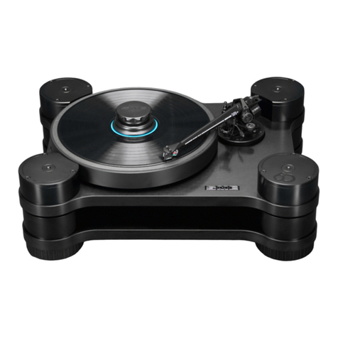
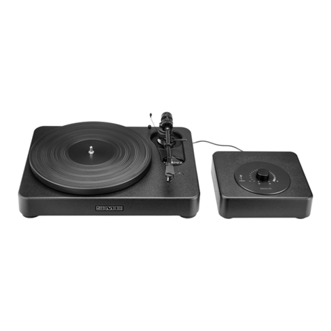
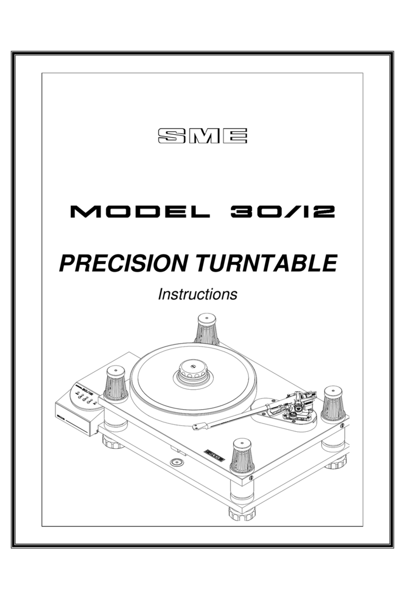
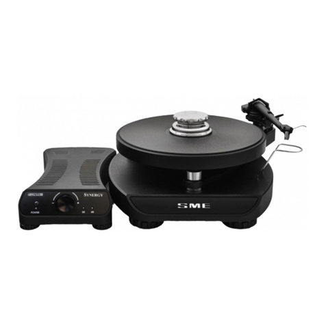
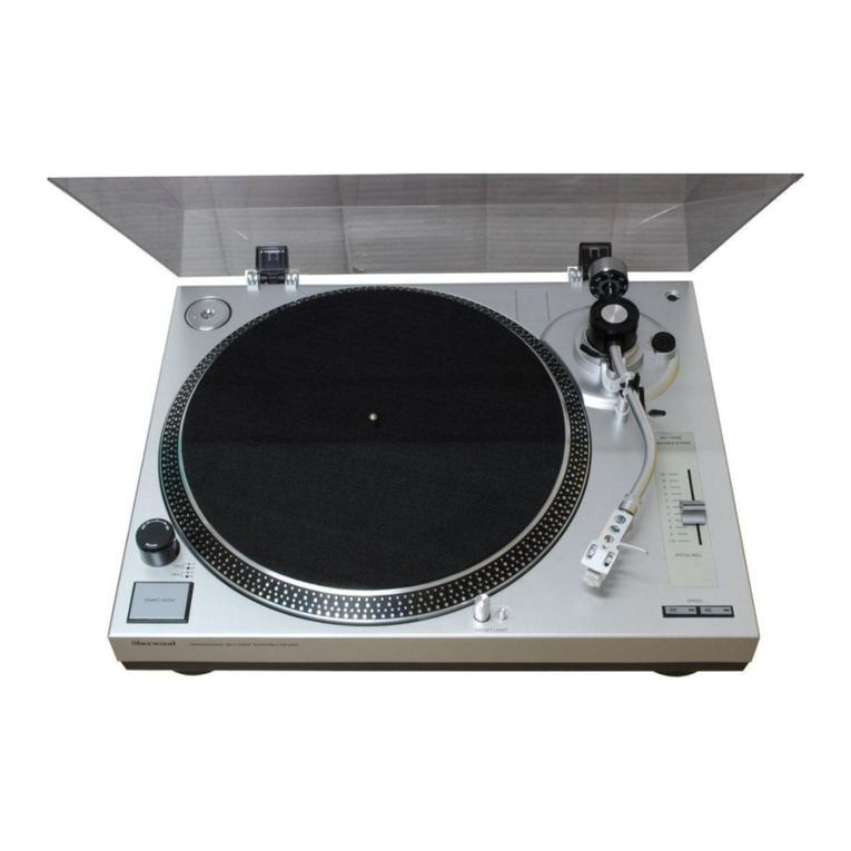
SME Model 6 User manual

INTEGRATED PRECISION TURNTABLE
OWNERS MANUAL
CLASSIC

Instructions
This is no ordinary turntable.
These instrucons include unpacking, set up procedures and specicaons.
Please read carefully.
INTEGRATED PRECISION TURNTABLE
CLASSIC

Warning! Important Safety Instrucons
CAUTION: RISK OF ELECTRIC SHOCK DO NOT REMOVE POWER UNIT COVER.
CAUTION: TO REDUCE THE RISK OF ELECTRIC SHOCK, DO NOT REMOVE THE SPEED CONTROL UNIT (POWER UNIT)
COVER. THERE ARE NO USER SERVICEABLE PARTS INSIDE. REFER ALL SERVICING TO QUALIFIED PERSONNEL.
• Please read this manual carefully and keep it in a safe place for future reference.
• The vent slots in the underside of the Speed Control Unit are for necessary venlaon. To ensure reliable operaon of this apparatus
and to protect from overheang these vents must never be blocked or covered.
• Do not place a water containing vessel on this apparatus, as this can result in a risk of re or electric shock. Do not expose this apparatus
to rain or place it near water.
• If this apparatus accidentally gets wet, unplug it and contact an authorised dealer immediately.
• You can clean this apparatus with a damp cloth when necessary, but be sure to unplug the apparatus rst. To cut o the power source,
unplug the apparatus from the AC wall outlet.
• Do not overload AC wall outlets, power cables or adaptors beyond their capacity as this can result in re or electric shock.
• Power cables should be routed so that they are not likely to be walked on or pinched by items placed upon or against them, paying
parcular aenon to cables at the plug end, adaptors and the point they exit from the appliance.
• Before connecng the AC power cable to the Speed Control Unit, make sure the voltage of the Power Unit, as marked on the idencaon
label at the rear, corresponds to the local electricity supply.
• Never insert anything metallic into the open parts of this apparatus.
• Only a qualied technician should remove the Speed Control Unit cover.
• Be sure to hold the plug, not the power cable, when disconnecng this apparatus from an electric socket.
• Locate this apparatus near an easily accessible AC outlet.
• If this apparatus does not operate normally, in parcular if there are any unusual sounds or smells, unplug it immediately and consult
an authorised dealer.
• Unplug this apparatus from the AC outlet before any service.
1

IMPORTANT NOTICE:
The power cable on this equipment when supplied for use in the UK, is ed with a moulded plug incorporang a fuse. The value of the
fuse is indicated on the pin face of the plug and if it required replacing a fuse approved to BSI 1362 of the same rang must be used. Never
use the plug with the fuse cover omied if the cover is detachable. If the plug ed is not suitable for the power points in your room or if
the power cable is not long enough to reach the power point, you should obtain a suitable safety approved extension lead or consult your
dealer for assistance.
IMPORTANT:
The wires in the power cable are coloured in accordance with the following code: BLUE NEUTRAL, BROWN LIVE. As these colours may not
correspond to the coloured markings idenfying the terminals in your plug, proceed as follows: The wire coloured BLUE must be connected
to the terminal marked with the leer N or coloured BLUE or BLACK. The wire coloured BROWN must be connected to the terminal marked
with the leer L or coloured BROWN or RED.
WARNING:
DO NOT CONNECT EITHER WIRE TO THE EARTH TERMINAL, WHICH IS MARKED WITH THE LETTER (E) OR BY THE EARTH SYMBOL OR
COLOURED GREEN OR GREEN/YELLOW.
WEEE SYMBOL INFORMATION
Correct Disposal of This Product (Waste Electrical & Electronic Equipment)
(Applicable to the European Union and other European countries with separate collecon system).
The marking shown on this product or its literature, indicates that it should not be disposed with other household wastes at the
end of its working life. To prevent possible damage to the environment or human health from uncontrolled waste disposal, please
separate this from other types of wastes and recycle it responsibly to promote the sustainable re-use of material resources.
Household users should contact either the retailer where they purchased this product or their local government oce,
for more detailed informaon of where and how they can take this item for environmentally safe recycling.
Business users should contact their supplier and check the terms and condions of the purchase contract.
This product should not be mixed with other commercial wastes for disposal.
2

Introducon
SME is an iconic brand founded in 1946 by audio legend Alastair Robertson-Aikman in
West Sussex, England. Today SME is recognised as makers of the nest precision turntables
and tonearms in the world. Enrely made in-house by state of the art manufacturing
processes, complemented by tradional crasmanship methods. SME audio has evolved
from 75 years of engineering excellence, innovaon and perfecon delivering precise and
pure audio reproducon.
The Model 6 Classic is a precision turntable with a CNC machined chassis made from
a unique polymer high density resin material which provides high mass and superb
resonance absorpon. The chassis is complemented by a specialist isolaon system
incorporated into the self-levelling feet. The main bearing, spindle and drive pulleys
are precision made to the same exact standards as all SME high-end turntables. Speed
control is a highly sophiscated bi phase, frequency and amplitude, DSP based sine wave
generator, with a dedicated discrete power amplier to drive the motor. It generates
two pure sine waves which drive twin coils present inside a custom made AC motor. The
frequency (speed) is user adjustable in approximately 0.0133 Hz steps allowing a very
accurate musical pitch to be set.
The Model 6 Classic is equipped with the highly credible SME M2-9R tonearm which is
of meculous build quality. Primary features include lightweight stainless steel tonearm
tube, detachable aluminium headshell with double draw pins for extra rigidity and azimuth
adjustment, thumbwheel vercal tracking adjustment, tungsten balance weight(s) and
high quality ball race bearings in all planes. The M2-9R tonearm is designed to suit a wide
range of cartridges up to 38 grams and with a direct plug-in head up to 46 grams.
Design and engineering excellence built by audio enthusiasts for audio enthusiasts.
3

Contents
1 Weights & Dimensions
2 Packing List
3 Parts Idencaon
4 Unpacking
5 Seng Up
6 Operaon – Speed Control
7 Operaon – Turntable
8 Tonearm
9 Maintenance
10 Guarantee
4

1. Weights & Dimensions (mm)
Turntable
Width: 420
Depth: 320
Height: 128
Plaer Diameter: 300
Spindle to Arm: 215.4
Net Weight: 9.1kg
Speed Control Unit
Width: 220
Depth: 200
Height: 85
Net Weight: 2.05kg
Power Consumpon: Idle 5W - Max 10W
5

2. Packing List
Qty Descripon 3
1 Model 6 Serial No □
1 M2-9R Tonearm □
1 Control Unit – 100V □ 115V □ 230V □ □
1 Power Cable – UK □ EU □ USA □ □
1 Plaer □
1 Stroboscopic Disc □
1 Record Clamp □
1 Spindle Washer □
1 Drive Belt □
1 Velcro Strap □
1 Balance Weight □
1 Accessory Weight □
1 Detachable Headshell □
1 Cartridge Screw Set □
1 Bias Weight □
1 Bias Guide □
1 2mm Hex Wrench □
1 0.89mm Hex Wrench □
1 Alignment Protractor □
1 Owner’s Manual □
6

2
5
6
11
10
9
12
7
1
3
4
1. Speed Control Unit
2. Power ON/OFF Buon
3. Rotary Speed Control
4. Plaer
5. Bias Weight
6. Bias Guide
7. An-Skate Lever
8. Balance Weight
9. Tonearm
10. Finger Li
11. Headshell
12. Wayrod/Rider Weight
3. Parts Idencaon
7
8

8
Power Cable & Phono Connectors
Idencaon
Low Voltage
Power Cable 24V
Phono Output
Sockets
Power
ON / OFF
Earth Point
AC Power
Cable Socket
Low Voltage Input
Socket 24V

9
5. Seng Up
1. With the turntable sited, follow the set
up instrucons in the order detailed.
2. Drive belt installaon: place the belt
over the driven pulley, pressing it down
as far as the lower ange and ensuring
free from twists and stretch the belt
over the motor pulley. Rotate the
driven pulley slowly by hand to posion
the belt on the pulleys.
3. Plaer tment: ensure the upper face
of the driven pulley and the underside
of the plaer mang surfaces are
clean, place the plaer squarely over
the turntable spindle lowering it gently
unl it rests on the driven pulley.
4. Speed control unit: t the mains power
cable (check carefully that this matches
your mains power voltage). The mains
voltage seng is indicated on the back
panel.
4. Unpacking
1. Unpack and check all items against the
packing list in Secon 2. In the very
unlikely event that anything is missing
your dealer should be noed at once.
2. The design of the turntable allows it
to be used on any substanal table or
similar piece of furniture in the absence
of a dedicated audio equipment stand.
WARNING! To meet internaonal
safety standards the control unit is
earthed through the yellow/green
wire of the power cable and parcular
care must be taken to ensure that
this is connected in order to maintain
eecve earthing.
5. Low voltage connecon cable: connect
the speed control unit to the turntable
by inserng the cable plug into the
24v input socket at the rear of the
turntable.

6. Timeout: if in adjustment mode and
no adjustments have been made for 20
seconds the new sengs will be saved
and the system will exit adjust mode
and resume running normally.
7. Cancel/Abort Adjustment: with the
motor running and the system in
adjustment mode, if the power buon
is pressed, the motor will stop and any
adjustments that have been made will
be discarded and not saved.
7. Operaon – Turntable
1. Turn on mains power at rear of the speed
control unit (push ON/OFF switch).
2. Place record spindle washer on spindle
followed by the record.
3. Fit record clamp by holding main body
of the clamp and turn locking knob
gently about 1⁄4 turn.
4. Select required speed by pressing the
rotary control buon on speed control
unit unl 33 or 45 is indicated.
5. Press power buon.
6. You are now ready to play your record.
10
appear staonary when the speed is
correct. Whilst forward and reverse
band movement will indicate fast or
slow running respecvely. This is best
observed with the cartridge ed and
the tonearm in the raised posion and
placed directly over the band being
viewed as a reference point.
4. Speed Adjustment: with the motor
running press and hold the rotary buon
for two seconds, the speed indicator
LED will begin to ash. The motor is now
in speed adjust mode and the speed
can now be adjusted in conjuncon
with the stroboscopic disc. Turning the
rotary buon an-clockwise will reduce
speed and clockwise will increase
speed. The method provides a microne
incremental adjustment. When the
speed adjustment is completed depress
and release the rotary buon, the speed
indicator LED light will stop ashing and
become constant and the speed seng
will be stored in the system memory for
future use.
5. Repeat this process for the 45rpm speed
range if required.
The Model 6 precision turntable is
extensively run-in and it’s speeds set before
leaving the factory. If you should wish to
check the speed sengs and make your own
adjustments, the procedure is as follows:
1. Mains Power: the power ON/OFF
buon is located on the rear of the
speed control (power unit). With power
ON the last used speed indicator LED
light will illuminate on the speed control
unit fascia.
2. Motor Power: pressing the power
buon on the speed control unit fascia
will start the motor. With power OFF and
pressing the rotary buon on the fascia
the speed sengs of 33 and 45rpm will
cycle and be indicated by the speed LED.
With the motor running, pressing the
power buon will stop the motor.
3. Speed Tesng: the stroboscopic disc
installed on the plaer is used to check
speeds of 33 and 45rpm. Use the strobe
bands appropriate for your mains AC
frequency. The disc should be viewed
in a uorescent or neon light. The
appropriate band will synchronise and
6. Operaon – Speed Control

11
Note:
Tonearm images for references only, mounng base plate prole may vary.
For your convenience the headshell is supplied detached from the tonearm ready for tment of your cartridge.
Cartridge not supplied – images of cartridge used for illustraon purposes only.
8. Tonearm
• General Arrangements
• Dimensions
• Specicaons
• Fing Balance & Bias Weights
• Fing Headshell & Cartridge
• Tonearm Set Up & Adjustment

12
General Arrangement

13
Dimensions (mm)
A – Pivot to Stylus 233.20
B – Pivot to Turntable Centre 215.40
C – Cartridge Fixing Centres 12.70
D – Oset Angle (degrees) 23.63˚
E – Linear Oset 93.47
F – Overhang 17.80
G – Height above Mounng Surface (Max) 87.00
Height above Mounng Surface (Min) 63.00
H – Mounng Surface to Underside of Headshell (Max) 67.40
Mounng Surface to Underside of Headshell (Min) 43.40
J – Depth below Mounng Surface 46.00
K – Balance Weight Radial Clearance 79.00
Specicaons (g/mm)
Eecve Mass (g) 9.50
Cartridge Balance Range
Headshell: Up to (g) 38.0
Plug-heads: Up to (g) 46.0
Vercal Tracking Force (g) 5.0
Maximum Tracking Error (degree/mm) 0.013
Null Points: Inner (mm radii) 66.04
Outer (mm radii) 120.9
Silver Litz Internal Wiring
RCA Phono – Gold Plated Connectors

14
Anti
-Skate Guide
Accessory Balance Weight
Balance Weight
Anti
-Skate Weight
Anti
-Skate Lever
Arm Lift
M3 Button Head Mounting Screw
& Arm Mounting Washer
Bedplate
Shield Can
Armrest Catch
Armrest
Tonearm
Azimuth Locking Screw
underside tonearm at this point
Arm Socket Nut
Detachable Headshell
Ground Terminal
Control Lever
Base Clamp Nut & Washer
VTA Thumbwheel
Wayrod/Rider Weight
Pillar Clamp Screw
Tonearm Idencaon
Fing Balance & Bias Weights
The tonearm balance and bias weights are packed separately for safety in transit. Carefully screw the balance weight onto the threaded
stud on the rear of the tonearm, the dial should face forward towards the headshell.
Fing of the bias weight is described in the following set up pages.

15
Before ng the cartridge see that the
stylus guard (not illustrated) is in posion
as a precauon against accidental damage.
Cartridge leads may require adjustment for
a snug t. This can be achieved by use of
pointed nose pliers to close connectors or
with a narrow screwdriver blade to splay
(open) connectors. Connecons must
never be made by direct soldering.
The coding is as follows:
Red – Right Channel Signal
Green – Right Channel Ground
White – Le Channel Signal
Blue – Le Channel Ground
Most cartridges have their own screws.
One pair #3-48 UNC x 11mm with nuts
and washers are provided, other lengths
are available from SME.
Examine the top of the cartridge. It is
important that it presents a good at face
to the underside of the headshell. Before
nal ghtening check that the cartridge is
lying parallel to the reference edge of the
headshell, as shown.
Tighten the xing screws securely using a
screwdriver, which must be a good t in
the screw slots to avoid damage. Hold the
nut if necessary to prevent rotaon.
The screws are non-magnec. Damage
can be caused if a screw is snatched by
magnec aracon whilst being oered
up to the cartridge. For the same reason
do not lay down tools nearby.
Fing Headshell & Cartridge

16
WHITE
BLUE
GREEN
RED
WHITE
BLUE
GREEN
RED
WHITE
BLUE
GREEN
RED
Cartridge Lead Replacement
Replacement cartridge leads can be
obtained directly from SME.
They should be ed according to the
colour coding shown looking onto the
headshell from the front.
Fing Headshell
Insert the headshell into the arm socket
and press rmly inwards unl the draw
pins contact the thread of the socket nut.
Maintaining pressure, turn the socket nut
an-clockwise viewed from the front to
draw the headshell home. It should be
ghtened rmly but not to the point of
strain.
Removing Headshell
Removal is the reverse of ng. Holding
the headshell rmly to prevent rotaon
turn the socket nut, clockwise when
viewed from the front, unl the headshell
is completely released.
Take care to avoid damaging the cartridge
during this operaon.

17
Longitudinal Balance
With only the main balance weight ed,
cartridges up to 16g may be balanced.
However by removing the balance weight
end cap and coupling the accessory balance
weight (as illustrated) cartridges up to 38g,
mounted in the headshell or plug in heads
up to 46g can be catered for.
Slide the wayrod/rider weight into the
rearmost zero posion and balance the
tonearm by rotang the balance weight in
the required direcon.
Remove the accessory balance weight,
when needed, by unscrewing an-clockwise
from the balance weight. Replace the
balance weight end cap.
Adjust unl the tonearm (with the cartridge ed) is either level or slightly low at the
front end.
Tonearm Set Up & Adjustment

18
For safety the lever of the lowering control
should now be moved into the raised
posion.
VTF is set aer longitudinal balancing has
been completed.
It is applied by moving the complete
wayrod assembly forward as indicated.
The assembly is calibrated to provide a
maximum of 5.0g VTF in 1.0g increments
between the indent posions.
Posion shown is the seng for 3.0g VTF.
Half gram sengs are indicated by the
shallow grooves alternang with the
indent posions.
Vercal Tracking Force (VTF) Adjustment
Other manuals for Model 6
1
Table of contents
Other SME Turntable manuals
