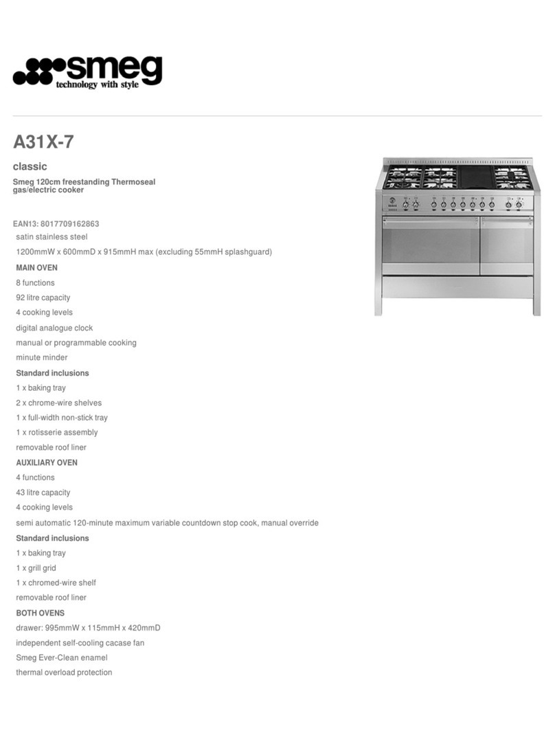
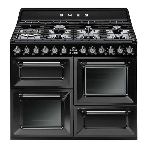
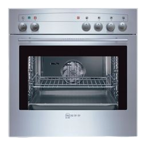
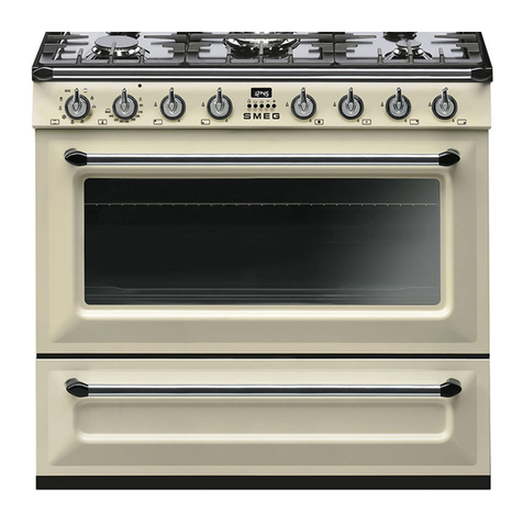
Smeg CS18A/1 User manual

MANUALE D’USO
INSTRUCTION MANUAL
MANUAL DE USO
MANUAL DE INSTRUÇÕES
CUCINA CON
FORNO ELETTRICO
COOKER WITH
ELECTRIC OVEN
COCINA CON
HORNO ELÉCTRICO
FOGÃO COM
FORNO ELÉCTRICO

2
ITALIANO 3–36
Vi ringraziamo per aver scelto questo nostro prodotto.
Vi consigliamo di leggere attentamente questo manuale, che riporta tutte le indicazioni
per mantenere inalterate le qualità estetiche e funzionali della cucina.
ENGLISH 37–69
Thank you for choosing our product.
We advise you to read this manual carefully. It contains all necessary instructions for
maintaining unaltered the appearance and functional qualities of the cooker.
ESPAÑOL 70 – 103
Les agradecemos haber elegido nuestro producto.
Le aconsejamos leer atentamente todas las instrucciones de este manual que ofrece
todas las indicaciones necesarias para mantener inalterables las cualidades estéticas y
funcionales de la cocina.
PORTUGUÊS 104 – 137
Agradecemo-vos por terem escolhido o nosso produto.
Aconselhamos a leitura atenta deste manual que contém todas as indicações para
manter inalteradas as qualidades estéticas e de funcionamento do fogão.

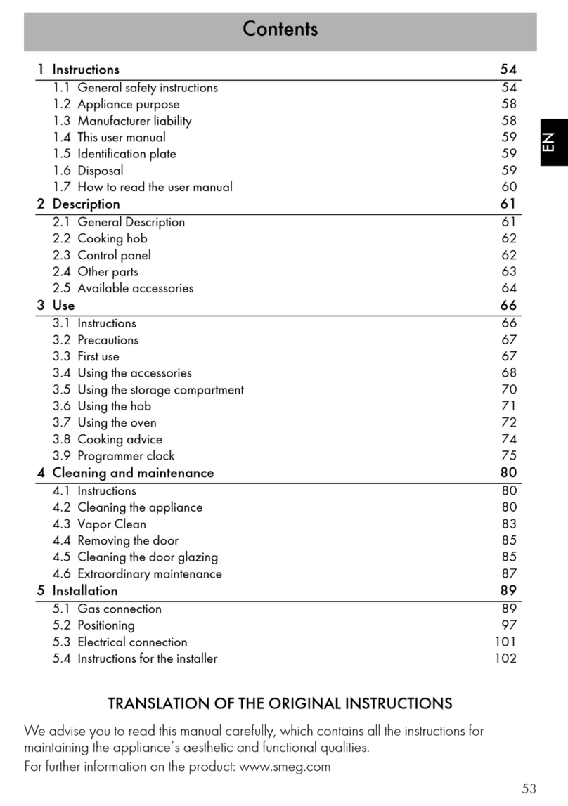
Contents
37
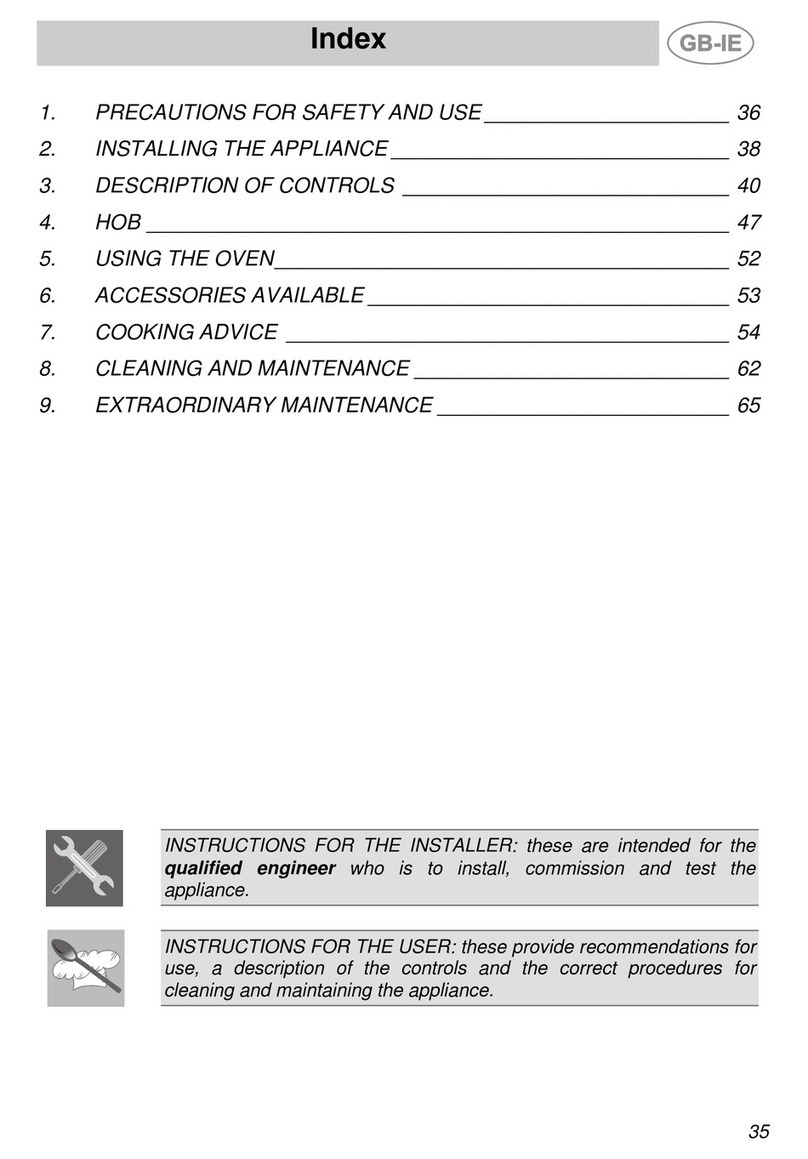
1. INSTRUCTIONS FOR SAFE AND PROPER USE _______________38
2. INSTALLATION OF THE APPLIANCE ________________________40
3. ADAPTATION TO DIFFERENT TYPES OF GAS ________________43
4. FINAL OPERATIONS______________________________________46
5. DESCRIPTION OF CONTROLS _____________________________48
6. USE OF THE COOKING HOB _______________________________55
7. USE OF THE OVEN_______________________________________57
8. AVAILABLE ACCESSORIES ________________________________58
9. COOKING HINTS_________________________________________59
10. CLEANING AND MAINTENANCE ____________________________65
11. EXTRAORDINARY MAINTENANCE __________________________68
THESE INSTRUCTIONS ARE VALID ONLY FOR END USER COUNTRIES WHOSE
IDENTIFICATION SYMBOLS APPEAR ON THE COVER OF THIS MANUAL.
INSTRUCTIONS FOR THE INSTALLER: these are for the qualified
technician who must carry out a suitable check of the gas system,
install the appliance, set it functioning and carry out an inspection test.
INSTRUCTIONS FOR THE USER: these contain user advice,
description of the commands and the correct procedures for cleaning
and maintenance of the appliance.

Introduction
38
1. INSTRUCTIONS FOR SAFE AND PROPER USE
THIS MANUAL IS AN INTEGRAL PART OF THE APPLIANCE AND
THEREFORE MUST BE KEPT IN ITS ENTIRETY AND IN AN ACCESSIBLE
PLACE FOR THE WHOLE WORKING LIFE OF THE COOKER. WE ADVISE
READING THIS MANUAL AND ALL THE INSTRUCTIONS THEREIN BEFORE
USING THE COOKER. ALSO KEEP THE SERIES OF NOZZLES SUPPLIED.
INSTALLATION MUST BE CARRIED OUT BY QUALIFIED PERSONNEL IN
ACCORDANCE WITH THE REGULATIONS IN FORCE. THIS APPLIANCE IS
INTENDED FOR DOMESTIC USES AND CONFORMS TO CURRENT
REGULATIONS IN FORCE. THE APPLIANCE HAS BEEN BUILT TO CARRY
OUT THE FOLLOWING FUNCTIONS: COOKING AND HEATING-UP OF FOOD.
ALL OTHER USES ARE CONSIDERED IMPROPER.
THE MANUFACTURER DECLINES ALL RESPONSIBILITY FOR IMPROPER
USE.
DO NOT LEAVE THE PACKING IN THE HOME ENVIRONMENT. SEPARATE
THE VARIOUS WASTE MATERIALS AND TAKE THEM TO THE NEAREST
SPECIAL GARBAGE COLLECTION CENTRE.
IT IS OBLIGATORY FOR THE ELECTRICAL SYSTEM TO BE GROUNDED
ACCORDING TO THE METHODS REQUIRED BY SAFETY RULES.
THE PLUG TO BE CONNECTED TO THE POWER CABLE AND THE SOCKET
MUST BE THE SAME TYPE AND MUST CONFORM TO CURRENT
REGULATIONS.
THE SOCKET MUST BE ACCESSIBLE AFTER THE APPLIANCE HAS BEEN
BUILT IN.
NEVER UNPLUG BY PULLING ON THE CABLE.
IMMEDIATELY AFTER INSTALLATION CARRY OUT A BRIEF INSPECTION
TEST OF THE APPLIANCE, FOLLOWING THE INSTRUCTIONS BELOW.
SHOULD THE APPLIANCE NOT FUNCTION, DISCONNECT IT FROM THE
SUPPLY AND CALL THE NEAREST TECHNICAL ASSISTANCE CENTRE.
NEVER ATTEMPT TO REPAIR THE APPLIANCE.
ALWAYS CHECK THAT THE CONTROL KNOBS ARE IN THE POSITION
"ZERO" (OFF) WHEN YOU FINISH USING THE HOB.
Introduction
39
NEVER PUT INFLAMMABLE OBJECTS IN THE OVEN: THEY COULD BE
ACCIDENTALLY LIGHTED AND CAUSE FIRES.
DURING USE THE APPLIANCE BECOMES VERY HOT. TAKE CARE NOT TO
TOUCH THE HEATING ELEMENTS INSIDE THE OVEN.
DO NOT INSTALL THIS APPLIANCE ON A RAISED PLATFORM.
THE I.D. PLATE WITH TECHNICAL DATA, REGISTRATION NUMBER AND
BRAND NAME IS POSITIONED VISIBLY IN THE STORAGE COMPARTMENT.
THE PLATE MUST NOT BE REMOVED.
DO NOT PUT PANS WITHOUT PERFECTLY SMOOTH AND FLAT BOTTOMS
ON THE COOKING HOB GRIDS.
NEVER USE THE COOKING HOB AS A WORK SURFACE.
DO NOT USE CONTAINERS OR BROILERS THAT EXTEND BEYOND THE
OUTER PERIMETER OF THE HOB.
THE APPLIANCE IS DESIGNED FOR USE BY ADULTS. DO NOT ALLOW
CHILDREN TO GO NEAR OR PLAY WITH IT.
REPLACED APPLIANCES MUST BE TAKEN TO A SPECIAL GARBAGE
COLLECTION CENTRE.
The manufacturer declines all responsibility for damage to persons
or things caused by non-observance of the above prescriptions or by
interference with any part of the appliance or by the use of non-original
spares.

Instructions for the installer
40
2. INSTALLATION OFTHE APPLIANCE
It is the law that all gas appliances are installed by competent persons.
Corgi gas installers are approved to work to safe and satisfactory
standards. All gas installation, servicing and repair work must be in
accordance with the gas safety regulations 1984 (installation and use) as
amended 1990.
It can be placed against walls higher than the hob, at a distance of at
least 50 mm from the side of the appliance, as shown in the drawings A
and B relating to the installation classes. Wall units or extractor hoods
located above the hob must be at least 750 mm away from it.
AB
SLOT IN FREE STANDING
2.1 Electrical connection
Make sure that the power line voltage matches the specifications
indicated on the rating plate located inside the storage compartment.
This rating plate must never be removed.
The plug at the end of the power cable and the wall socket must be the
same type (conforming to regulations in force). Check that the power line
is adequately grounded. Do not use reducers, adapters or shunts.
On the power line, install an omnipolar cut-off device with contact cut-off
distance greater than or equal to 3 mm, located in an easily accessible
position near the unit.

Instructions for the installer
41
If the power cable is replaced, the wire
section on the new cable must not be
less than 1.5 mm2(3 x 1.5 cable),
keeping in mind that the end to be
connected to the hob must have the
ground wire (yellow-
g
reen) longer by
at least 20 mm. Use only the special
cables available at our Service
Centres.
The manufacturer declines all responsibility for damage to persons
or things caused by non-observance of the above prescriptions or by
interference with any part of the appliance.
2.2 Ventilation requirements
The room containing the appliance should have an air supply in
accordance with B.S. 5440 part 2 1989.
1. All rooms require an opening window or equivalent, and some
rooms will require a permanent vent as well.
2. For room volumes up to 5 m3an air vent of 100 cm2is required.
3. If the room has a door that opens directly to the outside, and the
room exceeds 1 m3no air vent is required.
4. For room volumes between 5 m3and 10 m3an air vent of 50 cm2is
required.
5. If there are other fuel burning appliances in the same room B.S.
5440 part 2 1989 should be consulted to determine the air vent
requirements.
6. This appliance must not be installed in a bed sitting room of less
than 20 m3or in a bathroom or shower room.
Windows and permanent vents should therefore not be blocked or
removed without first consulting a Corgi gas installer.
Failure to install appliances correctly is dangerous and could lead
to prosecution.

Instructions for the installer
42
2.3 Connecting to natural and LPG gas
(Please see connection diagram)
Make the connection to the appliance using flexible
bayonet style hose in accordance to B.S. 669. The
hose connection at the rear of the appliance has a ½”
BSP internal thread. Please use seal Cbetween the
flexible connection Land the appliance supply tube B.
When making the connection, make sure that no stress
of any kind is applied to the cooker and that the hose
does not touch any sharp edges.
If connecting to LPG the bayonet hose must have
red bands on it.

Instructions for the installer
43
3. ADAPTATIONTO DIFFERENTTYPES OF GAS
Before performing any cleaning or maintenance work, detach the
appliance from the electrical socket.
The cooking hob of the cooker is inspection-tested for use with G 20
natural gas at a pressure of 20 mbars. If used with other types of gas,
you have to replace the nozzles and regulate the primary air to the
burners. Then regulate the minimum flame on the gas taps. For nozzle
replacement and burner adjustment you must raise the cooking hob as
described in the following paragraph.
3.1 Raising of cooking hob
Remove the grids, first the middle one then the ones at the sides; remove
all the burner caps, the flame cap crowns and the burners.
1. Remove the programmer buttons;
2. Remove the knobs;
3. Unscrew the front panel fixing screws and remove it after
disconnecting the thermostat tell-tale light faston;
4. Loosen the screws of the hinge on the back of the cooker;
5. Raise the surface from the front end;
6. Place the surface support brackets in the front groove of the side;
7. Proceed to replacement of the burner nozzles in accordance with the
appropriate gas table;
8. Adjust the primary air as described in paragraph “3.2 Regulation for
LPG ”;
9. After adjustment, fully tighten the fixing screws.

Instructions for the installer
44
3.2 Regulation for LPG
Loosen screw Aand push air regulator Bto the bottom.
With a 7 mm wrench, remove nozzle Cand replace it with the proper one
(follow the instructions on the reference tables for the type of gas to be
used). The torque wrench setting of the nozzle must not exceed 3 Nm.
Regulate the air by sliding regulator Buntil reaching distance “X” shown
in the table in paragraph “3.4 Regulation of primary air”. Lock regulator B
by tightening screw A.
Burner
Rated
heating
capacity
(kW)
LPG – G30/G31 28/37 mbar
Nozzle
diameter
1/100 mm
By-pass
mm
1/100
Reduced
flowrate
(W)
Flowrate
g/h G30
Flowrate
g/h G31
Auxiliary 1.05 48 30 380 76 75
Semi rapid 1.65 62 30 380 120 118
Rapid 2.55 76 45 800 185 182
Ultra rapid 3.25 85 65 1400 236 232
Fish pan 1.9 65 48 800 138 136

Instructions for the installer
45
3.3 Regulation for natural gas
The cooking hob has been inspected for G 20 natural gas at a pressure
of 20 mbar. To allow the unit to work with this type of gas, perform the
same operations described in paragraph “3.2 Regulation for LPG ”, but
choose the nozzles and regulate the primary air for natural gas, as shown
in the following table and in paragraph “3.4 Regulation of primary air”.
Burner
Rated
heating
capacity
(kW)
Natural gas – G20 20 mbar
Nozzle diameter
1/100 mm
Reduced flowrate
(W)
Auxiliary 1.05 73 380
Semi rapid 1.65 92 380
Rapid 2.55 115 700
Ultra rapid 3.25 130 1200
Fish pan 1.9 95 750
3.4 Regulation of primary air
Referred to distance “X” in mm.
BURNER
G20
20 mbar
G30/G31
28/37 mbar
Auxiliary 2.5 2.5
Semi rapid 1 1.5
Rapid LH 1.5 2.5
Rapid RH 1.5 2.5
Ultra rapid 1.5 2.5
Fish pan 2.5 3

Instructions for the installer
46
4. FINAL OPERATIONS
Having carried out the above adjustments, reassemble the appliance
following, backwards, the instructions in paragraph “3.1 Raising of
cooking hob”.
After adjustment to a different kind of gas from the one for which the
cooker has been tested, replace the plate inside the storage
compartment with one corresponding to the new kind of gas. This plate
can be obtained from your nearest Authorised Assistance Centre.
4.1 Adjustment of minimum for natural gas
Light the burner and take it to the minimum.
Remove the gas tap knob and turn the
adjustment screw inside or at the side of the tap
shaft (depending on the model) until there is a
regular minimum flame. Replace the knob and
check burner flame stability: (rapidly turning the
knob from maximum to minimum position, the
flame should not go out). Repeat the operation on
all the gas taps.
4.2 Regulation of minimum for LPG
To regulate the minimum for LPG, completely tighten (clockwise) the
screw inside or next to the gas tap pin (depending on the model).
The diameters of the by-passes for each burner are given in table “3.2
Regulation for LPG ”.
4.3 Arrangement of burners on cooking hob
BURNERS
1 Auxiliary
2 Semi rapid
3 Rapid
4 Ultra rapid
5 Fish pan

Instructions for the installer
47
4.4 Positioning and levelling of the appliance
Having carried out the electricity and gas hook-up, level the appliance
using the four adjustable legs.
4.5 Mounting the rear top upstand
• Position the upstand above the top, taking care to align holes Awith
holes B.
• Secure the upstand to the top by tightening screws C.

Instructions for the user
48
5. DESCRIPTION OF CONTROLS
5.1 Front control panel
All the cooker controls and commands are on the front panel.
DESCRIPTION OF SYMBOLS
OVEN THERMOSTAT
REAR RIGHT-HAND
COOKING ZONE
OVEN FUNCTIONS
FRONT RIGHT-HAND
COOKING ZONE
FRONT LEFT-HAND
COOKING ZONE
FISH COOKING ZONE
REAR LEFT-HAND
COOKING ZONE
FRONT CENTRAL
COOKING ZONE
THERMOSTAT KNOB
Selection of cooking temperature is carried out
by turning the knob clockwise to the required
temperature, between 50° and 250°C.
The tell-tale light comes on to indicate that the
oven is warming up.
When it goes out it means that the required temperature has been
reached. Regular flashing means that oven temperature is being
constantly maintained at the programmed level.

Instructions for the user
49
FUNCTION SWITCH KNOB
Turn the knob to select from the following
functions:
NO FUNCTION SET
OVEN LIGHT
GRILL ELEMENT +
VENTILATION
UPPER AND LOWER
HEATING ELEMENT
LOWER HEATING ELEMENT +
VENTILATED HEATING ELEM.
GRILL ELEMENT
VENTILATED HEATING
ELEMENT + VENTILATION
COOKING HOB BURNER
COMMAND KNOB
To light the flame, press and turn the knob
anticlockwise to the large flame symbol. Adjust
the flame by turning the knob to the area
comprised between maximum and minimum
marks. To turn off, set the knob to either "zero".

Instructions for the user
50
5.2 Electronic Programmer
LIST OF FUNCTIONS
MINUTE-COUNTER KEY
COOKING TIME KEY
END-OF-COOKING KEY
DECREASE TIME KEY
INCREASE TIME KEY
5.2.1 Clock adjustment
When using the oven for the first time, or after a power failure, the display
flashes regularly and indicates . Press the keys and at
the same time the keys o : each single press changes the time by 1
minute either up or down.
Before setting the programmer activate the desired function and
temperature.
5.2.2 Semiautomatic cooking
Use this setting for automatic oven switch-off at the end of cooking time.
By pressing key , the display lights up, showing ; keep the key
pressed and at the same time, press keys o to set the cooking
time.

Instructions for the user
51
Release key to start the programmed cooking time count. The display
will now show the right time together with symbols Aand .
5.2.3 Automatic cooking
Use this setting to automatically start and stop the oven.
By pressing key , the display lights up showing ; keep the key
pressed and at the same time, press keys or to set the cooking
time.
By pressing key the sum of the right time + cooking time will appear;
keep the key pressed and at the same time, press keys o to
regulate the end of cooking time.
Release key to start the programmed count and the display will show
the right time together with symbols A and .
After set-up, to see the cooking time remaining, press the key ; to see
the end of cooking time press the key .
Set-up with incoherent values is logically prevented (e.g. the contrast
between a cooking time and a longer period will not be accepted by the
programmer).
5.2.4 End of cooking
When cooking is over, the oven will automatically switch off and, at the
same time, an intermittent alarm will sound. After switching off the alarm,
the display will once again show the right time together with the symbol
, indicating that the oven has returned to manual operation mode.
5.2.5 Adjusting alarm volume
The acoustic alarm has three different settings. These can be operated,
while the alarm is sounding, by pressing key .

Instructions for the user
52
5.2.6 Switching off the alarm
The alarm switches off automatically after seven minutes. They can be
manually de-activated by pressing the keys and together.
5.2.7 Minute Counter
The programmer can also be used as a simple minute counter. By
pressing key , the display shows ; keep the key pressed and
at the same time press keys o . On releasing the key ,
programmed counting will begin and the display will show the current
time and the symbol .
After set-up, to see the remaining time, press the key .
Use as a minute counter does not interrupt functioning of the oven at the
end of the programmed time.
5.2.8 Cancellation of set data
Once the programme has been set, keep the key of the function to be
cancelled pressed, while at the same time is reached by means
of variation keys o . Time cancellation will be considered as end-of-
cooking time by the programmer.
5.2.9 Changing the set data
The cooking data entered can be changed at any time by keeping the
function key pressed and at the same time adjusting the keys o .

Instructions for the user
53
5.3 Analog Programmer
5.3.1 Clock adjustment
To set precise time, PRESS and rotate the inner knob Ain either direction
as required.
Before setting programmer, select desired cooking mode and
temperature.
5.3.2 Semiautomatic cooking
Use this setting for automatic oven switch-off at the end of cooking time
(maximum programmable time: 3hrs and 30 min).
1. Turn the outer knob Bclockwise. This will cause the inner disc to
start moving; set the red pointer Cto the desired end-of-cooking
time.
2. Turn the outer knob Banticlockwise. This will cause the red area D
to widen; set to the current clock time (start of cooking).
Upon expiry of set cooking time, the oven turns off automatically, with “0”
appearing in window Eand an audible signal being given off. To de-
activate, turn the outer knob B clockwise until the symbol appears in
window E.

Instructions for the user
54
5.3.3 Automatic cooking
Use this setting to automatically start and stop the oven (maximum
programmable time: 3hrs and 30 min).
1. Turn the outer knob Bclockwise. This will cause the inner disc to
start moving; set the red pointer Cto the desired end-of-cooking
time.
2. Turn the outer knob B anticlockwise. This will cause the red area D,
corresponding to the duration of cooking, to widen. The point at
which knob Bis released corresponds to start of cooking.
The oven will now come on, heating up to the set temperature, and will
stay on throughout the entire programmed cooking time. Upon expiry of
set time, the oven will automatically turn off with “0” appearing in window
Eand an audible signal being given off. To de-activate, turn the outer
knob Bclockwise until the symbol appears in window E.
5.3.4 Minute counter
The minute counter can be used separately or in conjunction with the
programmer. To set, rotate inner knob Aclockwise until the pointer is
aligned with the desired value (maximum 55 minutes). Upon set time
elapsing, an audible signal will be given off; to de-activate, turn inner
knob Aanticlockwise until pointer is aligned with the symbol.
Note: Setting off of the audible signal does not turn off the oven.
5.3.5 Manual cooking
To operate the oven manually (i.e. without any time limit), rotate outer
knob Buntil the symbol appears in window E.
This manual suits for next models
8
Table of contents
Other Smeg Cooker manuals

Smeg
Smeg Classica SSA91MAX9 User manual

Smeg
Smeg Classica CG90IANT9 User manual

Smeg
Smeg CO61CMP User manual

Smeg
Smeg C6IMXI9 User manual

Smeg
Smeg Victoria TR90IGR User manual

Smeg
Smeg Portofino CPF9IPYW User manual

Smeg
Smeg Portofino CPF92GMBL User manual

Smeg
Smeg Mista Aesthetic B901GMXI9 User manual

Smeg
Smeg Concerto SX91MDS9 User manual

Smeg
Smeg CS19ID-5 User guide