Smeg KEIV90E User manual

KEIV90E
Libretto d’uso
User manual
Manuel d’utilisation
Gebrauchsanleitung
Gebruiksaanwijzing
Manual de uso
Livro para utilização

2
2
INDICE
CONSIGLI E SUGGERIMENTI.............................................................................................................................................. 4
CARATTERISTICHE.............................................................................................................................................................. 5
INSTALLAZIONE................................................................................................................................................................... 7
USO...................................................................................................................................................................................... 11
MANUTENZIONE ................................................................................................................................................................ 12
INDEX
RECOMMENDATIONS AND SUGGESTIONS................................................................................................................... 13
CHARACTERISTICS...........................................................................................................................................................14
INSTALLATION.................................................................................................................................................................... 16
USE...................................................................................................................................................................................... 20
MAINTENANCE...................................................................................................................................................................21
SOMMAIRE
CONSEILS ET SUGGESTIONS.......................................................................................................................................... 22
CARACTERISTIQUES......................................................................................................................................................... 23
INSTALLATION.................................................................................................................................................................... 25
UTILISATION....................................................................................................................................................................... 29
ENTRETIEN......................................................................................................................................................................... 30
INHALTSVERZEICHNIS
EMPFEHLUNGEN UND HINWEISE................................................................................................................................... 31
CHARAKTERISTIKEN.........................................................................................................................................................32
MONTAGE........................................................................................................................................................................... 34
BEDIENUNG........................................................................................................................................................................38
WARTUNG...........................................................................................................................................................................39
INHOUDSOPGAVE
ADVIEZEN EN SUGGESTIES............................................................................................................................................. 40
EIGENSCHAPPEN.............................................................................................................................................................. 41
INSTALLATIE.......................................................................................................................................................................43
GEBRUIK............................................................................................................................................................................. 47
ONDERHOUD...................................................................................................................................................................... 48
INDICE
CONSEJOS Y SUGERENCIAS........................................................................................................................................... 49
CARACTERÍSTICAS ...........................................................................................................................................................50
INSTALACIÓN..................................................................................................................................................................... 52
USO......................................................................................................................................................................................56
MANTENIMIENTO...............................................................................................................................................................57
IT
EN
FR
DE
NL
ES

3
3
ÍNDICE
CONSELHOS E SUGESTÕES............................................................................................................................................ 58
CARACTERÍSTICAS ...........................................................................................................................................................59
INSTALAÇÃO....................................................................................................................................................................... 61
UTILIZAÇÃO........................................................................................................................................................................ 65
MANUTENÇÃO.................................................................................................................................................................... 66
PT

EN 1
13
RECOMMENDATIONS AND SUGGESTIONS
The Instructions for Use apply to several versions of this appliance. Accordingly, you may find
descriptionsofindividualfeaturesthatdonotapplytoyourspecificappliance.
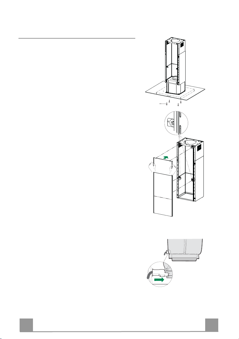
INSTALLATION
• The manufacturer will not be held liable for any damages resulting from incorrect or improper
installation.
• The minimum safety distance between the cooker top and the extractor hood is 650 mm (some
models can be installed at a lower height, please refer to the paragraphs on working dimensions
andinstallation).
• Checkthatthemains voltagecorresponds to that indicatedon the ratingplate fixed to the insideof
thehood.
• ForClassIappliances,checkthatthedomesticpowersupplyguaranteesadequateearthing.
Connecttheextractortotheexhaust fluethrougha pipe of minimumdiameter 120 mm.Theroute
ofthefluemustbeasshortaspossible.
• Donotconnecttheextractorhoodtoexhaustductscarryingcombustionfumes(boilers, fireplaces,
etc.).
• Iftheextractorisusedinconjunctionwithnon-electrical appliances(e.g.gasburningappliances),a
sufficient degree of aeration must be guaranteed in the room in order to prevent the backflow of
exhaust gas. Thekitchen musthave anopening communicating directlywith theopen air inorder
to guarantee the entry of clean air. When the cooker hood is used in conjunction with appliances
supplied with energy other than electric, the negative pressure in the room must not exceed 0,04
mbartopreventfumesbeingdrawnbackintotheroombythe cookerhood.
• In the event of damage to the power cable, it must be replaced by the manufacturer or by the
technicalservicedepartment,inorderto preventanyrisks.
• Iftheinstructionsforinstallationforthegashob specifyagreaterdistance specifiedabove,thishas
tobetakenintoaccount.Regulationsconcerningthedischargeofairhavetobefulfilled.
USE
• Theextractorhoodhasbeendesignedexclusivelyfordomesticusetoeliminatekitchensmells.
• Neverusethehoodforpurposesotherthanforwhichithasbeendesigned.
• Neverleavehighnakedflamesunderthehoodwhenitisinoperation.
• Adjust the flame intensity to direct it onto the bottom of the pan only, making sure that it does not
engulfthesides.
• Deepfatfryersmustbecontinuouslymonitoredduringuse:overheatedoilcanburstintoflames.
• Donotflambèundertherangehood;riskoffire
• This appliance is not intended for use by persons (including children) with reduced physical, sen-
soryormentalcapabilities,orlackofexperience andknowledge,unlesstheyhavebeen givensu-
pervisionorinstructionconcerninguseofthe appliancebyapersonresponsiblefortheirsafety.
• Childrenshouldbesupervisedtoensurethattheydonotplaywiththeappliance.
• “CAUTION:Accessiblepartsmaybecomehotwhenusedwithcookingappliances.”.
MAINTENANCE
• Switch off or unplug the appliance from the mains supply before carrying out any maintenance
work.
• Cleanand/orreplacetheFilters afterthespecifiedtimeperiod(Firehazard).
• Cleanthehoodusingadampclothandaneutralliquiddetergent.
The symbol on the product or on its packaging indicates that this product may not be treated as household waste. Instead it shall be handed over to the
applicablecollectionpointfortherecyclingofelectricalandelectronicequipment.Byensuringthisproductisdisposedofcorrectly,youwillhelppreventpotentialnegative
consequencesfortheenvironmentandhumanhealth,whichcouldotherwisebecausedbyinappropriatewastehandlingofthisproduct.Formoredetailedinformation
aboutrecyclingofthisproduct,pleasecontactyourlocalcityoffice,yourhouseholdwastedisposalserviceortheshopwhereyoupurchasedtheproduct.
2°

EN 1
14
CHARACTERISTICS
Components
Ref. Q.ty Product Components
1 1 Hood Canopy complete with: Controls, Light, Filters
21 Telescopic chimney, made up of:
2.1 1 Upper chimney
2.2 1 Lower chimney
31 Telescopic panel, made up of:
3.1 1 Upper panel
3.2 1 Lower panel
91 Reduction flange ø 150-120 mm
14.1 1 Air Outlet Connector Extension
15 1 Air Outlet Connector
16 1 Novastick tape
25 Hose clamps (not supplied)
Ref. Q.ty Installation Components
7.3 1Air outlet connector fixing bracket
7.2 1Telescopic chimney fixing bracket
11 4 Wall plugs ø 10
12c 2 Screws 2.9 x 6.5
12e 2 Screws 2.9 x 9.5
12f 4 Screws M4 x 80
12g 4 Screws M6 x 80
12h 4 Screws 5.2 x 70
21 1 Drilling template
22 4 Washers ø 6.4
23 4 Nuts M6
Q.ty Documentation
1Instruction Manual
12h
11
12g
22
23
21
25
12f
7.2
12c
12e
9
3
3.1
3.2
2
2.1
2.2
1
1
14.1 15
7.3
16

EN 1
15
Dimensions
Min.
500mm
Min.
650mm

EN 1
16
INSTALLATION
Drilling the Ceiling/shelf and fixing the frame
DRILLING THE CEILING/SHELF
• Use a plumb line to mark the centre of the hob on the ceiling/support shelf.
• Place the drilling template 21 provided on the ceiling/support shelf, making sure that the
template is in the correct position by lining up the axes of the template with those of the hob.
• Mark the centres of the holes in the template.
• Drill the holes at the points marked:
• For concrete ceilings, drill for plugs appropriate to the screw size.
• For hollow brick ceilings with wall thickness of 20 mm: drill ø 10 mm(immediately insert
the Dowels 11 supplied).
• For wooden beam ceilings, drill according to the wood screws used.
• For wooden shelf, drill ø 7 mm.
• For the power supply cable feed, drill ø 10 mm.
• For the air outlet (Ducted Version), drill according to the diameter of the external air ex-
haust duct connection.
• Insert two screws of the following type, crossing them and leaving 4-5 mm from the ceiling:
• For concrete ceilings, use the appropriate plugs for the screw size (not provided).
• for Cavity ceiling with inner space, with wall thickness of approx. 20 mm, Screws 12h,
supplied.
• For wooden beam ceilings, use 4 wood screws (not provided).
• For wooden shelf, use 4 screws 12g with washers 22 and nuts 23, provided.

EN 1
17
Fixing the Frame/Chimney
Should it be necessary to adjust the height of the frame, proceed
as follows:
• Unfasten the metric screws joining the two opposite parts that
can be seen from the front;
• Adjust the height of the frame as required, then replace the
screws removed as above, making sure that you insert 2 of
them close to the panel lock;
• Lift the frame, insert the slots onto the screws and slide them
until they lock;
• Tighten the two screws and insert the other two screws pro-
vided.
• Take the telescopic chimney locking bracket 7.2, remove the
film from the double sided adhesive and fix it inside the frame
so as to hold it more firmly.
Before final locking of the screws it is possible to make small
adjustments to the frame, making sure that the screws do not
come out of the adjustment slot.
• The Frame must be securely fastened both due to the weight of
the Hood and the stress caused by occasional sideways pres-
sure on the Appliance when in position. When fastened, check
that the base is stable even when the Frame is subjected to
bending.
• In all cases where the Ceiling is not sufficiently strong at the
point of suspension, the Installation technician must strengthen
it with suitable plates and counterplates, anchored to structur-
ally sound elements.
2
1
2
1
Ducted version air exhaust system Connection
When installing the ducted version, connect the hood to the
chimney using either a flexible or rigid pipe ø 150 or 120 mm,
the choice of which is left to the installer.
• To install a ø 120 mm air exhaust connection, insert the re-
ducer flange 9on the hood body outlet.
• Fix the pipe using the pipe clamps 25 (not provided).
• Remove any activated charcoal filters.
ø 150
9
ø 120

EN 1
18
Air outlet – Recirculation Version
• Insert the Connector extensions 14.1 into the side of the Con-
nector 15.
• Insert the Connector 15 into the Support bracket 7.3 and fix it
with the screws.
• Fasten the Support bracket 7.3, fixing it to the upper part with
the Screws.
• Make sure that the Connector extensions outlet 14.1 is in cor-
respondence with the Chimney openings both horizontally and
vertically.
• Join the Connector 15 to the Hood canopy outlet using a rigid
or flexible pipe ø¸150 mm, selection of which is at the discre-
tion of the installation technician.
• Make sure that the Activated charcoal odour filter has been
fitted.
7.3
7.3
12c
12e
15
14.1
Application of Novastick Tape
• Apply the Novastick tape 16 to the front edge of the Upper
Chimney from the top part down to the start of the Lower
Chimney.

EN 1
19
Fitting the Panel and Fixing the Hood Canopy
Before fixing the Hood Canopy to the Frame:
• Remove the Grease filters from the Hood Canopy;
• Remove any Activated charcoal filters.
• Working from below, fix the Hood canopy to the
Frame provided, using the 4 screws 12f (M6 x 10)
provided.
• Then hook the upper part of the Panel 3, adjusted to
size, to the rubber supports in the upper part and in
the lower part of the Frame.
• Slide the lower part of the Panel 3until its metal tabs
slot into the slots in the frame;
12f
ELECTRICAL CONNECTION
• Connect the hood to the mains through a two-pole
switch having a contact gap of at least 3 mm.
• Remove the grease filters (see paragraph Mainte-
nance) being sure that the connector of the feeding
cable is correctly inserted in the socket placed on the
side of the fan.

EN 2
20
USE
T2
T1 L
T3
Control panel
BUTTON LED FUNCTIONS
T1 Speed On Turns the Motor on at Speed one.
Turns the Motor off.
T2 Speed On Turns the Motor on at Speed two.
T3 Speed Fixed When pressed briefly, turns the Motor on at Speed three.
Flashing Pressed for 2 Seconds.
Activates Speed four with a timer set to 6 minutes, after which
it returns to the speed that was set previously. Suitable to deal
with maximum levels of cooking fumes.
LLight Turns the Lighting System on and off.
Warning: Button T1 turns the motor off, after first passing to speed one.

EN 2
21
MAINTENANCE
Grease filters
CLEANING METAL SELF- SUPPORTING GREASE FILTERS
• The filters must be cleaned every 2 months of operation, or
more frequently for particularly heavy usage, and can be
washed in a dishwasher.
• Remove the filters one at a time by pushing them towards the
back of the group and pulling down at the same time.
• Wash the filters, taking care not to bend them. Allow them to
dry before refitting.
• When refitting the filters, make sure that the handle is visible
on the outside.
Activated charcoal filter (Recirculation version)
REPLACING THE ACTIVATED CHARCOAL FILTER
• The filter is not washable and cannot be regenerated, and must
be replaced approximately every 4 months of operation, or
more frequently for particularly heavy usage.
• Remove the metal grease filters.
• Remove the saturated activated carbon filter by releasing the
fixing hooks.
• Fit the new filter by hooking it into its seating.
• Refit the metal grease filters.
Lighting unit
Warning: This appliance is fitted with a white LED lamp classed
as 1M according to EN 60825-1: 1994 + A1:2002 + A2:2001
standards; maximum optical power emitted @439nm: 7µW. Do
not look directly at the light through optical devices (binoculars,
magnifying glasses…).
• For replacement contact technical support. ("To purchase con-
tact technical support")
Table of contents
Other Smeg Ventilation Hood manuals