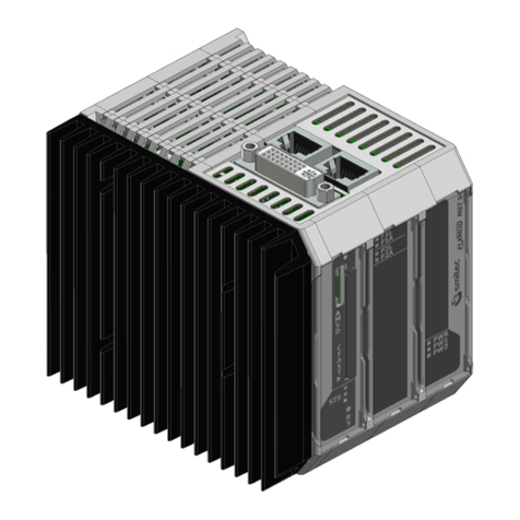
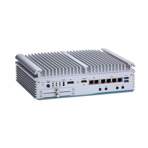
Smitec FLXMOD CPC 04 Series User manual

FLXMOD CPC 04XX series Installation, use and maintenance manual - EN
Ver. 1.02 1
Smitec S.p.A., viale Vittorio Veneto 4, 24016 San Pellegrino Terme (BG), Italy, www.smitec.it
Installation, use and maintenance manual
INDUSTRIAL PCs
FLXMOD CPC 04XX SERIES
BEFORE STARTING UP THE INDUSTRIAL PC OF FLXMOD CPC 04XX SERIES, CARE-
FULLY READ THIS MANUAL AND FOLLOW ALL INSTRUCTIONS, IN ORDER TO EN-
SURE MAXIMUM SAFETY
The technical data and the drawings in this manual might have been modified later; always
refer to the latest version.

FLXMOD CPC 04XX series Installation, use and maintenance manual - EN
Ver. 1.02 2
Summary
1 Preface ....................................................................................................................................................... 4
2 General warnings ...................................................................................................................................... 5
3 Safety instructions .................................................................................................................................... 7
3.1 General information ............................................................................................................................ 7
3.2 Precautions during handling and assembly ........................................................................................ 7
4 Product description .................................................................................................................................. 8
4.1 Pictures of module CPC 04XX ............................................................................................................ 9
5 Technical data ......................................................................................................................................... 10
5.1 Environmental specifications ............................................................................................................ 10
5.2 Electrical specifications ..................................................................................................................... 10
5.3 Mechanical specifications ................................................................................................................. 11
5.3.1 Mechanical dimensions ............................................................................................................. 11
5.3.1.1 Front view ......................................................................................................................... 11
5.3.1.2 Rear view .......................................................................................................................... 12
5.3.1.3 Top view ........................................................................................................................... 13
5.3.1.4 Bottom view ...................................................................................................................... 14
5.4 Hardware features ............................................................................................................................ 15
5.4.1 Basic hardware ......................................................................................................................... 15
5.4.1.1 CPC 0401 ......................................................................................................................... 15
5.4.1.2 CPC 0402 ......................................................................................................................... 16
5.5 Order codes ...................................................................................................................................... 16
5.6 Accessories ....................................................................................................................................... 16
6 Connections and LEDs ........................................................................................................................... 17
6.1 Front view ......................................................................................................................................... 17
6.1.1 Connection references .............................................................................................................. 17
6.1.2 Signalling LEDs ......................................................................................................................... 18
6.2 Top view ............................................................................................................................................ 18
6.2.1 Connection references .............................................................................................................. 18
6.3 Bottom view ..................................................................................................................................... 19
6.3.1 Model CPC 0401 ....................................................................................................................... 19
6.3.2 Connection references .............................................................................................................. 19
6.3.3 Model CPC 0402 ....................................................................................................................... 20
6.3.3.1 Connection references ...................................................................................................... 20
6.3.4 24V IN power supply ................................................................................................................. 21
6.4 USB port ........................................................................................................................................... 22
6.5 Ethernet port ..................................................................................................................................... 22
6.5.1 Model CPC 0401 ....................................................................................................................... 22
6.5.2 Model CPC 0402 ....................................................................................................................... 23
6.5.2.1 Model CPC 0401 .............................................................................................................. 23
6.5.2.1.1 LED behavior of communication speed signaling ..................................................... 23
6.5.2.1.2 LED behavior for signaling connection and communication activities ...................... 23
6.5.2.2 Model CPC 0402 .............................................................................................................. 24
6.5.2.2.1 LED behavior of communication speed signaling ..................................................... 24
6.5.2.2.2 LED behavior for signaling connection and communication activities ...................... 24
6.6 RS485 port ........................................................................................................................................ 25
6.7 Housing socket of CFast card memory and micro SD (MSD) memory ............................................. 26
6.8 Reset button ...................................................................................................................................... 26
7 Installation ............................................................................................................................................... 27
7.1 Assembly .......................................................................................................................................... 27
7.2 Environmental requirements ............................................................................................................. 28
7.3 Electrical wiring ................................................................................................................................. 28
8 Use ........................................................................................................................................................... 29

FLXMOD CPC 04XX series Installation, use and maintenance manual - EN
Ver. 1.02 3
8.1 CFast card ........................................................................................................................................ 29
8.2 Micro SD card ................................................................................................................................... 29
8.3 Priority of the start-up devices .......................................................................................................... 30
9 Ordinary maintenance ............................................................................................................................ 31
9.1 Clock battery replacement ................................................................................................................ 31
10 Appendices ............................................................................................................................................ 34
10.1 Appendix I: CMOS Setup parameters ............................................................................................. 34
11 Analytical index ..................................................................................................................................... 35

FLXMOD CPC 04XX series Installation, use and maintenance manual - EN
Ver. 1.02 4
1 Preface
This manual provides all necessary information for the installation, use and maintenance of FLXMOD CPC
04XX modules.
The instructions included in this manual are addressed to the following professionals:
The present instructions must be made available to all the above individuals.
User User is a person, a company or an institution that buys the equipment and
uses it for the purposes it was designed for.
User/operator User or operator is a person authorized by the user to operate on the equip-
ment.
Specialized personnel It refers to all persons with specific competence, able to recognize and avoid
the dangers deriving from the use of the equipment.

FLXMOD CPC 04XX series Installation, use and maintenance manual - EN
Ver. 1.02 5
2 General warnings
These assembly instructions are an integral part of the equipment, and must be kept for future reference until
decommissioning.
The user should be informed that the present instructions reflect the state of the art at the moment when the
equipment was sold; they will remain fully acceptable despite subsequent upgrades based on new experienc-
es.
In order to make the manual consultation easier, the following symbols have been adopted:
DO NOT USE THE EQUIPMENT, NOR MAKE ANY INTERVENTION BEFORE INTE-
GRALLY READING AND UNDERSTANDING THIS MANUAL.
IN PARTICULAR, ADOPT ALL SAFETY PRECAUTIONS AND PRESCRIPTIONS INDICATED IN THIS
MANUAL.
THE EQUIPMENT CANNOT BE USED FOR PURPOSES DIFFERENT THAN THE ONES DESCRIBED IN
THIS MANUAL; SMITEC S.p.A. SHALL NOT BE HELD RESPONSIBLE FOR ANY DAMAGES, INCON-
VENIENCES OR ACCIDENTS DUE TO THE NON-COMPLIANCE WITH THESE PRESCRIPTIONS.
Indication of “PROHIBITED ACTION”.
The symbol "DANGER" is used when the non-respect of the prescriptions or the tampering
of organs can cause serious harm to people or things.
The symbol “USE OF INDIVIDUAL PROTECTIONS” means that protective gloves must be
worn.
Indication of “INFORMATION OF PARTICULAR RELEVANCE”.

FLXMOD CPC 04XX series Installation, use and maintenance manual - EN
Ver. 1.02 6
The safety prescriptions aim at establishing a series of behaviors and obligations to be complied with, while
performing the activities described later on in this manual.
These prescriptions constitute the prescribed method of operating the device, in a way that is safe for person-
nel, equipments and environment.

FLXMOD CPC 04XX series Installation, use and maintenance manual - EN
Ver. 1.02 7
3 Safety instructions
3.1 General information
3.2 Precautions during handling and assembly
Do not install or use the equipment before integrally reading and understanding this manual.
In case of difficulties of interpretation, contact SMITEC technical service.
It is absolutely forbidden to use the equipment for different purposes than the ones de-
scribed in this manual. The technical data and the drawings in this manual might have been
modified later; always refer to the latest version. All upgrades can be requested to SMITEC
S.p.A. directly.
Make sure that the personnel is qualified and adequately informed about the risks he may
run and how to avoid them.
FLXMOD CPC 04XX industrial PCs can be used only after the classification of the machine
operating area and after checking the safety levels, which must correspond to the assembly
safety levels.
Use adequate tools during the assembly, in order to avoid crushing or abrasions.
Metal components and sharp surfaces may cause cuts and tears. In case of contact, be very
careful and wear the personal protection equipment.

FLXMOD CPC 04XX series Installation, use and maintenance manual - EN
Ver. 1.02 8
4 Product description
The CPC 04XX module is an industrial PC based on Intel® 64 architecture. Housed in a very compact plastic
housing, it has been designed for standard DIN rail mounting and designed to integrate seamlessly into a FLX-
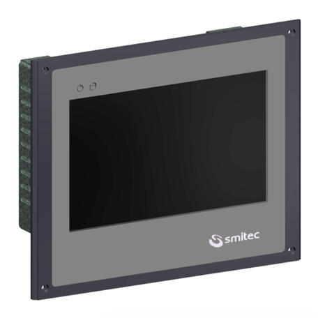
MOD automation system. Depending on the model, the CPC module can be combined with a HMI B1 touch
display (model CPC 0401) or connected to an external monitor via a DVI-D output on a DVI-I connector (model
CPC 0402). In both models, the CPC module is a complete system for man-machine interfacing.
The computing capacity of the CPX 04XX device is given by the Intel® Atom ™ Quad Core processor x5-E8000
(1.04GHz) with 2GB 1600MT / s DDR3L RAM memory.
To meet the most different interfacing needs, the CPC module provides the possibility to connect also standard
input / output devices, such as keyboard, mouse, USB hub, via the integrated USB 3.0 port and a proprietary
display-touchscreen interface panel for via an HMI output or via a DVI-D output (in both cases on a DVI-I con-
nector to ensure compatibility).
The CPC module can communicate with the outside world via a USB 3.0 port, 1 Ethernet 10/100 / 1000Mb port
and an RS485 serial port for the CPC 0401 model, or via a USB 3.0 port and two 10/100 / 1000Mb Ethernet
ports for the CPC 0402 model.
It also has a socket for connecting a micro-SD memory and a socket for connecting a CFast memory, ideal for
storing the operating system, programs and data as it is a high-speed flash-type solid-state memory with SATA
interface, characterized by exceptional resistance to shocks and vibrations. CFast and micro SD memories are
supplied as an accessory.
The position of the CFast and micro SD memories inside the CPC 04XX module is such that it can be extracted
without opening it.

FLXMOD CPC 04XX series Installation, use and maintenance manual - EN
Ver. 1.02 9
4.1 Pictures of module CPC 04XX

FLXMOD CPC 04XX series Installation, use and maintenance manual - EN
Ver. 1.02 10
5 Technical data
5.1 Environmental specifications
5.2 Electrical specifications
The specifications below refer to the CPC 04XX unit alone, without any peripheral unit connected.
All the technical data in this section correspond to the hardware configuration of the CPC
04XX manufactured on the date when this manual was drawn up. To improve or update this
product, SMITEC S.p.A. reserves the right to modify its technical features without notice.
Operating temperature 0° ÷ +40°C when it is operating
Storage temperature -20° ÷ +85°C when it is not operating
Relative humidity 0 ÷ 95% (without condensation)
Housing Polyamide (PA66) and aluminum
Protection degree IP20 according to IEC 60529
Altitude (operation) Up to 2000 m above sea level (corresponding to an
atmospheric pressure from 80 to 106 kPa)
Altitude (storage and transportation) Up to 3000 m above sea level (corresponding to an
atmospheric pressure from 70 to 106 kPa)
Mains voltage 24 VDC (- 15% ÷ +20% according to IEC 61131-2)
Absorbed current Max 0.50A @ 24VDC
Absorbed power Max 12W
Ripple Max 5% of the supply voltage according to IEC
61131-2

FLXMOD CPC 04XX series Installation, use and maintenance manual - EN
Ver. 1.02 11
5.3 Mechanical specifications
5.3.1 Mechanical dimensions
5.3.1.1 Front view
Fastening Installed on standard DIN rail
Weight 510g

FLXMOD CPC 04XX series Installation, use and maintenance manual - EN
Ver. 1.02 12
5.3.1.2 Rear view

FLXMOD CPC 04XX series Installation, use and maintenance manual - EN
Ver. 1.02 13
5.3.1.3 Top view

FLXMOD CPC 04XX series Installation, use and maintenance manual - EN
Ver. 1.02 14
5.3.1.4 Bottom view

FLXMOD CPC 04XX series Installation, use and maintenance manual - EN
Ver. 1.02 15
5.4 Hardware features
5.4.1 Basic hardware
5.4.1.1 CPC 0401
The CPC 0401 module is supplied without the CFast card. Following are the features in addition to the basic
hardware:
The below features correspond to the hardware minimum configuration supplied with the
product and tested from a functional point of view; any additional peripheral unit eventually
available in the actual product is not guaranteed, neither from an operational nor from a
functional point of view.
Processor Quad Core Intel® Atom™ x5-E8000 (1.04GHz)
Memory 2GB 1600MT/s DDR3L RAM
Operating systems available Micosoft®Windows 10 IoT Enterprise / Linux
Architecture Intel® 64
Graphics Integrated (Intel HD Graphics Gen8)
Connections and functionality
1 x USB 3.0 (bottom side)
1 x CFast socket (front side)
1 x uSD socket (front side)
1 x reset button (front side)
3 x programmable LEDs (front side)
Connections and functionality
1 x HMI port on a DVI-I connector (upper side) for HMI B1 pan-
el
1 x RS485 RJ45 (bottom side)
2 x USB (on HMI port)
1 x Ethernet 10/100/1000 Mb (bottom side)

FLXMOD CPC 04XX series Installation, use and maintenance manual - EN
Ver. 1.02 16
5.4.1.2 CPC 0402
The CPC 0402 module is supplied with the CFast 16GB programmed mass memory with W10IOT Enterprise
and specific OPC software (code KE050072). Following are the features in addition to the basic hardware:
5.5 Order codes
5.6 Accessories
CPC 04XX industrial computers are supplied with power connector and CR2032 button battery. The same
can be ordered separately as well as other accessories not included in the CPC 04XX module.
The CPC 0402 computer comes with CFast memory and specific software.
Here is a list of the order codes:
Connections and functionality
1 x DVI-D output on a DVI-I type connector (upper side)
2 x Ethernet 10/100/1000 Mb (bottom side)
Graphics DVI-D single channel output (default digital video output set
with a resolution of 1024 * 768 pixels)
Order code Model Description
KZ010366 CPC 0401 FLXMOD - CPC 04 - HMI
KZ010609 CPC 0401 FLXMOD - CPC 04 - HMI
KZ010527 CPC 0402 FLXMOD - CPC 04 - DVI
Order code Item
KF100009 24VDC detachable connector (Phoenix Contact, cod. 1910377)
KE020031 Flash disk CFast type, 32GB capacity (empty)
KE020038 Flash disk CFast type, 16GB capacity (empty)
KE020039 Flash disk CFast type, 8GB capacity (empty)
KE020040 4GB Micro SD
KE050067 16 GB CFast mass memory with configured operating system W10IOT Enterprise
and operator interface (software not installed).
KE050072 16 GB CFast programmed mass memory with W10IOT Enterprise configured for
CPC 04 and specific OPC software.
KZ010266 HMI B1 touchscreen display panel
TB010554 CR2032 button battery

FLXMOD CPC 04XX series Installation, use and maintenance manual - EN
Ver. 1.02 17
6 Connections and LEDs
6.1 Front view
6.1.1 Connection references
Name Function
CFast Socket for CFast memory slot
MSD Socket for micro SD memory slot
RS
CFAST
(reset button)
PWR
PW1
PW2
STS
MSD
CFAST LED

FLXMOD CPC 04XX series Installation, use and maintenance manual - EN
Ver. 1.02 18
6.1.2 Signalling LEDs
6.2 Top view
Depending on the model, the outputs on the DVI-I connector are different:
6.2.1 Connection references
*: in devices with order code KZ010609, in order to improve electromagnetic immunity, there is a delayed acti-
vation device for the touch-screen sensor integrated in the HMI B1 accessory (see chapter 5.6). The activation
delay from turning on/restarting the device is factory set to 45s and can only be changed by updating the device
firmware.
Name Function
PWR It indicates that the 24VDC main power supply is present and the protective fuse is not
blown
PW1 It indicates that the internal power supply 1 (5 VDC) is present
PW2 It indicates that the internal power supply 2 (3.3 VDC) is present
CFAST LED It indicates the system's access to the CFast memory
STS Indicates the operating status of the system by means of programmable LEDs
Name Function
HMI Port for HMI B1 panel (mod.CPC 0401) *
DVI-D Port for external monitor (mod.CPC 0402)
HMI (mod.CPC 0401) DVI-D (mod.CPC 0402)

FLXMOD CPC 04XX series Installation, use and maintenance manual - EN
Ver. 1.02 19
6.3 Bottom view
6.3.1 Model CPC 0401
6.3.2 Connection references
Name Function
ETH RJ45 Ethernet communication port
COM RS485 serial communication port with RJ45 connector
USB USB 3.0 port
24VIN Input for 24VDC main power supply
ETH
COM
USB
24VIN

FLXMOD CPC 04XX series Installation, use and maintenance manual - EN
Ver. 1.02 20
6.3.3 Model CPC 0402
6.3.3.1 Connection references
Name Function
ETH1 Ethernet communication port 1
ETH2 Ethernet communication port 2
USB USB 3.0 port
24VIN 24VDC main power connection
ETH1
ETH2
USB
24VIN
This manual suits for next models
5
Table of contents
Other Smitec Industrial PC manuals
