Smitec COSMOS 3020 Service manual
INVERTER COSMOS 3020 Installation, use and maintenance manual - EN
Ver. 1.07 1
Smitec S.p.A., viale Vittorio Veneto 4, 24016 San Pellegrino Terme (BG), Italy, www.smitec.it
Installation, use and maintenance manual
INVERTER COSMOS 3020
BEFORE PUTTING THE COSMOS 3020 INVERTERS INTO SERVICE, CAREFULLY
READ THIS MANUAL AND FOLLOW ALL INSTRUCTIONS, IN ORDER TO ENSURE
MAXIMUM SAFETY
The technical data and drawings shown in this manual may have undergone subsequent
modifications; always refer to the latest version available.

INVERTER COSMOS 3020 Installation, use and maintenance manual - EN
Ver. 1.07 2
Summary
1 Preface ....................................................................................................................................................... 3
2 General warnings ...................................................................................................................................... 4
3 Safety instructions .................................................................................................................................... 6
3.1 General information ............................................................................................................................ 6
3.2 Precautions during handling and assembly ........................................................................................ 6
3.3 Precautions against risk of Electric Shock .......................................................................................... 7
3.4 Precautions against hot components .................................................................................................. 8
4 Data sheet .................................................................................................................................................. 9
4.1 Description .......................................................................................................................................... 9
4.2 Reference documents ....................................................................................................................... 10
4.3 Technical data ................................................................................................................................... 10
4.3.1 Environmental characteristics ................................................................................................... 10
4.3.2 Power supplies .......................................................................................................................... 11
4.3.3 Motor outputs ............................................................................................................................ 11
4.3.4 Digital inputs ............................................................................................................................. 12
4.4 Configurations / order codes ............................................................................................................. 13
4.5 Model code ....................................................................................................................................... 14
4.6 Accessories ....................................................................................................................................... 15
4.7 Electromagnetic compatibility (EMC) ................................................................................................ 15
4.8 Mechanical specifications ................................................................................................................. 16
4.8.1 Weight ....................................................................................................................................... 16
4.8.2 Model size ................................................................................................................................. 16
5 Installation and start-up ......................................................................................................................... 17
5.1 Preliminary operations ...................................................................................................................... 17
5.2 Positioning and installation ............................................................................................................... 17
5.3 Electrical connections ....................................................................................................................... 19
5.3.1 Mains power .............................................................................................................................. 20
5.3.1.1 Cables and protective devices .......................................................................................... 21
5.3.1.2 Installation criteria for UL certification ............................................................................... 24
5.3.2 Motor ......................................................................................................................................... 25
5.3.3 Auxiliary power supply and 24V digital inputs ........................................................................... 27
5.3.3.1 24V auxiliary power supply ............................................................................................... 28
5.3.3.2 24V digital inputs .............................................................................................................. 29
5.3.4 Incremental encoder ................................................................................................................. 30
5.3.5 Field bus FlxIO .......................................................................................................................... 32
5.3.5.1 Manual addressing ........................................................................................................... 33
5.3.5.2 Automatic addressing ....................................................................................................... 34
6 Diagnostics .............................................................................................................................................. 35
6.1 Signalling LEDs ................................................................................................................................. 35
7 Firmware update ..................................................................................................................................... 37
8 Storage ..................................................................................................................................................... 38
9 Maintenance ............................................................................................................................................ 39
10 Disposal and demolition ....................................................................................................................... 40
11 Analytical index ..................................................................................................................................... 41

INVERTER COSMOS 3020 Installation, use and maintenance manual - EN
Ver. 1.07 3
1 Preface
This manual provides all necessary information for the installation, use and maintenance of COSMOS 3020
inverters.
The instructions included in this manual are addressed to the following professionals:
The present instructions must be made available to all the above individuals.
User User is a person, a company or an institution that buys the equipment and
uses it for the purposes it was designed for.
User/operator User or operator is a person authorized by the user to operate on the equip-
ment.
Specialized personnel It refers to all persons with specific competence, able to recognize and avoid
the dangers deriving from the use of the equipment.

INVERTER COSMOS 3020 Installation, use and maintenance manual - EN
Ver. 1.07 4
2 General warnings
These assembly instructions are an integral part of the equipment, and must be kept for future reference until
it decomissioned.
The user should be informed that the present instructions reflect the state of the art at the moment when the
equipment was sold; they will remain fully acceptable despite subsequent upgrades based on new technical
update.
In order to make the manual consultation easier, the following symbols have been adopted:
DO NOT USE THE EQUIPMENT, NOR MAKE ANY INTERVENTION BEFORE INTE-
GRALLY READING AND UNDERSTANDING THIS MANUAL.
IN PARTICULAR, ADOPT ALL SAFETY PRECAUTIONS AND PRESCRIPTIONS INDICATED IN THIS
MANUAL.
THE EQUIPMENT MUST BE USED FOR PURPOSES DIFFERENT THAN THE ONES DESCRIBED IN
THIS MANUAL; SMITEC S.p.A. SHALL NOT BE HELD RESPONSIBLE FOR ANY DAMAGES, INCON-
VENIENCES OR ACCIDENTS DUE TO THE NON-COMPLIANCE WITH THESE PRESCRIPTIONS.
Indication of “PROHIBITED ACTION”.
The symbol “DANGER” is used when non-compliance with the prescriptions or misuse may
cause serious injuries.
The symbol “DANGER FROM HOT SURFACES” is used when non-compliance with the
prescriptions or misuse may cause serious injuries.
The symbol “DANGER FROM ELECTRICAL SHOCK” is used when non-compliance with
the prescriptions or misuse may cause serious injuries.

INVERTER COSMOS 3020 Installation, use and maintenance manual - EN
Ver. 1.07 5
The safety prescriptions aim at establishing a series of behaviors and obligations to be complied with, while
performing the activities described later on in this manual.
These prescriptions constitute the prescribed method of operating the device, in a way that is safe for person-
nel, equipments and environment.
The symbol “USE OF INDIVIDUAL PROTECTIONS” means that protective gloves must be
worn.
The symbol “USE OF INDIVIDUAL PROTECTIONS” means that protective glasses must be
worn.
Indication of “INFORMATION OF PARTICULAR RELEVANCE”.

INVERTER COSMOS 3020 Installation, use and maintenance manual - EN
Ver. 1.07 6
3 Safety instructions
3.1 General information
3.2 Precautions during handling and assembly
Do not install or use the equipment before integrally reading and understanding this manual.
In case of difficulties of interpretation, contact SMITEC technical service.
It is absolutely forbidden to use the equipment for different purposes than the ones de-
scribed in this manual. The technical data and the drawings in this manual might have been
modified later; always refer to the latest version. All upgrades can be requested to SMITEC
S.p.A. directly.
Make sure that the personnel is qualified and adequately informed about the risks he may
run and how to avoid them.
The COSMOS 3020 inverters is authorized can be used only after the classification of the
machine operating area and after checking the safety levels, which must correspond to the
assembly safety levels.
Use adequate tools during the assembly, in order to avoid crushing or abrasions.
Metal components and sharp surfaces may cause cuts and tears. In case of contact, be very
careful and wear the personal protection equipment.

INVERTER COSMOS 3020 Installation, use and maintenance manual - EN
Ver. 1.07 7
3.3 Precautions against risk of Electric Shock
The high voltage of some accessories and components in the inverter might cause electro-
cution, if the user came into contact with them. Be careful to the terminal boards and to the
motor/dynamic brake connection.
There are some condensers inside the inverter which maintain a dangerous voltage for at
least 6 minutes after switching them off. Before starting any operation, make sure that the
inverter has been switched off at least 6 minutes earlier and that the motor is still.
Avoid any metal components (screws, electrical cables…) fall into the inverter during the in-
stallation, because they might cause short-circuits.
The inverter is an electric generator. The running speed becomes electric potential. High
voltage is already generated at 300 rpm.
During installation and maintenance, disconnect the device from the mains power supply.
Risk of Electric Shock.
Some components (such as the aluminium heat sink) are made of conductive materials.
They must be safely connected to the protective conductor (PE/Ground) by using the spe-
cific terminal strips, in order to avoid Electric Shock.
Never use the device if it is partially or totally disassembled. Risk of Electric Shock and/or
damages to people and properties.

INVERTER COSMOS 3020 Installation, use and maintenance manual - EN
Ver. 1.07 8
3.4 Precautions against hot components
WARNING
AVERTISSEMENT
The parts of the apparatus can reach an extremely high temperature in operating mode or
post-operation; take particular care not to touch the parts of the equipment in these cases,
or use special protections and precautions during handling: HOT SURFACE, RISK OF
BURN.
Les pièces de l'appareil peuvent atteindre une température extrêmement élevée en mode
de fonctionnement ou post-opération; veillez particulièrement à ne pas toucher les pièces
de l'équipement dans ces cas, ou utilisez des protections et des précautions spéciales lors
de la manipulation: SURFACE CHAUDE, RISQUE DE BRÛLURE.

INVERTER COSMOS 3020 Installation, use and maintenance manual - EN
Ver. 1.07 9
4 Data sheet
4.1 Description
The COSMOS 3020 inverters are designed for the simultaneous control of two three-phase asynchronous mo-
tors; the electronic boards are housed inside a sturdy plastic case, and the dissipation of power is ensured by
an aluminium heatsink. To ensure high reliability and quiet operation, they do not have a cooling fan (“fanless”).
All power connections are made via screw terminal blocks, while the connectors for the I/O, field bus and en-
coder are detachable.
These devices implement a V / f scalar type control, with electronic protection on the output current delivered
and on the input power input:
The power section is made with the latest generation of intelligent IGBT modules, efficient and reliable. Various
diagnostic features are available to protect applications and the device itself.
The device is intended for integration into a control system equipped with a proprietary FlxIO field bus, which
allows a real-time control of the device with cycle times of 1 ms. The electrical connections are made using
standard Ethernet cables and connectors (cat.5e).
The inverter is also equipped with four 24V digital inputs for interfacing standard industrial sensors, and an in-
cremental encoder input for position / speed readings.
The COSMOS 3020 inverters have been designed for use in heavy industrial environments (“second environ-
ment” as indicated in EN IEC 61800-3).
Limitation of the output current supplied to each individual motor
INVERTER COSMOS 3020 Installation, use and maintenance manual - EN
Ver. 1.07 10
4.2 Reference documents
4.3 Technical data
4.3.1 Environmental characteristics
Code Description
DK400211 COSMOS 3020 user and programming manual
Operating temperature
0° ÷ 40°C without derating (full output current)
0° ÷ 55°C with derating (reduced output current)
Maximum surrounding air temperature
(UL)
40°C without derating (full output current)
55°C with derating (reduced output current)
Installation environment Use in Pollution degree 2 Environment
Overvoltage category Ⅲ (3)
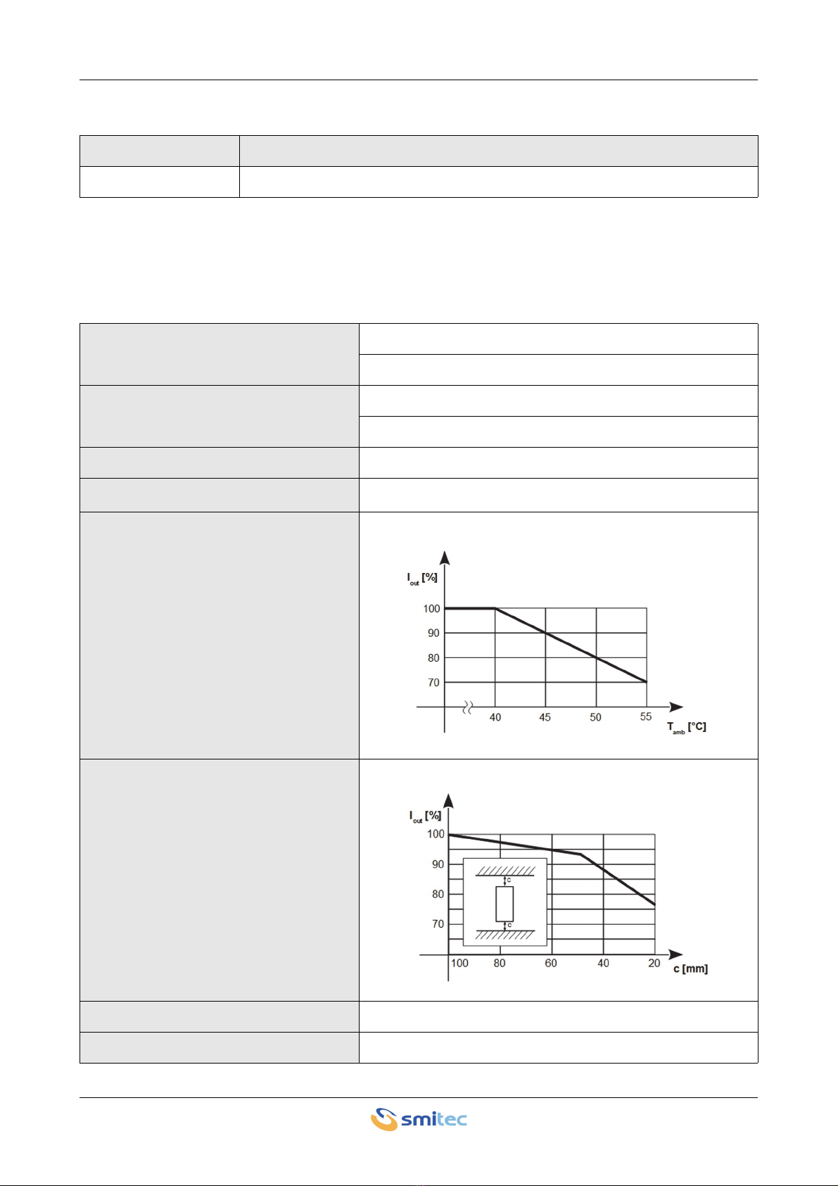
Output current derating as a function of
the ambient temperature
Derating current output as a function of
distance from obstructions
Air humidity during operation 5 ÷ 85% non-condensing
Storage temperature -25 ÷ +55°C
INVERTER COSMOS 3020 Installation, use and maintenance manual - EN
Ver. 1.07 11
4.3.2 Power supplies
4.3.3 Motor outputs
The inverter is characterized by two outputs motor:
Air humidity during storage 5 ÷ 95%
Air humidity during transport 5 ÷ 95%
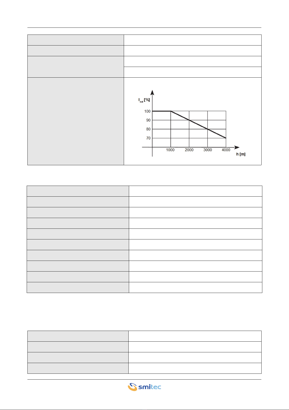
Maximum altitude
1000 m (on the sea level) at nominal output current
2000 m (on the sea level) with current derating
Output current derating as a function of
altitude
Main power supply voltage Single phase 230 Vac ± 15% 50/60 Hz
Distribution systems allowed TT,TN
Maximum short-circuit current 5 kA at the point of installation
Current max. main power supply 10 A RMS
24VDC auxiliary power supply voltage 24 VDC -15 ÷ +20%; ripple max 5% of the nominal value
Current max. auxiliary power supply 0.2 A (without connected I / O)
Output voltage Vs 24VDC (not regulated)
Current max. output Vs 1A (protected with self-resetting fuse)
Reverse polarity protection 24VDC Present
24VDC overvoltage protection Bidirectional Zener (Vz>30V)
Output voltage Three phase 0 ÷ 230 V
Output frequency 0÷128 Hz
Switching frequency 4/8/10/12/16kHz
Maximum output current 2.4 A RMS

INVERTER COSMOS 3020 Installation, use and maintenance manual - EN
Ver. 1.07 12
4.3.4 Digital inputs
Size maximum asynchronous motor 0.37kW / 1/2 HP (power to the crankshaft)
Active power deliverable 1 kW max.
Peak output current 12 A
Protections Phase-to-phase short circuit, overload, inverter over tem-
perature
Number of inputs 4
Type 24V digital inputs compatible with type 1 and type 3 according
to IEC 61131-2
Max frequency input signal 1 kHz

INVERTER COSMOS 3020 Installation, use and maintenance manual - EN
Ver. 1.07 13
4.4 Configurations / order codes
Up to date, we defined some standard configurations of inverters, with their order code and type number (4
figures, indicating the series, the maximum current and the release). These data are indicated on the inverter
label.
Order code Model Description
KZ010525 COSMOS 3020-FA 2X12Apk FlxIO ASYNC
TYPE **** -**
Series
3 = 3000
Peak current
01 = 14Apk – 0,75kW
02 = 2 x 12Apk – 0,37kW
15 = 15Apk – 2.2kW
25 = 25Apk – 5.5kW
50 = 50Apk – 7.5kW
HW Version
Sequential number, depending on the other figures
Communicatio
n
C = EtherCAT
D = Sercos II
E = Ethernet
F = FlxIO
N = None
R = RS485
S = Sercos III
T = Flextron
Type of motor controlled
A = Asyncronous
B = Brushless
U = Brushless + Asyncronous

INVERTER COSMOS 3020 Installation, use and maintenance manual - EN
Ver. 1.07 14
4.5 Model code
The specific features of a COSMOS 3020 inverter are defined by an alpha-numeric code printed on the device
label, near the MODEL code. Here is the code table:
MODEL ***** . ***** . *****
A ux ilia ry po we r
1 = 24Vdc
Main power
1 = 230÷480Vac 3PH
Maximum output current – Asyncronous motor power
1 = 15Apk – 2.2kW
2 = 25Apk – 5.5kW
3 = 50Apk – 7.5kW
Safe T orque Off (ST O) system
0 = Absent
1 = Present
Dynamic brake
0 = Absent
1 = Present
Brake resistor
0 = Absent
1 = 2,5kJ
2 = 5,0kJ
3 = 4,0kJ
4 = 0,8kJ
Encoder
0 = Absent
1 = Incremental 5V diff. phases and HALL TTL + Hiperface
2 = Hiperface
3 = Incremental 5V diff. phases and HALL TTL
4 = Incremental HTL 24V
5 = Incremental 5V diff. phases ande HALL TTL + Out
6 = Incremental 5V diff. phases andHALL TTL/diff.
Forced ventilation
0 = Absent
1 = 1x31,5CFM
2 = 2x31,5CFM
3 = 2x10.8CFM
Field bus physical layer
0 = Absent
1 = EIA-RS485
2 = Ethernet
3 = POF – Sercos II
VISIO 3000 support
* = Absent per Type 3150
* = Present per Type 3250/3500
0 = Absent
1 = Present
I/O Configuration
* = Absent
0 = Absent
1 = Type 1
2 = Type 2
Reserved
Reserved
Reserved
Rd

INVERTER COSMOS 3020 Installation, use and maintenance manual - EN
Ver. 1.07 15
4.6 Accessories
The COSMOS 3020 inverters are supplied with the complete set of detachable connectors for power and I / O
connections (where provided). The same connectors can be ordered separately as well as other accessories
not included in the inverter. Below is the list of order codes:
4.7 Electromagnetic compatibility (EMC)
The inverters comply with EN IEC 61800-3 requirements; they must be installed in the second environment,
category C3, on the following conditions:
• The connection between the inverter and the motor is made by means of an adequately sized shielded ca-
ble.
• The shielded cable must be connected to earth on both sides, with low RF impedance connection
• The motor type and size are suitable for the inverter
• The start-up is performed by technical engineers, according to the instructions of this manual.
Order code Article
KF101068 24VDC and I / O power connector (8x1)
These inverters are not designed for domestic environment (first-environment, according to
EN IEC 61800-3 standards). In this case, it will be necessary to install an additional mains
filter.
The integrated filter ensures compliance with the EN IEC 61800-3, only if a single inverter
is operating. The simultaneous operation of more than one inverter might increase the noise
level and might exceed the emission levels fixed by the standards. In this case, an additional
filter may be necessary.
INVERTER COSMOS 3020 Installation, use and maintenance manual - EN
Ver. 1.07 16
4.8 Mechanical specifications
4.8.1 Weight
The following table shows the weight:
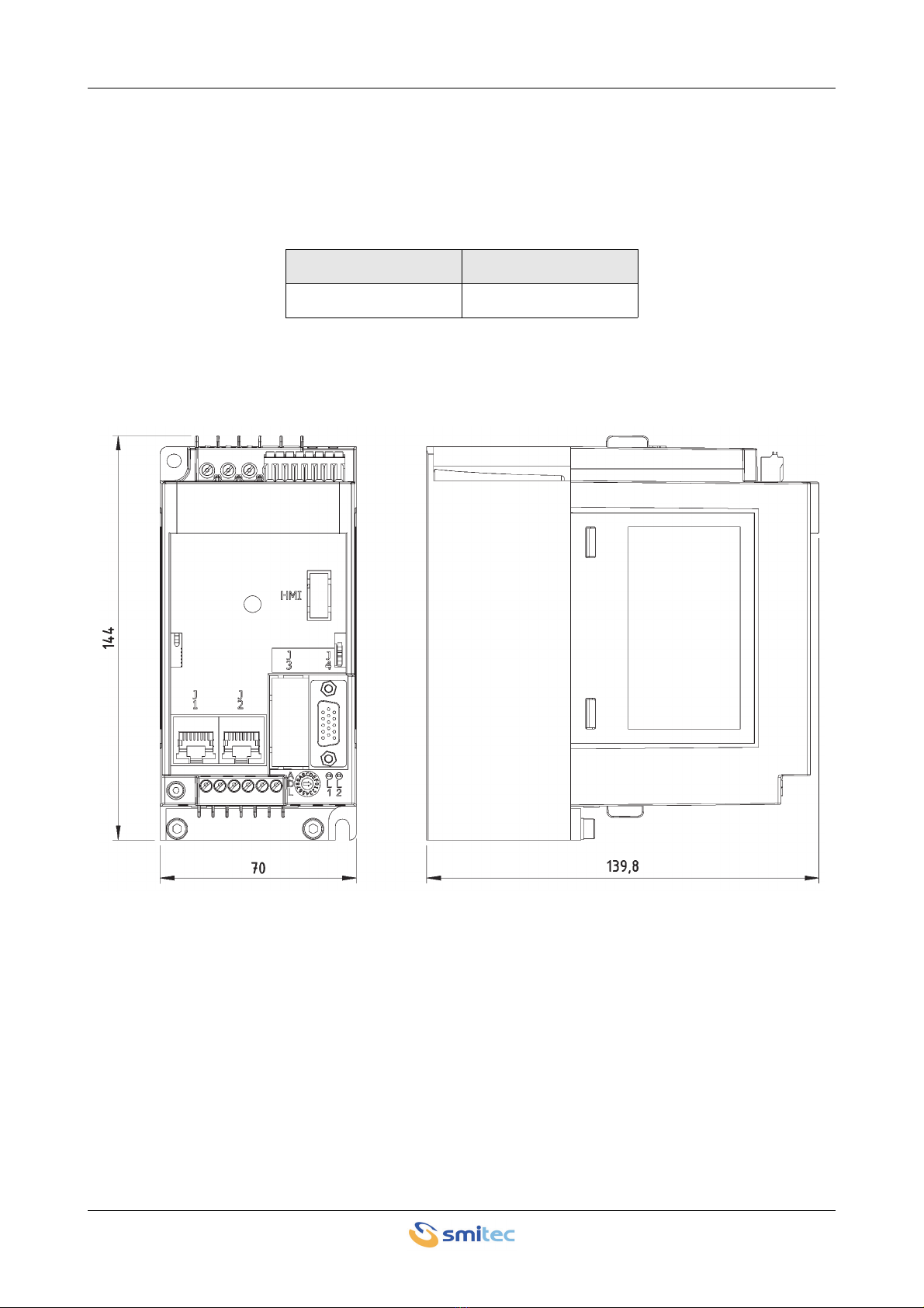
4.8.2 Model size
Type Weight (kg)
KZ010525 1.0 kg
INVERTER COSMOS 3020 Installation, use and maintenance manual - EN
Ver. 1.07 17
5 Installation and start-up
5.1 Preliminary operations
• Verify the perfect integrity of the equipment and its components.
• Make sure the installation manual is present.
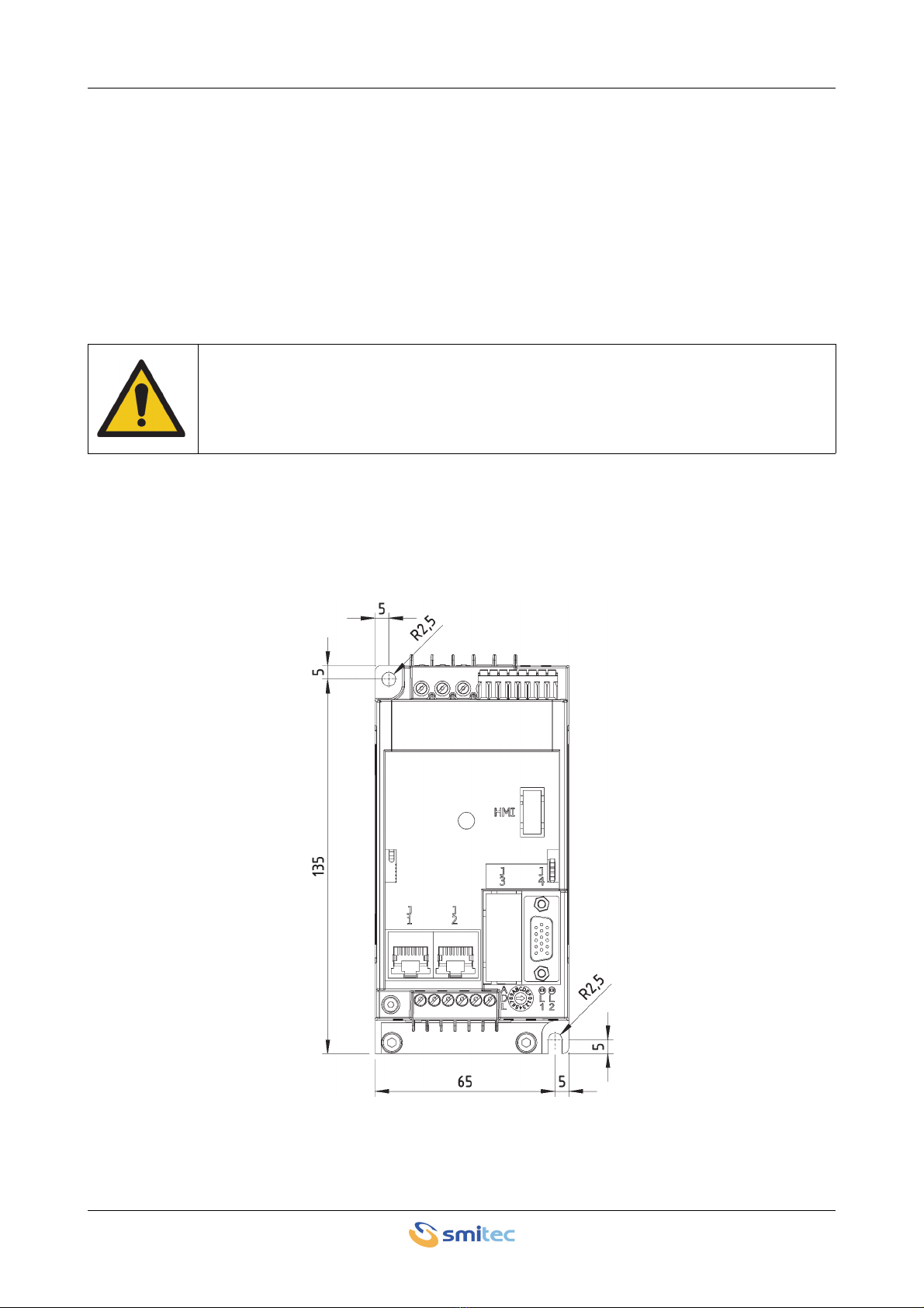
5.2 Positioning and installation
The device must be duly tightened to the metal wall of the electrical panel, by means of two screws M5 x 0.8
mm; if the operation generates vibrations, use retention washers (Grover or Belleville) or a thread-lock com-
pound. The following picture shows the front view and the recommended hole pattern.
The inverters COSMOS 3020 are designed for operating in closed electrical operating ar-
eas (as defined in the EN 61800-5-1 standard); installation outside an electrical panel is not
allowed.

INVERTER COSMOS 3020 Installation, use and maintenance manual - EN
Ver. 1.07 18
The inverters COSMOS 3020 generate a certain quantity of heat during operation; the electrical panel must be
able to dissipate it, in order to avoid an excessive temperature increase. A common solution consists in install-
ing cooling fans or a conditioner. In order to avoid dust ingress, which might degrade the dissipater perfor-
mance, it is recommended to use filters. The conditioning system must be adequately sized by taking into
consideration the total dissipation.
In order to ensure the performance characteristics, the inverters COSMOS 3020 must be installed exclusively
in vertical position (as indicated in the previous picture), leaving at least 100mm of obstacle-free space above
and below the inverter. If such conditions could not be fulfilled, apply a derating of the available current.
INVERTER COSMOS 3020 Installation, use and maintenance manual - EN
Ver. 1.07 19
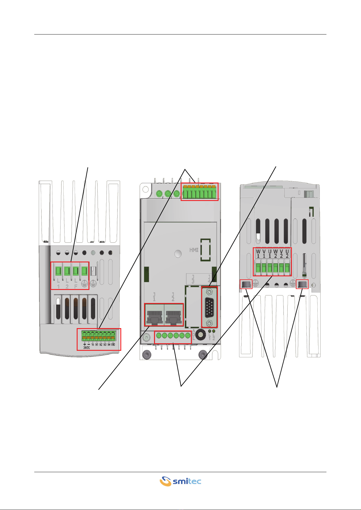
5.3 Electrical connections
The device described in this manual is equipped with screw terminal blocks for high voltage electrical connec-
tions (mains power supply, motor outputs, PE (Ground) protective conductor), while the extra low voltage con-
nections (24V power supply, 24V digital inputs) are made via detachable connectors.
The following image shows the arrangement of connectors and terminal blocks:
Encoder
Field bus Outputs motor
230VAC power supply and
PE (Ground) 24VDC power supply and digital inputs
FE/PE (Ground) motor
Top view Front view Bottom view

INVERTER COSMOS 3020 Installation, use and maintenance manual - EN
Ver. 1.07 20
5.3.1 Mains power
These are the connections of 230VAC supply.
WARNING
AVERTISSEMENT
The power wiring must be made by means of the 5-pole terminal board situated on the container top (see pic-
ture); it is the same for all releases.
These devices are designed to operate with TT or TN distribution networks, while with IT distribution networks
the device cannot be used, since the EMI filter present internally cannot be disconnected in any way. The fol-
lowing image shows the recommended connection diagram:
Risk of Electric Shock; wait at least No. 360 seconds (6 minutes) after disconnecting power.
Risque de choc électrique; attendez au moins 360 secondes (6 minutes) après la mise hors
tension.
230VAC mains power
Label Signal
L1 230VAC mains – phase 1
L2 230VAC mains – phase 2
LF NC
PE (Ground)
L1
L2
LF
Table of contents
Popular Inverter manuals by other brands


BARRON
BARRON EXITRONIX Tucson Micro Series installation instructions

Baumer
Baumer HUBNER TDP 0,2 Series Mounting and operating instructions

electroil
electroil ITTPD11W-RS-BC Operation and Maintenance Handbook

Silicon Solar
Silicon Solar TPS555-1230 instruction manual

Mission Critical
Mission Critical Xantrex Freedom SW-RVC owner's guide

HP
HP 3312A Operating and service manual


