Smith & Larson Audio Woofer Tester User manual

Speaker Tester Quick Reference Guide v1.4 1
GETTING STARTED
Do not plug the Speaker Tester into your computer’s USB Port before you have
installed the software
Your Speaker Tester comes with the following items:
Speaker Tester Hardware
CD-ROM containing Speaker Tester software
1 USB A/B cable
2 RCA Y-cables
1 10-ohm 1/4 watt calibration resistor
Low-power banana/alligator test leads
1 Measurement microphone and cable
SPEAKER TESTER QUICK REFERENCE GUIDE

2 Speaker Tester Quick Reference Guide v1.4
A. Getting to know your Speaker Tester
Speaker Tester Front Panel
The front of the test measurement box contains the line-in and line-out ports as well as the
phantom powered microphone inputs as shown below:
Speaker Tester Back Panel
The back of the measurement box contains a 5V power port, USB port, a high-power test
port and a low-power test port:
* The high-power test port can be enabled with an upgrade to the Woofer Tester Pro. See the upgrade offer on our website for more
details.
Line-in
port
Line-out
port
Power LED
Phantom powered microphone inputs
High-power test port
(not enabled*)
Auxiliary 5V port
for low power
USB hosts
(not required in
most cases)
USB port
Low-power
test port

Speaker Tester Quick Reference Guide v1.4 3
B. Installing the Software
1. Insert the CD-ROM into your computer. If the installation process does not start
automatically, run setup.exe from the CD-ROM. This will start the software install wizard:
2. Click Next. The next dialog box shows the license agreement. Please read it and select
“I agree” if you concur and then click Continue to proceed with the installation
3. Next, select an existing directory using Browse or create a new one by typing a name in
the text box. By default, a WTPRO directory gets created on your C: Drive and you’ll be
asked if you want to create a new directory. Click OK to continue
4. The last step in the software installation shows you the latest readme.txt file and asks if
you want to add a desktop icon and an entry in the Windows
Start
Program
. Select
the appropriate options and click Finish. The software installation is now complete.
4 Speaker Tester Quick Reference Guide v1.4
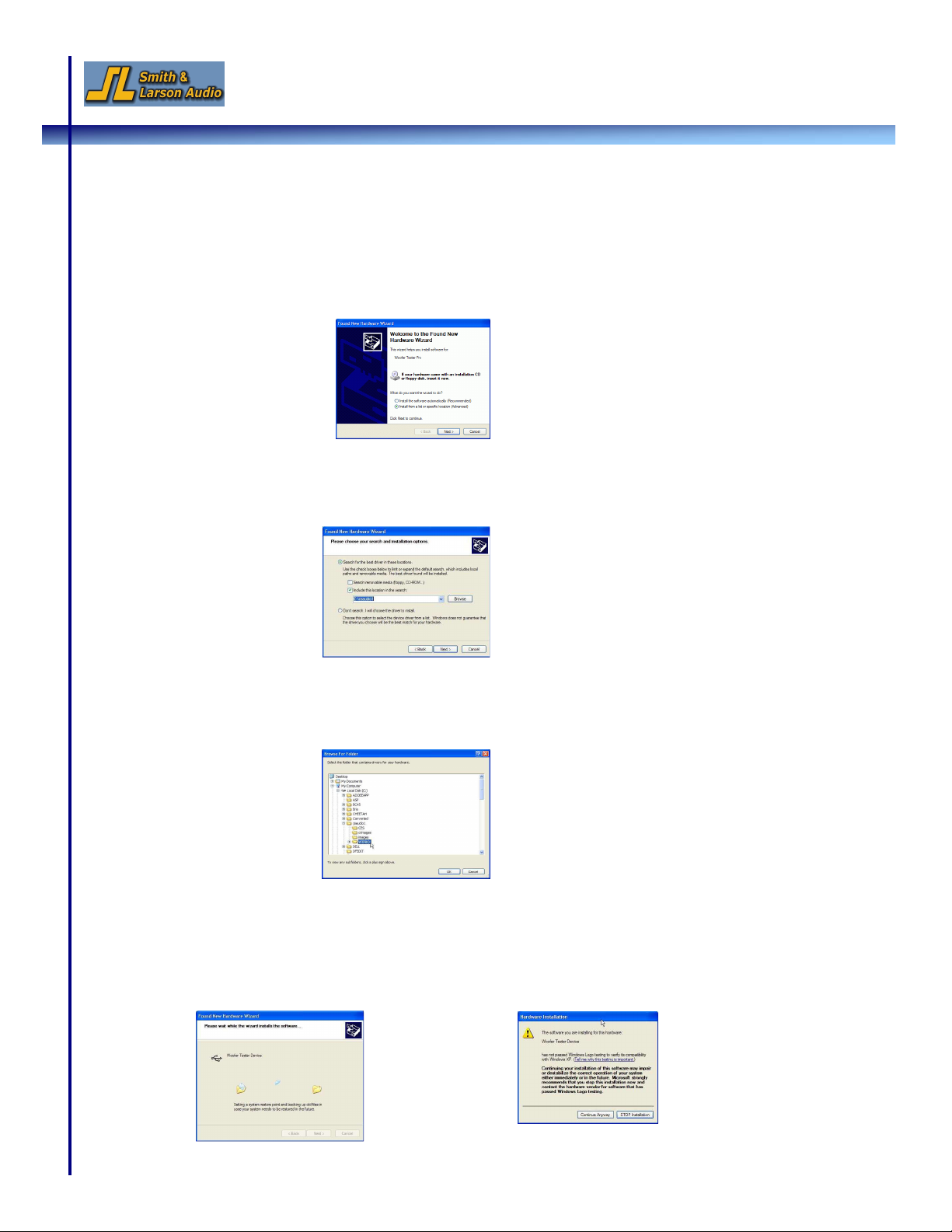
C. Setting up the Hardware
1. To setup the hardware, connect the USB cable to your computer’s USB port and to the
Speaker Tester’s USB port. Windows will indicate that it has detected new hardware and
the following dialog box pops open:
2. Select the “Install from a list of specific location (Advanced)” option and click Next
3. The following dialog box appears:
4. Click the Browse button
5. In the file dialog box that opens, select the WTPRO directory that you created earlier and
click OK
6. Click Next
7. If you are using Windows XP, a warning message about Windows Logo testing will
appear next. Click Continue Anyway to continue the installation

Speaker Tester Quick Reference Guide v1.4 5
8. Once the files are copied, click Finish to complete the installation
9. You will see a system tray message that your new hardware is installed and the
hardware setup is now complete.
Additional Steps for Windows Vista Users
When Windows Vista installs the ‘USB Audio Device’ driver, the initial default will be set for 1
channel 22 kHz. This must be changed for the Speaker Tester to operate properly. The changes
made here may revert back if the operating system is updated, or a new audio device is installed.
1. From the Start menu, open the Control Panel and select ‘Hardware and Sound’. The
Speaker Tester will be identified as using a ‘USB Audio Codec’.
2. Click on the Recording tab and look for the Microphone that uses the ‘USB Audio Codec’.
3. Click on the microphone properties, and then select the ‘Levels’ tab.
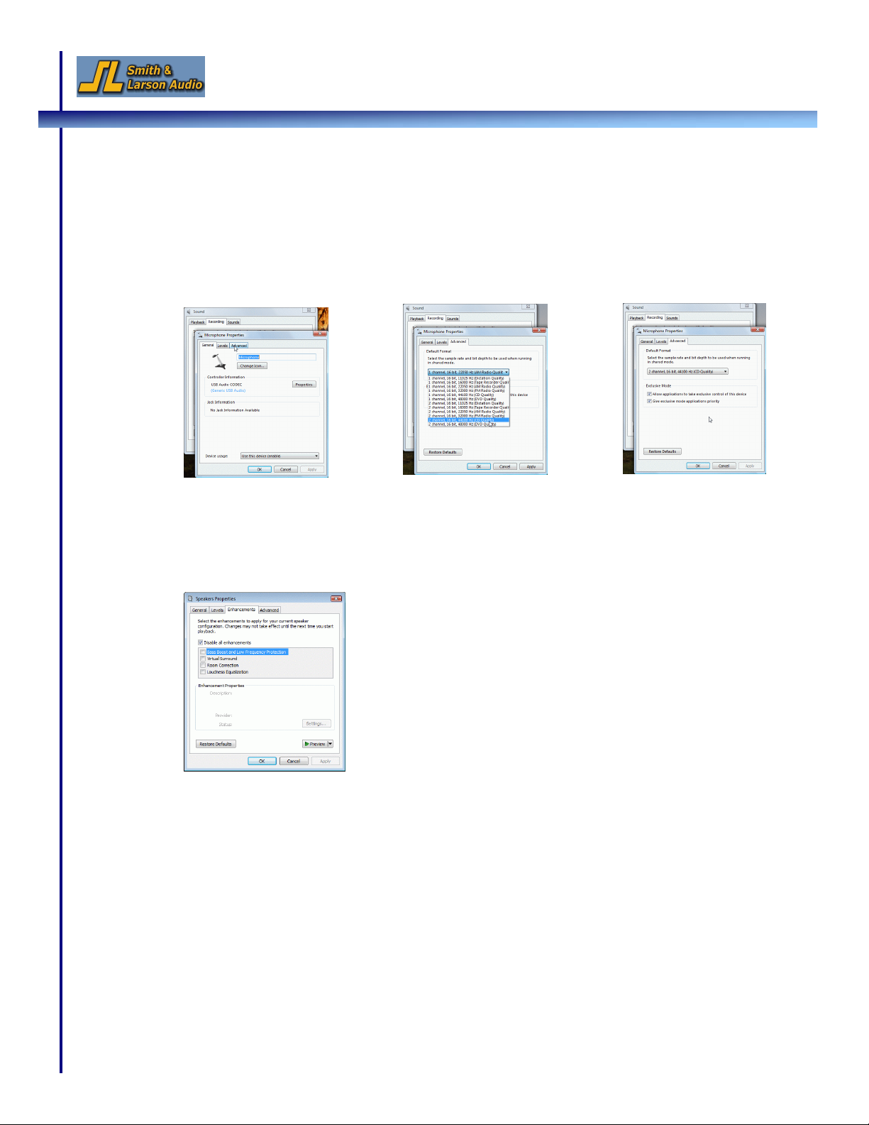
6 Speaker Tester Quick Reference Guide v1.4
4. Next, click on the ‘Advanced’ tab and change the settings to 2 channels, 44100 Hz
sampling rate. Select the two ‘Exclusive Mode’ check boxes giving the tester application
control of the device. Click OK.
5. Repeat Step 4 for the ‘Playback’ tab (2 channel 44100 Hz sampling).
6. Go to the ‘Enhancements’ Tab and make sure that the ‘Disable all enhancements’
checkbox is selected.
7. Make sure that the Playback, Record and Speaker Tester sampling rates all match.
44100 Hz is the recommended sampling rate for Vista and is the default setting on the
Speaker Tester. Sampling rates are changed in the
Options
pull-down menu or from the
‘Comp & Size’ tab in the Setup Control window.
Speaker Tester Quick Reference Guide v1.4 7
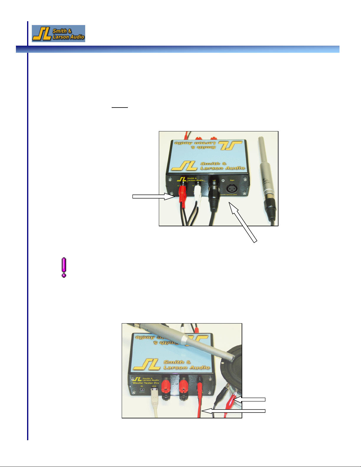
The RCA Y-jacks are normally left connected. The Y-jacks provide the physical line-out to
line-in loop back needed for using the line signal as a reference. Remove these if you want
to analyze a line level device such as a preamp.
D. Demo 1: Conducting a Simple Electrical and Acoustic Test
The configuration shown requires minimal hardware and verifies functionality for both the
low level electrical and acoustic demos. An external amplifier is not called for, because the
low level port has enough output to drive a small speaker. Adding an external amplifier would
be the next step! Note: You will want to keep the Y-jacks connected.
1. Plug the RCA Y-cables into the Line-out and Line-in ports to create an external loopback
path.
2. Connect the microphone(s). (Demo 2 will use the left microphone.)
3. On the backside of the Speaker Tester, connect the test leads to the low power test port
and hook the alligator clips up to a test driver or speaker
Connect the first RCA Y-
cable to the upper line-in
and line-out ports and
connect the second cable
to the two lower ports
Connect the microphone
(for next in-air response test)
Connect the test leads
to the low power test
port and to the driver
8 Speaker Tester Quick Reference Guide v1.4
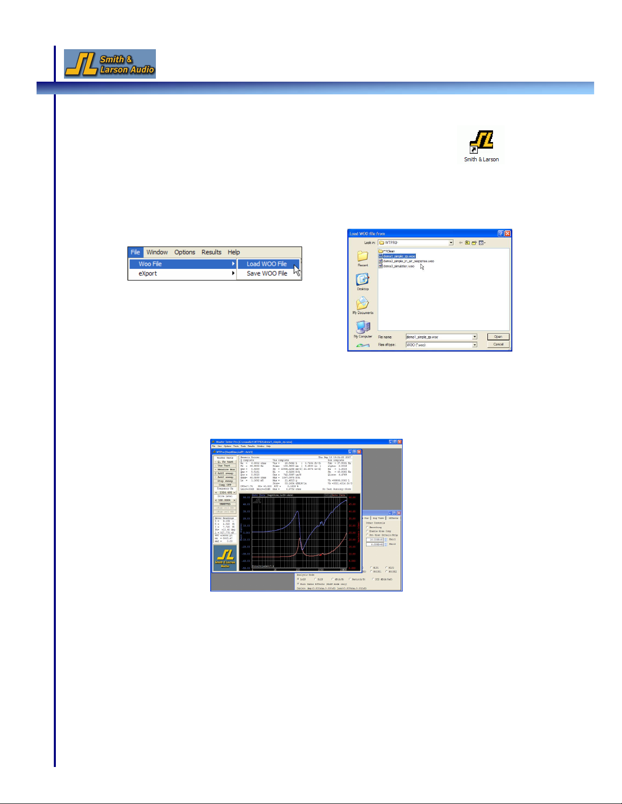
4. Double-click the Smith&Larson.exe icon on your desktop to launch the
Speaker Tester application
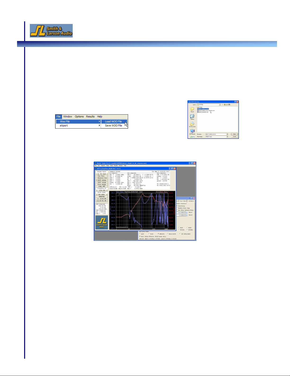
5. Next, open the Demo 1 file by selecting
File
Woofile
Load Woofile
from the menu
bar. In the file open dialog box that pops up, select the file called
“demo1_simple_zp.woo” and click Open
6. Your screen now displays the WT Control window in the front and the Setup Control
window in the back. You can hear the Chirp signal the tester is using to conduct the
electrical test:
Speaker Tester Quick Reference Guide v1.4 9
E. Demo 2: Performing an In-Air Test
To conduct an In-Air test, leave the current driver connected. The low power port acts as a low
power amplifier and this setup is sufficient to see the response.
1. Open the Demo 2 file by selecting
File
Woofile
Load Woofile
from the menu bar. In
the file open dialog box that pops up, select the file called
“demo2_simple_in_air_response.woo” and click Open
2. Your screen displays the WT Control window in the front and the Setup Control window
in the back. The graph displays the response of the speaker:
10 Speaker Tester Quick Reference Guide v1.4
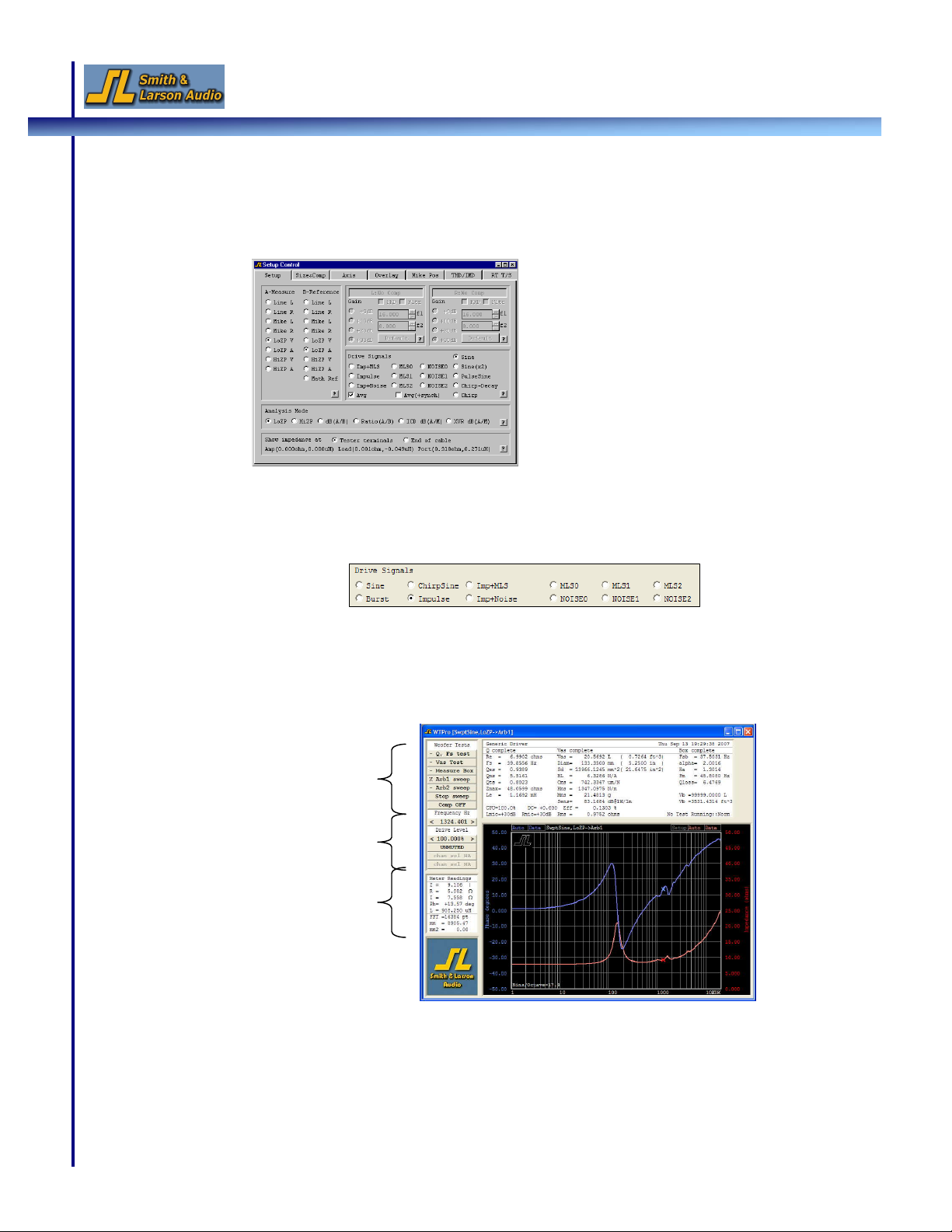
F. Changing Analysis Modes and Drive Signals
1. Click on the Setup Control Window to bring it to the front. If this window is not open, go
to the
View
menu and select
Setup Control
2. In this window, you can configure your measurement settings and analysis modes. For
example, click on Impulse to change the drive signal:
3. To change the drive level, activate the WT Control window. On the left-hand side are the
test and output control buttons as well as the real-time meter window:
4. Click the middle of the drive level button to bring up the drive level dialog box and enter
a new drive level. Click on the left or right of the button to adjust the level up or down.
Real-time meter window
Test buttons
Output control buttons
Speaker Tester Quick Reference Guide v1.4 11
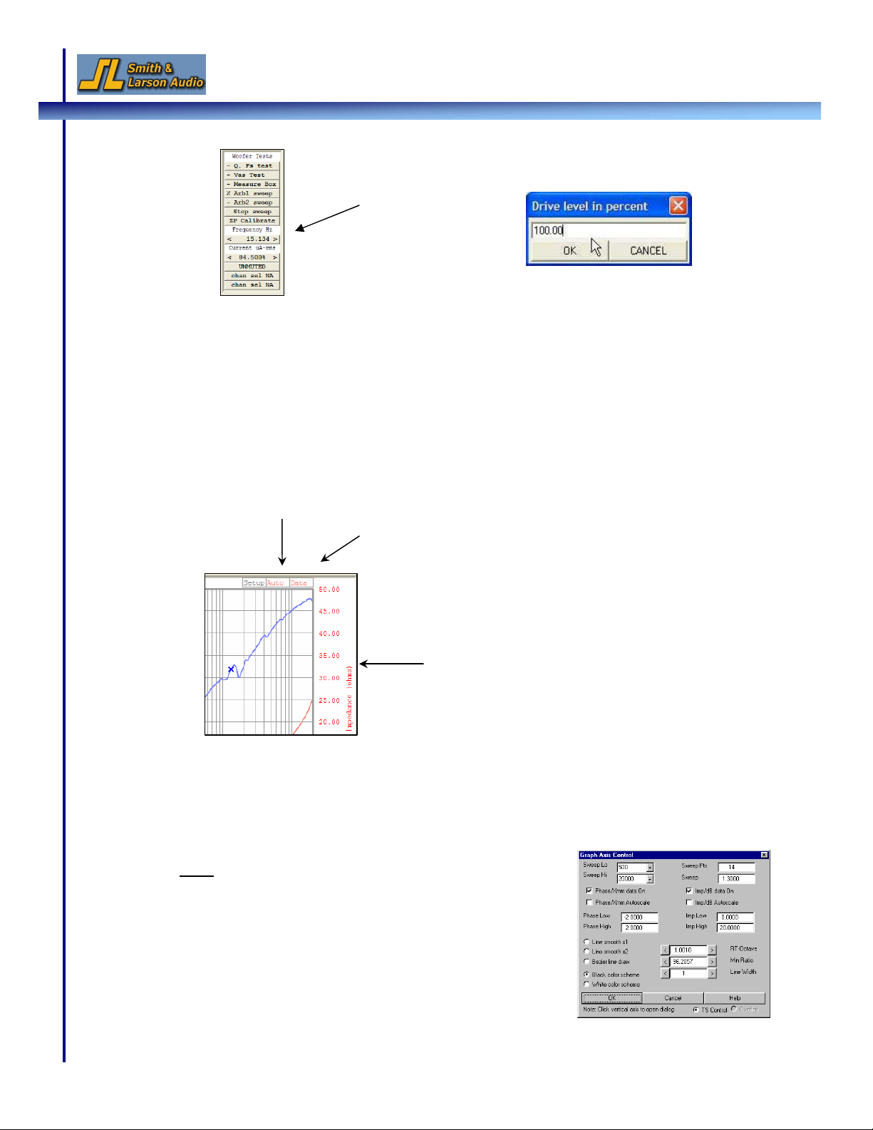
G. Modifying the Signal Graph and Current Measurement Frequency
1. Autoscale mode on/off:
By default, the scale of the db (response) and phase axes are set to autoscale and are
continually resized. To turn autoscale off, click the Auto button in the graph. Click it
again to turn autoscaling back on:
2. Changing the Frequency Range (X-axis):
a. Click along the axis labels (left or right side) to bring up the Graph Axis Control
window and set the new axis ranges:
Note: Autoscaling, discussed previously, can also be turned
on and off in this window by setting the Phase/Disp Auto
and Imp/db Auto options.
Drive level button
Drive level dialog box
Auto button turns autoscaling on and off
Clicking along the axis opens the Axis
control dialog box
Data button turns line draw on and off
12 Speaker Tester Quick Reference Guide v1.4
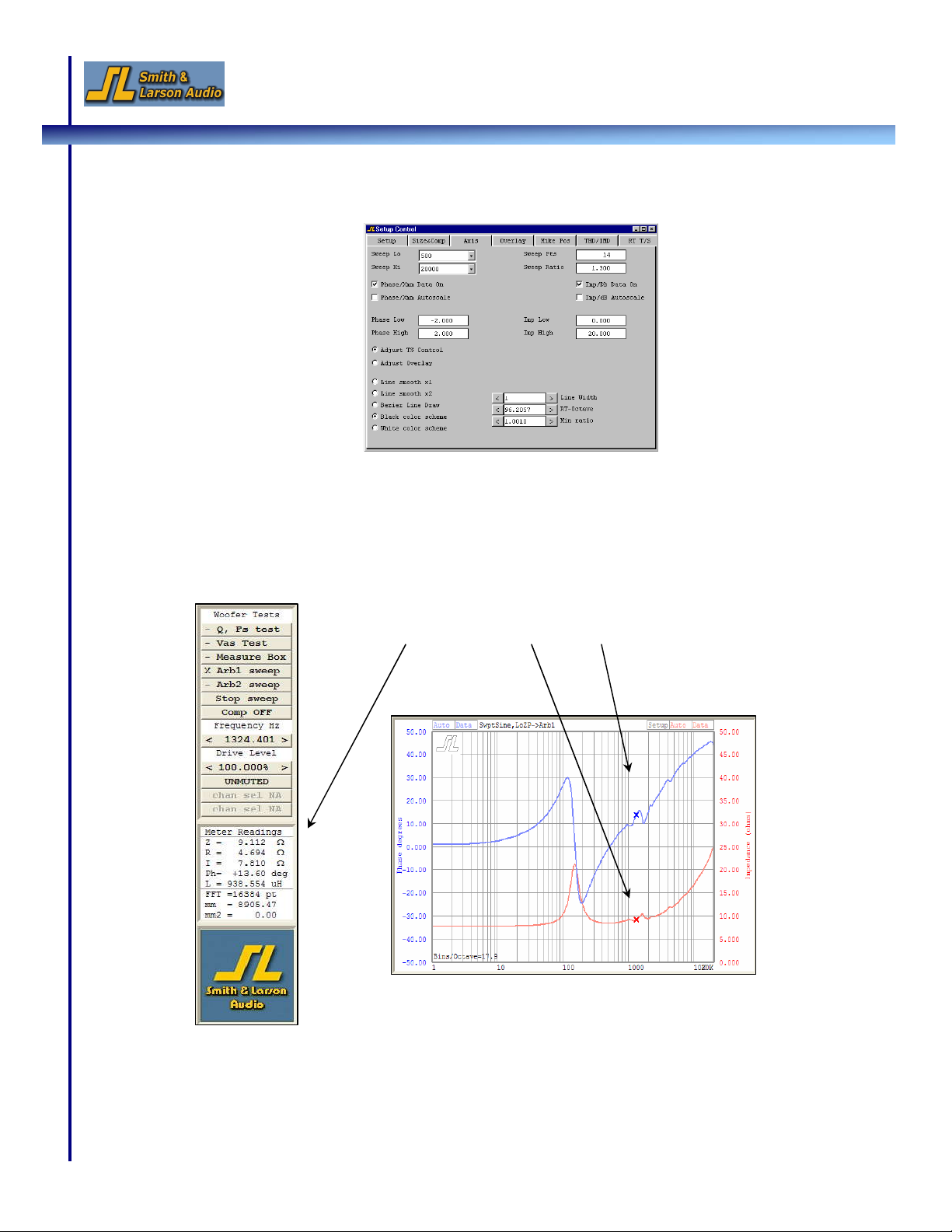
b. The axis ranges can also be set in the Setup Control Window under the Axis tab:
3. Changing the Real-time Measurement Frequency:
A left mouse click anywhere inside the graph changes the measurement frequency
displayed in the real-time meter window. This frequency is indicated by the two Xs in the
graph. If the signal mode is continuous sine, this also sets the sine wave frequency.
Real-time meter shows impedance and phase at user selected frequency
Speaker Tester Quick Reference Guide v1.4 13
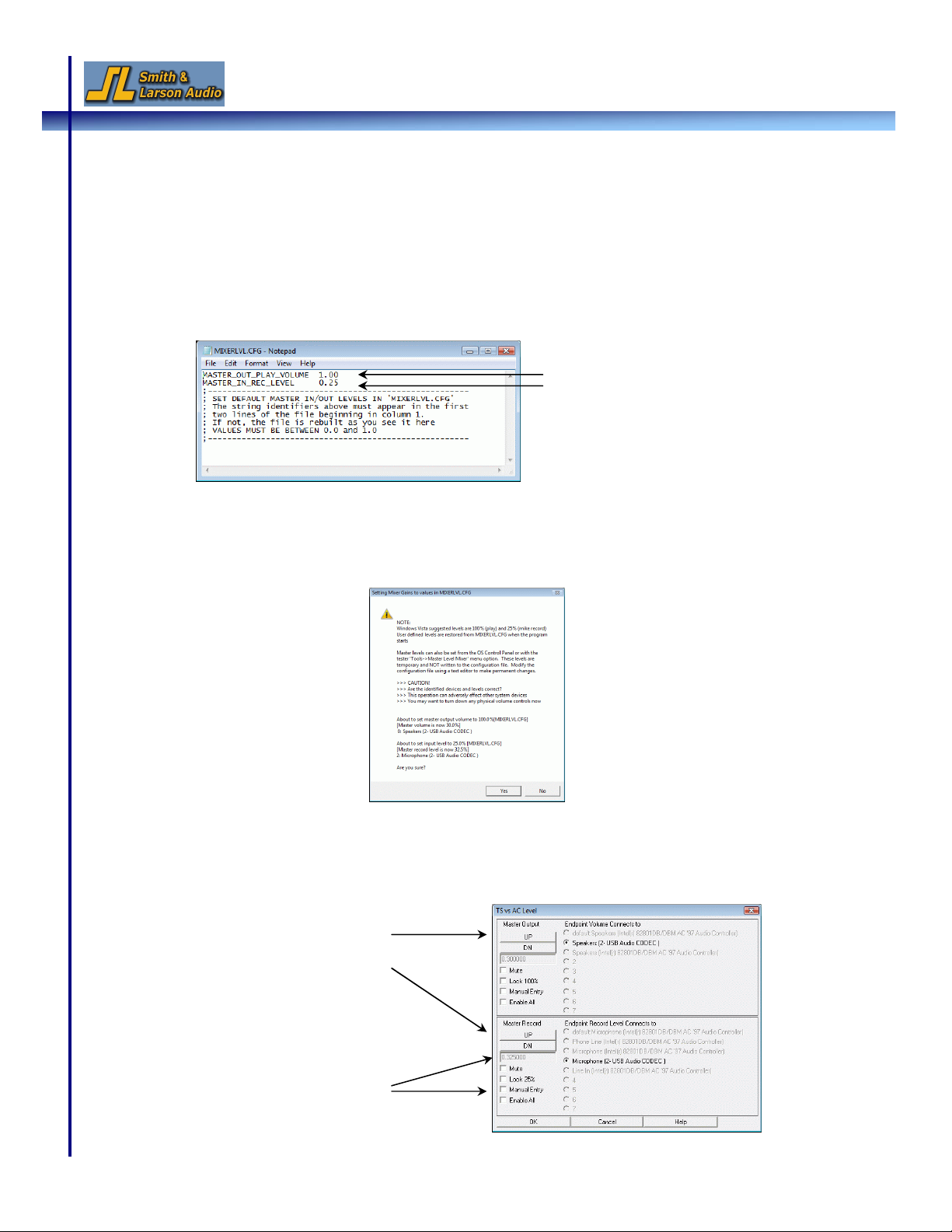
H. Adjusting the Mixer Level (Windows Vista Users Only)
1. Windows Vista allows users to set different master volume levels for the various audio
devices connected to the computer. By default, Vista requires the (microphone) input
level to be set to 25% and the output to 100%. These settings are stored in a
configuration file called “MIXERLVL.CFG” located in the tester installation directory and
can be configured by editing this file (you should not need to change this).
2. If the startup mixer settings do not match the levels specified in the “MIXERLVL.CFG”
file, the message shown below appears asking you to confirm the change. The current
mixer levels can also be reset to the values in “MIXERLVL.CFG” by selecting the
Tools
Auto-Set
menu option.
3. The input and output levels can be temporarily changed for the session via the
Tools
Master Level Mixer
menu option. Note that these changes revert back to the levels set in
the MIXERLVL.CFG after you close the application.
Edit volume settings in MIXERLVL.CFG file.
Values are in % and range from 0 to 1.
Adjust the volume with
the UP and DN buttons
Adjust the volume
by selecting the
‘Manual Entry’
checkbox and
entering a value

14 Speaker Tester Quick Reference Guide v1.4
This concludes the quick reference guide for the Speaker Tester.
I. Reference Materials & Support
Please refer to the User Guide, which can be downloaded from the Support section of our
website, for an in-depth description of all the features contained in the Speaker Tester.
Additional help topics can be found in the FAQ section as well as the User Forum on our website.
For customer support, please email us at tech@woofertester.com or call +1 781-259-1804.
We hope that our product will help you succeed in your venture and would love to hear from
you,
Smith & Larson Audio
This manual suits for next models
1
Table of contents
Other Smith & Larson Audio Test Equipment manuals


