SECTION 1 - THEORY OF OPERATION
1-1
1-1 GENERAL
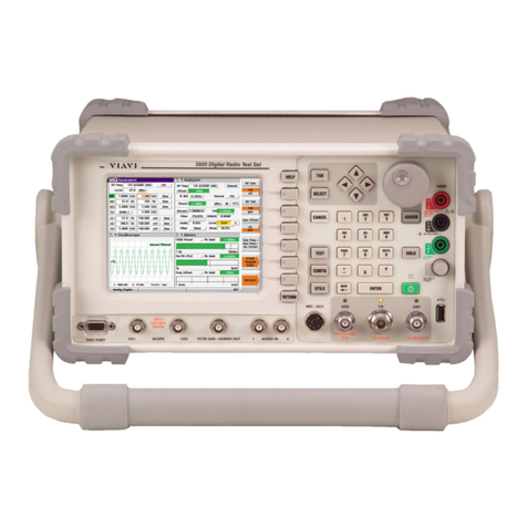
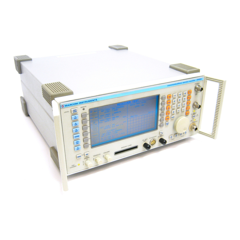
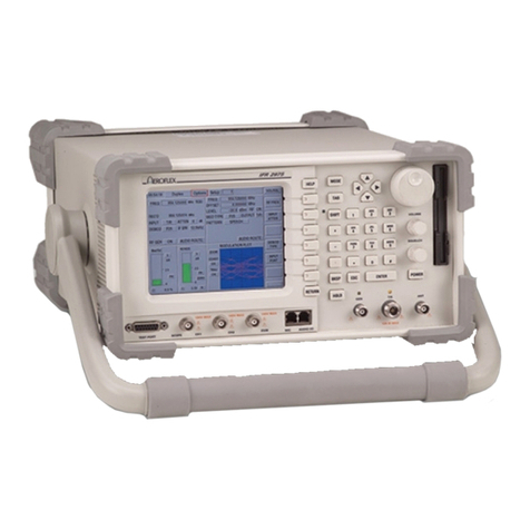
The 2975 digital radio test platform integrates over 20 radio-testing instruments into a single user-
friendly instrument that offers the interconnectivity normally expected from a personal computer.
The 2975 digital test platform, created with modular design, is simple to support and upgrade. The
2975 provides comprehensive transmitter and receiver testing, while the full-range spectrum analyzer
and tracking generator make possible base site component testing. The dual channel oscilloscope
and internal DEMOD scope provide comprehensive viewing of signals.
This following sections, System Overview and Module Overview, provide the maintenance technician
with a concept of how the 2975 operates.
1-2 SYSTEM OVERVIEW
RECEIVE SYSTEM OVERVIEW
The 2975 is capable of receiving modulated or unmodulated signals ranging form 1 MHz to 2.7 GHz.
Signals are received through the Power Termination Assy at the ANT Connector (low power signals,
<-10 dBm) or T/R Connector (high power signals, >-10 to +50 dBm). A diode detector serves to
measure RF power applied to the T/R Connector. The ANT Connector and GEN Connector are
protected from high power levels by a limiter circuit. Refer to the Generate System Overview for
more details on the GEN Connector. The RF signal is routed to the Receiver Assy.
The Receiver Assy has selectable attenuators and provides reference signals of 10, 40, 80 and
400 MHz to the system. External 10 MHz I/O is routed from the Receiver Assy to the Rear Panel
Assy. In the Receiver Assy, the incoming signal is converted to an IF (immediate frequency) of
10.7 MHz and signal conditioning is started. The 10.7 MHz IF signal is passed on to the Video/IF
PCB Assy.
The IF/Video PCB Assy has selectable 10.7 MHz IF filtering of 30 kHz, 300 kHz and 6 MHz. Both the
CAI (Common Air Interface) PCB Assy and the IF/Video PCB Assy work together to provide the AGC
(automatic gain control) for the Receiver Assy. The CAI PCB Assy sends data to the IF/Video PCB
Assy to increase or decrease the gain automatically, providing the correct level to the CAI PCB Assy.
The IF/Video PCB Assy also is responsible for Analyzer resolution bandwidth filters in the “Look and
Listen” mode of 300 Hz, 3 kHz and 60 kHz. When the dedicated Analyzer mode is selected, all
combinations of IF filtering are used to provide a fully functional Spectrum Analyzer. Additional
functions of the IF/Video PCB Assy are: 10.7 MHz IF output to the Rear Panel Assy, Video output to
the Rear Panel Assy and IF Count to the Multifunction PCB Assy. The final destination of the
10.7 MHz IF signal is routed to the CAI PCB Assy.
The CAI PCB Assy receives the 10.7 MHz IF signal and digitally performs the demodulation process.
Demodulation types include FM, AM, P25 and P25Encr. During the demodulation process, the signal
is measured for correct power strength. If the incoming power is incorrect, data is provided back to
the IF/Video PCB Assy for AGC control as previously discussed in the IF/Video PCB section above.
The CAI PCB Assy provides digitally demodulated signals to the system for meter functions such as:
Receiver Level Meter, Deviation Meter, C4FM Meter, Demod Output, Internal Demod Scope and
Speaker. Other CAI PCB Assy functions are discussed in the Generate System Overview.


