3
Warning
●Before operating this instrument, familiarize yourself with all instructions outlined
in this manual.
●The instrument must only be used by suitably trained competent parsons.
●Always check to make sure that the function switch is set to the proper position.
●When making measurements, use CAUTION as dangerous voltages may be
present in normally safe areas.
●When making measurements, do not touch any conductive parts of the
equipment under test. For safe operation, the use of rubber insulation glove
is recommended.
●The instrument should not be used if any part of the instrument is damaged.
The CT sensor must be good order with no broken or cracked insulation.
●To avoid electrical shock, use CAUTION when working above 60V DC or 25V
AC rms. Such voltages pose a shock hazard.
●Do not disassemble the CT sensor or instrument.
●Do not remove the stopper in normal operation, it may cause the serious
problem of the instrument.
POSSIBLE ELECTRICALSHOCK
●If excessive current is applied to the CT sensor, the instrument will be heated
and damaged. Use the instrument within the rated current.
●This instrument is designed to measure the grounding line of arrester, do not
measure the live power line.
●Do not use the instrument, if any part of the CT sensor is damaged.
●Do not measure the uninsulated conductor.
4
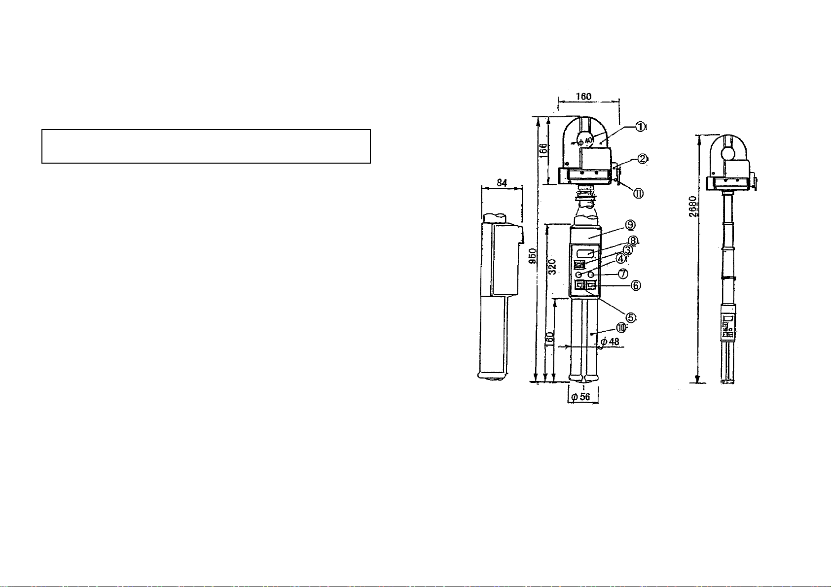
3. SPECIFICATIONS
CT Sensor
CT max. opening size : φ37mm
Opening/closing of the jaw : Motor operation
Withstanding voltage : AC 2300V, 1 minute (between the core of CT and CT
outer case)
Measuring and display unit
Measuring function : Leakage current, harmonic current (Fundamental & 3rd
harmonics)
A/D converstion : Dual slope integration mode
Measuring range : AC 0-300μA/3mA/30mA(3range manual)
Input frequency : 45-60Hz (Fundamental frequency)
AC conversion : AC coupled true rms responding
Display : LCD, max. 3200 count
Sampling : 2 times/sec.
Over indication : “OL” mark on LCD
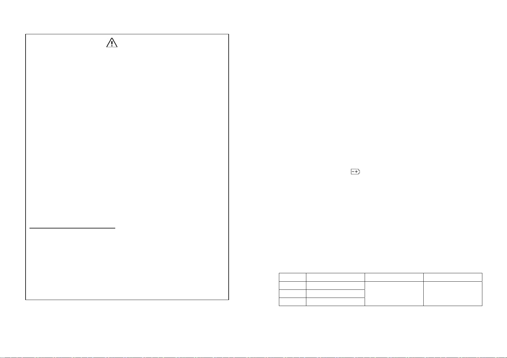
Low battery indication : “ ” mark on LCD
Data hold indication : “DH” mark on LCD
Auto power off function : Approx.10 minutes later after power on
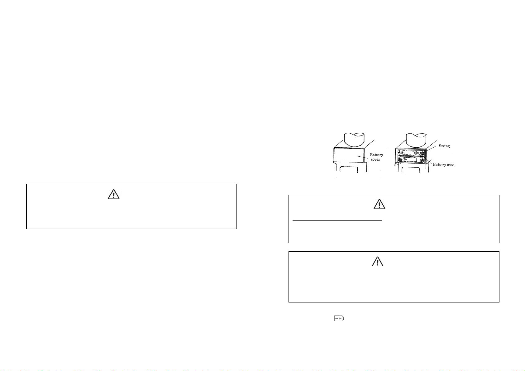
Power supply : AAsize alkaline battery × 4
Limitation of circuit voltage : Less thanAC500Vrms
Operating temperature : 0-40℃, less than 80%RH
(Without condensation)
Storage temperature : -10~60℃, less than 70%RH
(Without condensation)
Dimensions : 160(W)×950(L)×84(D)(When retracted)
: 160(W)×2680(L)×84(D)(When stretched)
Weight : Approx.2.6kgs
AC Current
Accuracy (23℃±5℃, less than 80%RH)
Range Resolution Accuracy(45~65Hz) Max. input Current
300μA 100nA(0.1μA) ±1.2%±8digit
40Arms
3mA 1μA(0.001mA)
30mA 10μA(0.01mA)
Crest factor : <3 (0-50% of the range)
<2 (50-100% of the range)