Smith’s Environmental Products STERLING E 2kW Operation manual

INSTALLATION DIAGRAMS
All dimensions given are mm.
NOTE: The bottom fixing holes must be 2.07 metres (81½”) from the floor level to obtain
the correct mounting height of the heater appliance.
IMPORTANT: A clearance distance of 1.5 metres downwards from the underside of the
heater appliance and 1.5 metres outwards from the mounting surface must be maintained
for correct operation and air distribution.
Products with the symbol (crossed out wheelie bin) cannot be disposed as household waste. Old
electrical and electronic equipment should be recycled at a facility capable of handling these products
and their waste byproducts. Contact your local authority for details in locating a recycling facility
nearest to you. Proper recycling and waste disposal will help conserve resources whilst preventing
detrimental effects on our health and the environment.
Smith’s Environmental Products Ltd
Blackall Industrial Estate
South Woodham Ferrers, Chelmsford, Essex. CM3 5UW
Tel: 01245 324900 Fax: 01245 324422 After Sales: 01245 324560
Website: www.smiths-env.com E-mail: sales@smiths-env.com
04-0811 Oct 06
STERLING E 2kW & 4kW
INSTALLATION & USER GUIDE
330 640150150
301 611164.5164.5
225
76
215
78.5
STERLING E4Kw
STERLING E2Kw
OUTLINEOFINSTALLATION CLEARANCES
DIAGRAM1
DIAGRAM2

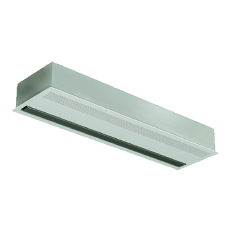
This heater appliance is intended for use as a warm air curtain and is to be mounted on the wall
above doorways or along a wall. It is to be mounted with the underside a maximum of 2.1 metres
above floor level. It can be mounted directly to a wall surface to provide a near vertically
downward air discharge or on angled mounting brackets (supplied) to provide an air discharge
angled 25° from downward. If exceeding 3 metres there will be a reduction in performance.
THE STERLING “E” PC (PULL CORD MODEL) SHOULD BE USED IN
BATHROOMS OR SIMILAR HIGH HUMIDITY AREAS. DO NOT USE THE
STANDARD 2 kW & 4kW.
INSTALLATION INSTRUCTIONS.
Preparation.
a) Ensure the mounting surface is flat, sound and capable of safely supporting this heater appliance.
The surface must not be of a flammable material.
b) Check for sufficient installation clearances around the appliance to enable correct operation and
service access. See Diagram 1 on back page.
c) Wall fixing points: Screws and wall plugs used must be suitable for the wall type and
construction material.
d) Remove the heater appliance front cover fixing screws (5 on the 2kW model, 7 on the 4kW
model). Remove the packaging containing the two angled mounting brackets and four screws. Store
the brackets package, the cover and cover fixing screws in a safe place until required. Note: The
brackets have four fixing screws included; these are intended only for securing the heater appliance
to the brackets.
To mount the heater appliance directly to the wall.
1) Drill four fixing holes as shown in Diagram 1 on back page according to model type.
2) Plug all four holes and apply fixing screws to the top two holes. Leave the underside of the
screw heads projecting approx. 10 mm.
3) Lift up the heater appliance and hold it with the switches at the bottom, and the mains electrical
cable at the top left corner.
4) The back panel has two keyhole slots - align and engage these with the two screws in the wall.
When the screws are at the top of the slots they are to be tightened, then apply the other two screws
in the vacant plain holes 76mm beneath the keyhole slots. Ensure all four screws are fully engaged
and secure. Ensure the heater appliance back panel is flat without distortion. If the wall is uneven,
add packing behind the fixing points until the heater appliance back panel is flat.
5) Replace the front cover and secure with the fixing screws described in d) above. Discard the
angled mounting brackets and the associated four fixing screws.
To mount the heater appliance on the angled mounting brackets.
6) Drill four fixing holes as shown in Diagram 2 on back page, according to model type.
7) Plug all four holes and apply fixing screws to the top two holes. Leave the underside of the
screw heads projecting approx. 10 mm.
8) Note: The brackets are paired left and right hand. Place a bracket via the keyhole slot on each
screw with the bracket flanges pointing inwards. Whenthe screws are at the top of the slots, apply
the other two screws in the vacant holes 68mm beneath the
keyhole slots. Tighten all four screws.
9) Locate the four screws for fixing the heater appliance to the brackets, and place one in each of
the top screw clips in the brackets. Leave the screw heads projecting approx. 10 mm.
10) Lift up the heater appliance and hold it with the switches at the bottom, and the mains electrical
cable at the top left corner.
11) The back panel has two keyhole slots - align and engage the two screws in the mounting
brackets. When the screws are at the top of the slots they are to be tightened and then apply the
other two screws in the vacant plain holes 68 mm beneath the keyhole slots.
Ensure all four screws are fully engaged and secure. Ensure the heater appliance back panel is flat
without distortion. If the wall is uneven, add packing behind the bracket fixing points until the
appliance back panel is flat.
12) Replace the front cover and secure with the fixing screws described in d) above.
Electrical Connections.
All electrical connections and installations must comply with BS7671, 1992, and the I.E.E.
Regulations. Check the voltage stated on the heater appliance is correct for your supply. If in doubt,
consult a qualified electrician.
Connect the three core electrical cord to a fused switched spur, fused 10A for the 2kW model. The
4kW model should wired via a 20 Amp double pole isolation switch back to a dedicated fuse in the
main fuse board. As the colours of the wires in the mains lead of this appliance may not correspond
with the coloured markings identifying the terminals in your outlet, proceed as follows. The
GREEN-AND-YELLOW wire must be connected to the terminal in the outlet marked with letter E
or by the Earth symbol or coloured GREEN or GREEN-AND-YELLOW.
The BLUE wire must be connected to the terminal marked with letter N or coloured BLACK.
The BROWN wire must be connected to the terminal marked with letter L or coloured RED.
Unit Operation.
The three control switches provide the following functions:
STERLING E 2kW STERLING E 4kW
Left Switch: Press the ∆symbol: for fan only for fan only.
Centre Switch: Press the ψsymbol: for 1kW heating for 2kW heating
Right Switch: Press the ψψsymbol: for 2kW heating for 4kW heating
Important: - For either of the heat settings to operate the Left switch must be operated as described
above before the heating functions can operate.
In the event during normal operation this heater appliance should cease to function, proceed as
follows:
i) Check the grille surface areas of the heater appliance are free from obstructions.
ii) Switch off the heater appliance by depressing the left switch (when the red bar on the switch is
no longer visible); alternatively switch off the power supply at the switched spur.
iii) Wait five minutes minimum and then switch on the heater appliance again.
iv) If the heater appliance runs momentarily and stops again, isolate it from the electrical power
supply and contact the free phone technical helpline 0800 136120.
Room Thermostat Control - CAUTION - DO NOT USE A STANDARD ROOM
THERMOSTAT WHEN LOADING EXCEEDS 2kW.
Sterling E 4kW (or two Sterling E 2Kw) - We recommend the Sopac Model No.
TA630.01 Room Thermostat. This item is available from most Plumbers & Heating
Merchants or Phone SOPAC JAEGER CONTROLS:01252 511981.
This manual suits for next models
1
Other Smith’s Environmental Products Heater manuals
Popular Heater manuals by other brands
COZY
COZY VFM103 and Installation and operation instructions

Bibby Sterilin
Bibby Sterilin Stuart SBH130 Instructions for use
Soleus Air
Soleus Air HE15-C7-01 operating instructions
Chromalox
Chromalox ADH-005 installation instructions
Somogyi
Somogyi home ACM 12000 instruction manual
veito
veito 19.07.3104 user manual
