COZY VFM103 and User manual

VENT FREE
INFRA RED HEATERS
INSTALLATION AND
OPERATIONINSTRUCTIONS
P/N 88900 / REV. 02/04
MODEL NUMBERS MANUAL MODELS THERMOSTATMODELS
NATURALGAS VFM63, VFM103, VFM203, VFM303 VFT101,VFT201,VFT301
PROPANEGAS VFM64, VFM104, VFM204, VFM304 VFT102,VFT202,VFT302
WARNING: Iftheinformationinthismanualis not
followedexactly,a fire or explosionmay resultcausing
propertydamage,personalinjury, orlossoflife.
- Do not store or use gasoline or other flam-
mablevaporsandliquidsin the vicinity ofthis
oranyotherappliance.
- WHATTODOIFYOUSMELLGAS:
••
••
•Donottry to lightanyappliance.
••
••
•Donot touch anyelectrical switch; donot use any
phoneinyourbuilding.
••
••
•Immediatelycallyourgassupplierfroma neighbor’s
phone. Followthegassupplier’sinstructions.
••
••
•Ifyou cannot reachyour gassupplier, callthe fire
department.
- INSTALLATION AND SERVICEMUST BE
PERFORMEDBYAQUALIFIED
INSTALLER,SERVICEAGENCYORTHE
GASSUPPLIER.
INSTALLER: Leavethismanual
withtheappliance.
CONSUMER: Retainthis
manualforfuturereference.
INSTALLERMUSTSHOW
HOMEOWNERPROPER
LIGHTINGANDOPERATION
OFHEATER. HAVETHEM
COMPLETEANDRETURN
THEWARRANTY CARD.
Thisis anunventedgasfired heater. Itusesair (oxygen)fromthe roominwhichitisinstalled. Provisions
foradequatecombustionandventilationairmustbeprovided. See Pg. 4 & 5.
Thisunitisnotapprovedforinstallationin greenhouses,orenvironmentsinvolvingdusty,wet,
corrosive,orexplosiveconditions. Suchconditions will invalidatethewarrantyandmaycreate
unsafeconditions.
Thisappliancemaybe installedinanaftermarket,permanentlylocated,manufactured(mobile)home,
wherenotprohibited by local codes. Thisapplianceisonlyfor use with thetypeofgasindicated on the
ratingplate. Thisappliance isnotconvertible forusewithother gases.
R

WARNING: Improperinstallation,adjustment,alteration, serviceormaintenance cancauseproperty
damage,personal injuryorloss oflife. Referto theowner’sinformationmanualprovidedwiththis
appliance. Installationand servicemustbeperformed byaqualified installer,serviceagencyorthegas
supplier.
THISHEATERSHOULDNOTBEINSTALLEDABOVE7,000FT. ELEVATION.
HEATERSINSTALLEDABOVE4,500FT. MAYEXPERIENCENUISANCEPILOT
OUTAGEANDTHIS CONDITION MAY BE AGGRAVATEDBYIMPROPERPRESSURE
ANDINCORRECTSIZING RELATIVE TOFREE AIRORCONFINEDSPACE.
INTRODUCTION………………………. 2, 3
SPECIFICATIONS……………………… 3
SAFETYINSTRUCTIONS…………….. 3, 4
FRESHAIRFORCOMBUSTIONVENTI-
LATION&AIRDISTRIBUTION……. 4,5
INSTALLATION……………………….. 5
CLEARANCES…………………………. 6
TOOLS&ADDITIONALSUPPLIES….. 6
GASROUGH-IN………………………… 6
WALLMOUNT…………………………. 9
FREESTANDING………………………. 9
GASCONNECTION……………………………. 10
LIGHTINGINSTRUCTIONS……………………......11–14
PROPEROPERATION…………………………......... 15
MAINTENANCE……………………………….......... 16
BLOWERINSTRUCTIONS……………………........ 17
TROUBLESHOOTINGGUIDE……………….......... 22
ILLUSTRATEDPARTSBREAKDOWN………...... 18,20
PARTSLIST……………………………………. ........ 19,21
WARRANTY……………………………………........ 24
L.P.GASWARNINGSHEET…………………. ........ 23
INTRODUCTION
Readthese installationandoperatinginstructionscarefully beforeyouinstall orattempttousethis ventfree
roomheater. Ifyoudo notunderstandanypart oftheseinstructions,consult localauthorities,aqualified
installer, service agency, or the gas supplier. FAILURETOREADORUNDERSTAND THESE
INSTRUCTIONSCANRESULTINMALFUNCTION,INEFFICIENTOPERATION,
PROPERTYDAMAGE,SERIOUSINJURY OR DEATH.
Theseinstallationinstructions areageneralguide anddonotsupersede applicable localcodesand
ordinances. Beforeplanningorbeginningtheinstallationbesureit complieswithallphasesof thelocal
heatingcode. Or, in the absenceoflocalcodes,withthelatesteditionoftheNationalFuelGasCode,
ANSI.Z223.1/NFPA54. A copyofwhichisavailable from the American GasAssociation,1515Wilson
Blvd.,Arlington,Virginia22209.
Thedesignof thisappliancewascertified tocomplywiththe latesteditionofANSI Z21.11.2, alsoavailable
fromtheAmericanGas Association.
CONTENT
Page 2

INTRODUCTION–CONT’D.
For your protection this heater is equipped with an Oxygen Depletion Sensor (ODS) pilot system. Never operate heater if
ODS has been damaged or tampered with as this could expose you to Carbon Monoxide (a colorless, odorless gas) that
could result in injury or death. Early signs of Carbon Monoxide poisoning resemble influenza, with headaches, dizziness,
or nausea. If you develop these symptoms GET FRESH AIR AT ONCE. Turn off heater and call a qualified serviceman to
check heater. Some people are more affected by Carbon Monoxide than others: Including pregnant women, persons with
a heart or lung disease, anemia, those under the influence of alcohol, and those at high altitudes.
OPERATION
Infrared heaters “heat like the sun” with almost instantaneous, safe, clean burning “waves” of infrared heat. Like the sun,
they must “see” the object to be heated. Make sure they are installed away from furniture or any other object which
might block the infrared “waves”. The Cozy thermostatically controlled units offer the additional benefit of automatically
cycling the heating to maintain just the right room temperature. Ventfree gas room heaters are designed strictly for
“supplemental” room heat use and should never be installed as “sole source heating”.
ROOMHEATERSPECIFICATIONS
Your room heater comes packed in a single carton. Before installation, check the rating plate to verify that the Model
Number is correct and that the room heater is equipped for the type gas you intend to use.
SAFETYINSTRUCTIONS
1) Keep burner and control compartment clean.
2) Due to high temperatures, the heater should be located out of traffic and away from furniture and draperies.
3) Children and adults should be alerted to the hazard of high surface temperature and should stay away to avoid burns
or clothing ignition.
4) Young children should be carefully supervised then they are in the same room with this heater.
5) Do not place clothing or other flammable material on or near the heater.
6) Any safety screen or guard removed for servicing must be replaced prior to operating the heater.
Page 3
MODELNUMBER MANUAL MODELS THERMOSTATMODELS
NATURALGAS VFM63 VFM103 VFM203 VFM303 VFT101 VFT201 VFT301
PROPANEGAS VFM64 VFM104 VFM204 VFM304 VFT102 VFT202 VFT302
TYPE CONTROL MAN. MAN. MAN. MAN. T-STAT T-STAT T-STAT
BULB BULB BULB
HEIGHT 22-1/2” 22-1/2” 22-1/2” 22-1/2” 22-1/2” 22-1/2” 22-1/2”
WIDTH 11-1/2” 14-9/16” 20-11/16” 26-13/16” 14-9/16” 20-11/16” 26-13/16”
DEPTH 7” 7” 7” 7” 7” 7” 7”
INPUT (BTU/HR.) 5,500 10,000 LO / 10,000 LO / 10,000 10,000 20,000 30,000
HI / 20,000 MED./20,000
HI / 30,000
Gas Supply Line Size ½” ½” ½” ½” ½” ½” ½”
Optional CVF Blower NO NO YES YES NO YES YES
Optional Floor Stand NO YES YES YES YES YES YES
Bathroom Installation YES NO NO NO NO NO NO
Bedroom Installation YES YES NO NO YES NO NO
Piezo Ignitor YES YES YES YES YES YES YES
Shipping Weight 16 LB. 22 LB. 30 LB. 35 LB. 22 LB. 30 LB. 35 LB.
Asapplicable:
1. An unvented room hetaer having an input rating of more than 10,000 Btu per hour shall not be installed in a bedroom
or bathroom; or
2. An unvented room heater having an input rating of more than 6,000 Btu per hour shall not be installed in a bathroom.

7) Installation and repair should be done by a qualified service person. The heater should be inspected before use
and at least annually by a professional service person. More frequent cleaning may be required due to excessive
lint from carpeting, bedding, material, etc. It is imperative that control compartments, burners, and circulating air
passageways of the heater be kept clean.
8) “WARNING: Any changes to this heater or its controls can be dangerous”.
9) Do not use this heater if any part has been under water. Immediately call a qualified service person to inspect the
heater and to replace any part of the control system and any gas control which has been under water.
10) Due to high surface and radiated temperatures, keep children, clothing, and furniture away.
11) Do not install this heater in a recreational vehicle.
12) Never use a match, candle, flame or other source of ignition to check for gas leaks. Use only soapy water or
liquid detergent.
13) Before cleaning or servicing, turn off the gas and allow heater to cool.
14) Do not put objects around the heater that will obstruct the flow of combustion and ventilation air.
15) When installing the heater allow adequate accessibility clearances for servicing and proper operation.
16) Keep appliance area clear and free from combustible materials, gasoline and other flammable vapors and liquids.
17) Donotinstallin a residential or commercialgarage.
18) WARNING: Do not use a blower or other accessory not approved for use with this heater.
19) “WARNING: Failure to keep the primary air opening(s) of the burner(s) clean may result in sooting and property
damage.”
20) “WARNING: Do not allow fans to blow directly into the appliance. Avoid any drafts that alter burner flame
patterns.”
21) This appliance is intended for supplemental heating.
SAFETYINSTRUCTIONS-CONTINUED
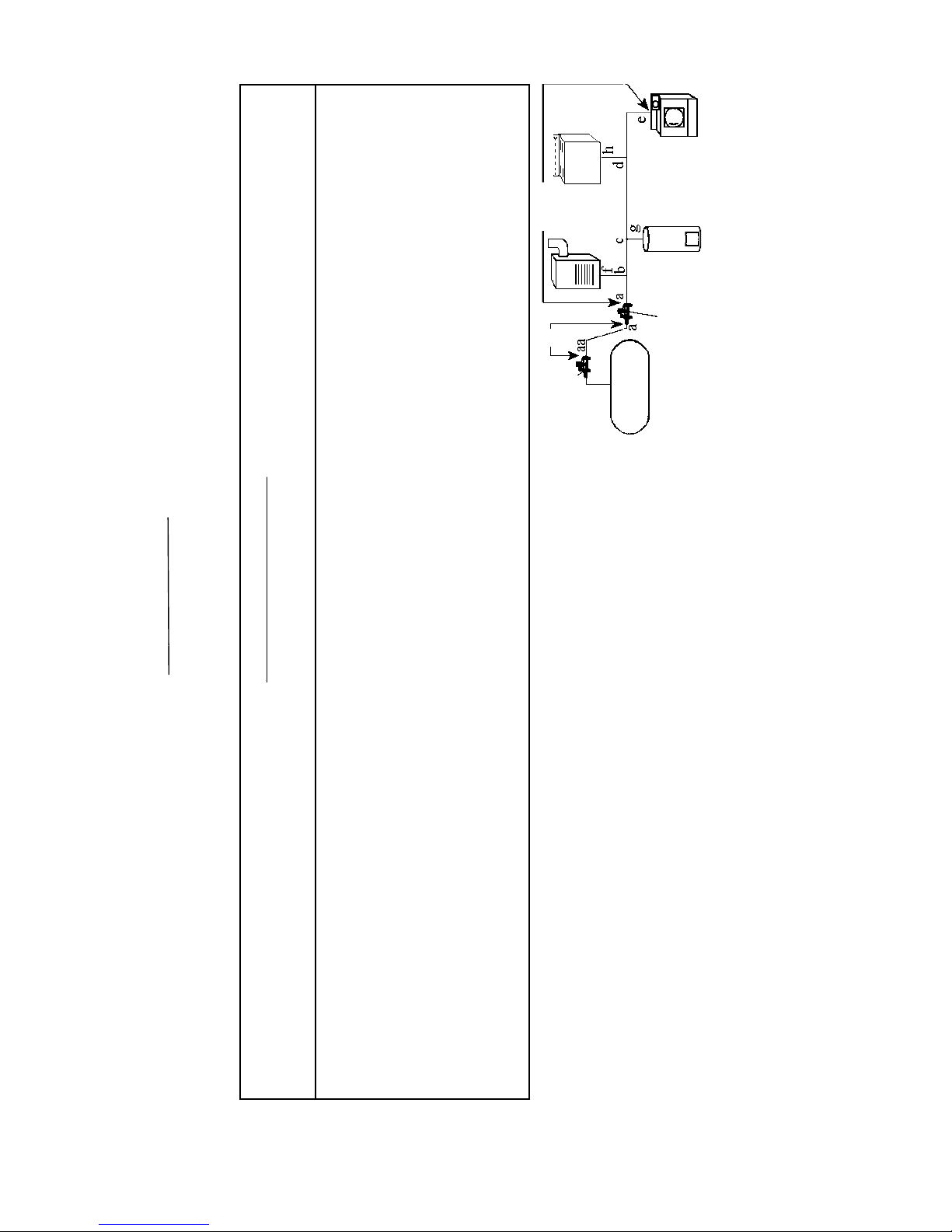
FRESHAIRFOR COMBUSTION,VENTILATION AND HEATDISTRIBUTION
With todays energy efficient homes, it is possible to make your home so air tight that it can result in stale air, dry rot, mold
development and host of other related problems. Gas burning appliances need fresh air for combustion as well as for
good distribution of heated air throughout the home. The following guide provides good general rules for classifying and
properly ventilating most homes.
“The National Fuel Gas Code ANSI Z223.1/NFPA54 defines a confined space as a space whose volume is less than 50
cubic feet per 1,000 Btu per hour (4.8m³ per Kw) of the aggregate input rating of all appliances installed in that space and
an unconfined space as a space whose volume is equal to or greater than 50 cubic feet per 1,000 Btu per hour (4.8m³ per
Kw) of the aggregate input rating of all appliances installed in that space. Rooms communicating directly with the space
in which the appliance is installed, through openings not furnished with doors, are considered a part of the unconfined
space.”
“This heater shall not be installed in a confined space or unusually tight construction unless provisions for adequate
combustion and ventilation air are made. Use the following example to determine if the heater is being installed in a
confined or unconfined space.”
STEP1. First find the cubic feet of area to be heated length x width x height. NOTE: Include any adjoining rooms that
cannot be separated by closing a door or that have a air exchange grille that cannot be closed between rooms.
EXAMPLE: Areasize25ft.x 15 ft. x 7-1/2 ft. =2,812.5cubicfeet.
STEP2. Divide area cubic feet by 50. EXAMPLE: 2,812.5 50 = 56.25. Multiply this number by 1,000 for total Btu input
roomcansupport.E XAMPLE: 56.25 x 1,000 = 56,250Btu.
STEP3. List all gas burning appliances in this area and total the combined Btu input. EXAMPLE:
Cozyvent freeheater…………………….. 20,000Btu
Gaswaterheater………………………….. 58,000 Btu
Gas range (all burners & oven on)……….. 28,000Btu
106,000Btu
Page 4

STEP4. Compare the total Btu the area can support (from Step 2) to the total Btu in the area the heater will be installed
(from Step 3). If the total from Step 2 is larger this is considered an unconfined space, if Btu total from Step 3 is larger this
is considered a confined space and provisions must be made for additional combustion and ventilation air. EXAMPLE:
Btu area can support is 56,250, total Btu in area is 106,000 – this would be a confined space.
NOTE: A third construction class is one with unusually tight construction, defined as, construction where: (A) Walls
and ceilings exposed to the outside atmosphere have a continuous water vapor retarder with a rating of 1 per (6x10-11 Kg
per pa-sec-m²) or less with openings gasketed or sealed, and, (B) Weatherstripping has been added on openable windows
and doors, and , (C) Caulking or sealants are applied to areas such as joints around window and door frames, between
sole plates and floors, between wall ceiling joints, between wall panels, at penetration for plumbing, electrical, and gas
lines, and at other openings.
“WARNING: If the area in which the heater may be operated is smaller than that defined as an unconfined space, or if the
building is of unusually tight construction, provide adequate combustion and ventilation air by one of the methods
described in the National Fuel Gas Code, ANSI Z223.1/NFPA54, Section 5.3 or applicable local codes.” Examples would
be to provide two permanent openings either to an adjoining room, or to the outside. See the National Fuel Gas Code for
details. See Figure 9 & Figure 10 below.
FRESH AIR FOR COMBUSTION, VENTILATION AND HEAT DISTRIBUTION - CONT’D.
INSTALLATION
Installationandservicemustbeperformedbyaqualifiedinstaller,serviceagencyorthegassupplier.
LOCATION
1) For most efficient performance, locate heater as centrally as possible in the area to be heated.
2) Do not install heater in a closet, alcove or small hallway where the heater could be isolated from the space to be
heated and adequate combustion air by closing a door.
Page 5
Chimney or gas vent
Opening
Opening
Equipment located in confined
spaces; all air from inside the
building. See5.3.3(a).
Furnace Water
Heater
FIGURE9
Chimney or gas vent
Water
Heater
Furnace
Ventilation louvers
(each end of attic)
Outlet Air
Inlet Air
Alternate
air inlet
Ventilation louvers for
unheated crawl space
Equipment located in confined spaces; all air from
outdoors - inlet air from ventilated crawl space and
outlet air to ventilated attic. See 5.3.3(b).
FIGURE10

3) Protect heater from wind, high traffic areas, and drafts (such as doorways, locations that get direct air from a ceiling
fan, etc.) as this will cause nuisance pilot outage.
4) Allmodelsmaybewall mounted. Model No. VFM10,VFT10,VFM20,VFT20,VFM30& VFT30 may befree
standing by adding optional VF-FSK floor stand kit. These floor mounted units must also have an approved, fire
resistant floor base (available from factory) and must be hard piped.
5) If optional blower is to be added, locate heater so there is safe access to an electrical outlet.
INSTALLATION - CONTINUED
1-5/8” 13-1/16”
FIGURE1
36”
8”
8”
3”
CLEARANCES
CLEARANCES
1) Maintain adequate accessibility clearances for
servicing and proper operation.
2) Minimum clearances as viewed from front of
heater. 3” clearance below heater shall be
measured from top surface of carpeting, tile,
etc.
3) If VF-FSK Free Standing Kit is used and the
heater is installed directly on carpeting, tile, or
other combustible material other than wood
flooring, the appliance shall be installed on a
metal or wood panel extending the full width
and depth of the appliance, such as a stove
board.
TOOLSANDADDITIONALSUPPLIES
REQUIRED
1) Pipe wrenches (2).
2) Phillip head screwdriver or screwgun.
3) Pressure test gauge.
4) An A.G.A. certified manual shut off valve
with 1/8” NPT pressure tap.
5) Union connector for type of piping used
(check local codes).
6) Pipe sealant certified for use with L.P. gas.
7) Components to assemble a drip leg.
8) Level.
9) Drill (if anchors are required).
ROUGH-INGASSUPPLY
1) Determine location of heater. (See
“Operation”, “Fresh Air”, and “Safety
Instructions” for details.
2) Install at least a ½” diameter gas supply line.
(Gas supply can enter through bottom or
back of heater). See Figure 1.
Page 6

Nominal
Iron Pipe Internal
Size, Diameter,
Inches Inches 10 20 30 40 50 60 70 80 90 100 125 150 175 200
¼ 0.364 43 29 24 20 18 16 15 14 13 12 11 10 9 8
3/8 0.493 95 65 52 45 40 36 33 31 29 27 24 22 20 19
½ 0.622 175 120 97 82 73 66 61 57 53 50 44 40 37 35
¾ 0.824 360 250 200 170 151 138 125 118 110 103 93 84 77 72
1 1.049 680 465 375 320 285 260 240 220 205 195 175 160 145 135
1-1/4 1.38 1400 950 770 660 580 530 490 460 430 400 360 325 300 280
1-1/2” 1.61 2100 1460 1180 990 900 810 750 690 650 620 550 500 460 430
2 2.067 3950 2750 2200 1900 1680 1520 1400 1300 1220 1150 1020 950 850 800
2-1/2 2.469 6300 4350 3520 3000 2650 2400 2250 2050 1950 1850 1650 1500 1370 1280
3 3.068 11000 7.7 6250 5300 4750 4300 3900 3700 3450 3250 2950 2650 2450 2280
4 4.026 23000 15800 12800 10900 9.7 8800 8100 7500 7200 6700 6000 5500 5000 4600
SEEFOLLOWINGCHARTSFROMNFPN54,ANSIZ223.1TODETERMINEPROPERGASSUPPLYLINESIZEREQUIREDTOSUPPORTTOTALBTUREQUIRE-
MENTS.
NATURAL GAS
Maximum Capacity of Pipe in Cubic Feet of Gas per Hour for Gas Pressures of 0.5 psig or Less and a Pressure Drop of 0.5 Inch Water Column.
(Basedon a 0.60 Specific Gravity Gas)
LENGTHOFPIPE,FEET
* Pipe and Tubing Selection
Total piping length = 84 feet (use table 4 @ 90 feet)
From a to b, demand =200,000 + 38,000 +65,000+35,000
= 338,000 BTU/hr. use 1” pipe.
From b to c, demand = 38,000 + 65,000 + 35,000
= 138,000 BTU/hr; use ¾” pipe or 7/8” tubing.
From c to d, demand = 65,000 + 35,000
= 100,000 BTU/hr; use ¾” pipe or ¾” tubing.
From d to e, demand = 35,000 BTU/hr; use ½” pipe or 5/8” tubing.
From b to f, demand = 200,000 BTU/hr; use 1” pipe.
From c to g, demand = 38,000 BTU/hr; use ½” pipe or 5/8” tubing.
From d to h, demand = 65,000 BTU/hr; use ½” pipe or ¾” tubing.
Example 2.
Determine the sizes of piping or tubing required for the two-stage L.P.
Gas installation shown.
First Stage
Regulator
26
Feet
Second Stage
Regulator
Water
Heater
38,000
Furnace
200,000
58
Feet Range
65,000
Clothes
Dryer
35,000
*Informationfrom -REGOPRODUCTS
“LPGASSERVICEMAN’SMANUAL”
SEEFOLLOWINGPAGEFORPIPESIZINGCHARTSFORPROPANEGAS.
Page 7
Total first stage piping length = 26 feet; first stage regulator setting is 10 PSIG (use Table 1 or 3,
@ 30 feet)
From aa to a, demand = 338,000 BTU/hr; use ½” pipe, ½”
tubing, or ½” T plastic pipe.
Total second stage piping length = 58 feet (use table 4, @
60 feet).
From a to b, demand = 338,000 BTU/hr; use 1” pipe.
From b to c, demand = 138,000 BTU/hr; use ¾” pipe or 7/8”
tubing.
From c to d, demand = 100,000 BTU/hr; use ½” pipe or ¾”
tubing.
From d to e, demand = 35,000 BTU/hr; use ½” pipe or ½”
tubing.
From b to f, demand = 200,000 BTU/hr; use ¾” pipe.
From c to g, demand = 38,000 BTU/hr; use ½” pipe or 5/8”
tubing.

TABLE 1 – first stage pipe sizing
10PSIGInlet with a 1 PSIG Pressure Drop
Maximum capacity of pipe or tubing, in thousands of BTU/hr. of L.P. Gas
Size of Pipe LENGTH OF PIPE OR TUBING, FEET*
Or Copper
Tubing, Inches 10 20 30 40 50 60 70 80 90 100
3/8 558 383 309 265 235 213 196 182 171 161
Copper ½ 1387 870 700 599 531 481 443 412 386 365
Tubing 5/8 2360 1622 1303 1115 988 896 824 767 719 679
(O.D.) ¾ 3993 2475 2205 1887 1672 1515 1394 1297 1217 1149
½ 3339 2295 1843 1577 1398 1267 1165 1084 1017 961
Pipe ¾ 6982 4799 3854 3298 2923 2649 2437 2267 2127 2009
Size 1 13153 9040 7259 6213 5507 4989 4590 4270 4007 3785
1-1/4 27004 18560 14904 12756 11306 10244 9424 8767 8226 7770
1-1/2 40461 27809 22331 19113 16939 15348 14120 13136 12325 11642
2 77924 53556 43008 36809 32623 29559 27194 25299 23737 22422
125 150 175 200 225 250 275 300 350 400
3/8 142 130 118 111 104 90 89 89 82 76
Copper ½ 323 293 269 251 235 222 211 201 185 172
Tubing 5/8 601 546 502 467 438 414 393 375 345 321
(O.D.) ¾ 1018 923 843 790 740 700 664 634 584 543
½ 852 772 710 660 619 585 556 530 488 454
Pipe ¾ 1780 1613 1484 1381 1296 1224 1162 1109 1020 949
Size 1 3354 3039 2796 2601 2441 2305 2190 2089 1922 1788
1-1/4 6887 6240 5741 5340 5011 4733 4495 4289 3945 3670
1-1/2 10318 9349 8601 8002 7508 7092 6735 6426 5911 5499
2 19871 18005 16564 15410 14459 13658 12971 12375 11385 10591
*Total length of piping from outlet of first stage regulator to inlet of second stage regulator (or to inlet of second stage regulator furthest
away).
Notes: 1) To allow 2 PSIG pressure drop, multiply total gas demand by .707, and use capacities from table.
2) For different first stage pressures, multiply total gas demand by the following factors, and use capacities from table.
First State Pressure PSIG Multiply by
20 .844
21 .912 Data Calculated per NFPA #54 & 58.
TABLE 4 – Second, Single, or Integral Twin Stage Pipe Sizing
11 Inches Water Column Inlet with a ½ Inch Water Column Drop
Maximum capacity of pipe or tubing in thousands of BTU/hr of LP-Gas
Size of Pipe LENGTH OF PIPE OR TUBING, FEET*
Or Copper
Tubing, Inches 10 20 30 40 50 60 70 80 90 100
3/8493427232019————
Copper 1/2 110 76 61 52 46 42 38 36 33 32
Tubing 5/8 206 141 114 97 86 78 71 67 62 59
(O.D.) 3/4 348 239 192 164 146 132 120 113 105 100
7/8 536 368 296 253 224 203 185 174 161 154
1/2 291 200 161 137 122 110 102 94 87 84
Pipe 3/4 608 418 336 287 255 231 212 198 185 175
Size 1 1146 788 632 541 480 435 400 372 349 330
1-1/4 2353 1617 1299 1111 985 892 821 764 717 677
1-1/2 3525 2423 1946 1665 1476 1337 1230 1144 1074 1014
2 6789 4666 3747 3207 2842 2575 2369 2204 2068 1954
125 150 175 200 225 250 275 300 350 400
3/8——————————
Copper 1/2 ——————————
Tubing 5/8 ——————————
(O.D.) 3/4 ——————————
7/8——————————
1/2 74 67 62 58 54 51 48 46 43 40
Pipe 3/4 155 141 129 120 113 107 101 97 89 83
Size 1 292 265 244 227 213 201 191 182 167 156
1-1/4 600 544 500 465 437 412 392 374 344 320
1-1/2 899 815 749 697 654 618 587 560 515 479
2 1731 1569 1443 1343 1260 1190 1130 1078 992 923
*Total length of piping from outlet of regulator to appliance furthest away. Data Calculated per NFPA #54 & 58.
Page 8
PROPANE GAS
PROPANE GAS

INSTALLINGHEATER
WALLMOUNT (VFM6,VFM10,VFT10)
STEP1.Removewallmountingbracket from back of
heater.
STEP2. Locate wall stud.
STEP3. Attach wall mounting bracket to wall stud
with top at desired height, using (2) screws provided.
Make sure top of bracket is level. See Figure 2.
STEP4. Hang top of heater on wall mounting bracket.
STEP5. Remove bottom front panel.
STEP6. Secure back of heater to wall, utilizing
anchors (if necessary) or wood screws. See Figure 3.
WALLMOUNT
(VFM20,VFT20,VFM30,VFT30)
STEP1. Removewallmountingbracket from back of
heater.
STEP2. Locate two studs.
STEP3. Attach wall mounting bracket to wall studs with
top at desired height using (2) wood screws provided.
Make sure top of bracket is level. See Figure 4.
STEP4. Hang top of heater over wall mounting bracket.
STEP5. Remove bottom front panel.
STEP6. Secure back of heater to wall, utilizing anchors (if
necessary) or wood screws. See Figure 3.
Wall Mounting Bracket Wall Stud
FIGURE4
HOLESFORMOUNTINGBACKOF
HEATER TOWALL
FIGURE3
Page 9
HEATER
Make sure this cut-out
faces back of heater.
INSTALLINGVF-FSKFLOORBASEKIT
STEP1. Remove floor base from carton.
STEP2. Align screw holes in base to holes in heater
bottom.
STEP3. Make sure that cut-out in top of floor base aligns
with cut-out in bottom of heater and the other cut-out in
bottom of heater and the other cut-out in base if facing
towards back of unit (see illustration below).
STEP4. Attach floor base to bottom of heater using four
#8 screws (provided).
NOTE: Floorbases are for use on VFM10, VFT10,VFM-
20,VFT-20, VFM30andVFT30only. TheVFM6Serieshas
no base and is not approved for use with one.
WALLSTUD
WALL
MOUNTING
BRACKET
FIGURE2

GASCONNECTION
STEP 1. Makethegasconnection betweenthemanual shutoffvalveand regulatorlocatedinside
heatercabinet. Hold regulatorwhentightening connectiontoprevent damagetoregulator
andinternal tubing. SeeFigure5forcompleted installation.
NOTE: All piping andconnection mustbecheckedfor leaks bytheinstaller. If connectionsarenot
exposed,apressure testmustberun. The applianceanditsindividual shut offvalvemust
bedisconnectedfromthegassupply pipingsystemduringany pressuretestingat pressures
inexcessof½ psig (3.5 kPa). The appliancemustbeisolatedfrom the gas supply piping
systembyclosingitsindividualmanualshutoffvalveduringanypressuretestingofthegas
supplypipingsystemattestpressuresequal to or less than ½ psig (3.5kPa).
Internal Regulator
(Supplied)
Union
DripLeg
Manual Shut Off
Outside Reg.
Supplied
by Gas Co.
1/8”NPTPlug
FIGURE5
Manual
Cut off
Valve
1/8” NPT
Pressure
Plug Drip
Leg
GASPIPINGWITHVF-FSKKIT
FIGURE5A
Page 10

A. This appliance has a pilot which must be lighted by
hand. When lighting the pilot, follow these
instructions exactly.
B. BEFORE LIGHTING smellallaroundthe appliance
area for gas. Be sure to smell next to the floor
because some gas is heavier than air and will settle
on the floor.
WHAT TODO IFYOUSMELLGAS:
•Do not try to light any appliance.
•Do not touch any electric switch, do not use any
phone in your building.
•Immediately call your gas supplier from a
neighbor’s phone. Follow the gas supplier’s
instructions.
VFM63, VFM103 - NATURAL GAS VFM64, VFM104 - L.P. GAS
FOR YOUR SAFETY READ BEFORE LIGHT
WARNING: IFYOUDONOTFOLLOWTHESEINSTRUCTIONSEXACTLY,A
FIREOREXPLOSIONMAYRESULTCAUSINGPROPERTYDAMAGE,
PERSONALINJURY ORLOSSOFLIFE.
•If you cannot reach your gas supplier, call the fire
department.
C. Use only your hand to push in or turn the gas control
knob. Never use tools. If the knob will not push in or
turn by hand, don’t try to repair it, call a qualified
service technician. Force or attempted repair may
result in a fire or explosion.
D. Do not use this appliance if any part has been under
water. Immediately call a qualified service technician
to inspect the appliance and to replace any part of the
control system and any gas control which has been
under water.
LIGHTING INSTRUCTIONS
1. STOP! Read the safety information above on this
label.
2. Depress gas control knob slightly and turn
clockwise to “OFF”.
4. Wait five (5) minutes to clear out any gas. Then smell
for gas, including near the floor. If you smell gas,
STOP! Follow“B” in the safety information above
on this label. If you don’t smell gas, go to the next
step.
5. Locate pilot in the cut-out below the burner.
6. Locate piezo ignitor button on top of heater.
7. Turn gas control knob counterclockwise to
“PILOT”.
8. Depress gas control knob and hold in. Immediately
begin alternately pushing and releasing piezo
ignitor button, observing pilot, until pilot is lit.
Continue to hold the control knob in for about one
(1) minute after the pilot is lit. Release the gas
control knob and it will pop back up. Pilot should
remain lit. If pilot goes out, repeat steps 2 thru 7.
•If knob does not pop up when released, STOP and
immediately call your service technician or gas
supplier.
•If the pilot will not stay lit after several tries, turn the
gas control knob to “OFF” and call your service
technician or gas supplier.
9. Turn gas control knob counterclockwise to
“ON”.
TO TURN OFF GAS TO APPLIANCE
1. Depress gas control knob slightly and turn clockwise to “OFF”.
Gas
Control
Knob
NOTE: Knob can not be turned from “PILOT” to
“OFF” unless knob is depressed slightly. Do not force.
Page11
3. Turn off all electric power to the appliance.

VFM203 - NATURAL GAS VFM204 - L.P. GAS
FOR YOUR SAFETY READ BEFORE LIGHTING
WARNING: IFYOUDONOTFOLLOWTHESEINSTRUCTIONSEXACTLY,A
FIREOREXPLOSIONMAYRESULT CAUSINGPROPERTY DAMAGE, PER-
SONALINJURYOR LOSS OFLIFE.
A. This appliance has a pilot which must be lighted by
hand. When lighting the pilot, follow these instruc-
tions exactly.
B. BEFORE LIGHTING smellallaroundthe appliance
area for gas. Be sure to smell next to the floor
because some gas is heavier than air and will settle
on the floor.
WHAT TODO IFYOUSMELLGAS:
•Do not try to light any appliance.
•Do not touch any electric switch, do not use any
phone in your building.
•Immediately call your gas supplier from a
neighbor’s phone. Follow the gas supplier’s
instructions.
•If you cannot reach your gas supplier, call the
fire department.
C. Use only your hand to push in or turn the gas
control knob. Never use tools. If the knob will not
push in or turn by hand, don’t try to repair it, call a
qualified service technician. Force or attempted
repair may result in a fire or explosion.
D. Do not use this appliance if any part has been
under water. Immediately call a qualified service
technician to inspect the appliance and to replace
any part of the control system and any gas control
which has been under water.
LIGHTING INSTRUCTIONS
1. STOP! Read the safety information above on this
label.
2. Depress gas control knob slightly and turn clockwise
to “OFF”.
3. Turn off all electric power to the appliance.
4. Wait five (5) minutes to clear out any gas. Then smell
for gas, including near the floor. If you smell gas,
STOP! Follow “B” in the safety information above
on this label. If you don’t smell gas, go to the next
step.
5. Locate pilot in the cut-out below the burner.
6. Locate piezo ignitor button on top of heater.
7. Turn gas control knob counterclockwise to
“PILOT”.
8. Depress gas control knob and hold in. Immediately
begin alternately pushing and releasing piezo
ignitor button, observing pilot, until pilot is lit.
Continue to hold the control knob in for about
one (1) minute after the pilot is lit. Release the
gas control knob and it will pop back up. Pilot
should remain lit. If pilot goes out, repeat steps
2 thru 7.
•If knob does not pop up when released, STOP and
immediately call your service technician or gas
supplier.
•If the pilot will not stay lit after several tries, turn
the gas control knob to “OFF” and call your
service technician or gas supplier.
9. Turn on all electric power to the appliance.
10. Turn gas control knob counterclockwise to
desired “LO” or “HI” setting.
TO TURN OFF GAS TO APPLIANCE
1. Depress gas control knob slightly and turn clockwise to “OFF”.
2. Turn off all electric power to the appliance if service is to be performed.
Gas
Control
Knob
NOTE: Knob can not be turned from “PILOT” to “OFF” unless
knob is depressed slightly. Do not force.
Page 12

VFM303 - NATURAL GAS VFM304 - L.P. GAS
FOR YOUR SAFETY READ BEFORE LIGHTING
A. This appliance has a pilot which must be lighted by
hand. When lighting the pilot, follow these instruc-
tions exactly.
B. BEFORE LIGHTING smellallaroundthe appliance
area for gas. Be sure to smell next to the floor
because some gas is heavier than air and will settle
on the floor.
WHAT TODO IFYOUSMELLGAS:
•Do not try to light any appliance.
•Do not touch any electric switch, do not use any
phone in your building.
•Immediately call your gas supplier from a
neighbor’s phone. Follow the gas supplier’s
instructions.
•If you cannot reach your gas supplier, call the fire
department.
C. Use only your hand to push in or turn the gas control
knob. Never use tools. If the knob will not push in or
turn by hand, don’t try to repair it, call a qualified
service technician. Force or attempted repair may
result in a fire or explosion.
D. Do not use this appliance if any part has been under
water. Immediately call a qualified service technician
to inspect the appliance and to replace any part of the
control system and any gas control which has been
under water.
WARNING: IFYOUDONOTFOLLOWTHESEINSTRUCTIONS EXACTLY,AFIREOR
EXPLOSIONMAY RESULTCAUSINGPROPERTYDAMAGE,PERSONALINJURYOR
LOSSOFLIFE.
LIGHTING INSTRUCTIONS
1. STOP! Read the safety information above on this
label.
2. Depress gas control knob slightly and turn
clockwise to “OFF”.
3. Turn off all electric power to the appliance.
Gas
Control
Knob
NOTE: Knob can not be turned from “PILOT” to “OFF”
unless knob is depressed slightly. Do not force.
4. Wait five (5) minutes to clear out any gas. Then
smellforgas,including near the floor. If you smell
gas, STOP! Follow “B” in the safety information
above on this label. If you don’t smell gas, go to
the next step.
5. Locate pilot in the cut-out below the burner.
6. Locate piezo ignitor button on top of heater.
7. Turn gas control knob counterclockwise to
“PILOT”.
8. Depress gas control knob and hold in. Immediately
begin alternately pushing and releasing piezo
ignitor button, observing pilot, until pilot is lit.
Continue to hold the control knob in for about one
(1) minute after the pilot is lit. Release the gas
control knob and it will pop back up. Pilot should
remain lit. If pilot goes out, repeat steps 2 thru 7.
•If knob does not pop up when released, STOP and
immediately call your service technician or gas
supplier.
•If the pilot will not stay lit after several tries, turn the
gas control knob to “OFF” and call your service
technician or gas supplier.
9. Turn on all electric power to the appliance.
10. Turn gas control knob counterclockwise to
desired temperature setting.
1. Depress gas control knob slightly and turn clockwise to “OFF”.
2. Turn off all electric power to the appliance if service is to be performed.
TO TURN OFF GAS TO APPLIANCE
Page 13

VFT101, VFT201, VFT301 - NAT. GAS /VFT102, VFT202, VFT302 - L.P.
GAS
FOR YOUR SAFETY READ BEFORE LIGHTING
WARNING: IFYOUDONOTFOLLOWTHESEINSTRUCTIONSEXACTLY,A
FIREOREXPLOSIONMAYRESULTCAUSING PROPERTYDAMAGE, PER-
SONALINJURY ORLOSSOFLIFE.
A. This appliance has a pilot which must be lighted by
hand. When lighting the pilot, follow these instruc-
tions exactly.
B. BEFORE LIGHTING smellallaroundthe appliance
area for gas. Be sure to smell next to the floor
because some gas is heavier than air and will settle
on the floor.
WHAT TODO IFYOUSMELLGAS:
•Do not try to light any appliance.
•Do not touch any electric switch, do not use any
phone in your building.
•Immediately call your gas supplier from a
neighbor’s phone. Follow the gas supplier’s
instructions.
•If you cannot reach your gas supplier, call the
fire department.
C. Use only your hand to push in or turn the gas
control knob. Never use tools. If the knob will
not push in or turn by hand, don’t try to repair it,
call a qualified service technician. Force or
attempted repair may result in a fire or explosion.
D. Do not use this appliance if any part has been
under water. Immediately call a qualified service
technician to inspect the appliance and to replace
any part of the control system and any gas
control which has been under water.
LIGHTING INSTRUCTIONS
1. STOP! Read the safety information above on this
label.
2. Depress gas control knob slightly and turn clockwise
to “OFF”.
3. Turn off all electric power to the appliance.
4. Wait five (5) minutes to clear out any gas. Then smell
for gas, including near the floor. If you smell gas,
STOP! Follow “B” in the safety information above
on this label. If you don’t smell gas, go to the next
step.
5. Locate pilot in the cut-out below the burner.
6. Locate piezo ignitor button on top of heater.
7. Turn gas control knob counterclockwise to
“PILOT”.
8. Depress gas control knob and hold in.
Immediately begin alternately pushing and
releasing piezo ignitor button, observing pilot,
until pilot is lit. Continue to hold the control
knob in for about one (1) minute after the pilot
is lit. Release the gas control knob and it will
pop back up. Pilot should remain lit. If pilot
goes out, repeat steps 2 thru 7.
•If knob does not pop up when released, STOP
and immediately call your service technician or
gas supplier.
•If the pilot will not stay lit after several tries, turn
the gas control knob to “OFF” and call your
service technician or gas supplier.
9. Turn on all electric power to the appliance.
10. Turn gas control knob counterclockwise to
desired temperature setting.
TO TURN OFF GAS TO APPLIANCE
1. Depress gas control knob slightly and turn clockwise to “OFF”.
2. Turn off all electric power to the appliance if service is to be performed.
Gas
Control
Knob
NOTE: Knob can not be turned from “PILOT” to “OFF” unless
knob is depressed slightly. Do not force.
Page 14

PROPEROPERATION
ODS/PILOTFLAME
Thepilotpressurehasbeenpre-set at the factory and with proper supply pressure willprovideasafe,
reliableignition source. SeeFigure6.
CORRECT INCORRECT-
LOWPRESSURE INCORRECT-OXYGEN
LEVELDROPPING
BURNERFLAME
All orificing and pressure setting was done at the factory and, with proper supply pressure, will provide a safe, efficient
source of heat. However, if any questions about manifold pressure, have a qualified serviceman check with a manometer,
Natural Gas will be 5”, L.P. Gas will be 10” w.c. A proper burner flame (See Figure 7) will produce a reddish-orange flow on
the surface of the ceramic burner plaques. If the burner flame has blue streamers or the flame is floating off the surface of
the plaques, turn heater off and call a qualified service person. Do not operate heater if all plaques are not glowing.
NOTE: There will be approximately ¼” space on the sides and top of the burner that will not glow.
VFM20: When turned to the “LO” setting the two middle plaques will light and glow. When valve is turned to “HI” then
all four plaques will be lit.
CORRECTFLAME INCORRECTFLAME
FIGURE7
Page 15
VFM20/ CORRECT FLAME
“LO” VFM20/ CORRECT FLAME
“HI”

ApplyAir
STEP 3 - PILOT CLEANING
MAINTENANCE
Theentireheatershouldbechecked and cleaned by a qualified service personbeforethestartofeach
heatingseason. More frequentcleaningmayberequireddueto excessivelintconditions fromcarpeting,
beddingmaterial,etc.
CABINET
To cleanthecabinetandhearth and jamb assembliesofyourheater, turnoffand allowtocool,thenwipe
withasoft dampcloth. Thiswillremoveany dust. Neverusemetalpolish, furniture wax,oranytype of
cleaningsolutionas this couldcauseodorswhenthe heater is turnedbackon.
MAIN BURNER
Burnersmaybecleanedbyusingalowpressure airhose,orsoftbrush. Becarefulnottodamagethe
ceramicplaque.
ODS/PILOT
STEP1. Removebottomfront panel.
STEP2. Disconnectpilotlinefrompilot.
STEP3. Use alowpressureairhose to blow throughpilotandthroughODS opening insideofpilot.
WARNING: Neverinsertanythingintoany oftheopenings inthepilotas thiscoulddamage theOxygen
DepletionSystemand exposethehomeownerto CarbonMonoxidepoisoning.
WARNING: After anyservicingorcleaning make sureheateriscompletely re-assembledandcheckfor
gasleaks.
Page 16

BLOWERINSTRUCTIONS
INSTALLINGTHEVFBBLOWER
STEP1. Remove blower assembly from shipping carton.
STEP2. Insert blower assembly into upper back of heater (See Figure 8).
STEP3. Secure blower to heater using three #8 screws (provided) through holes pre-punched in heater back.
STEP4. Locate mounting holes for switchbox (See Figure 8).
STEP5. Secure switchbox to heater using two #8 screws (provided).
STEP6. Plug power cord into 115 volt three-prong grounded receptacle.
CAUTION: Always unplug power cord before servicing or cleaning heater. This appliance is equipped with a three-
prong (grounding) plug for your protection against shock hazard and should be plugged directly into a
properly grounded three-prong receptacle.
Label all wires prior to disconnection when servicing controls. Wiring errors can cause improper
and dangerous operation. Verify proper operation after servicing.
FIGURE8
Switchbox
Blower Assembly
Blower
Motor
Black
White
Fan
Switch
White
(or ribbed)
Green
Black
WIRINGDIAGRAM/VFBBLOWER
Page 17
Ifanyoftheoriginalwiresupplied
with the appliance must be re-
placed,itmustbereplacedwitha
wireofat least a 105/Ctempera-
turerating.

XXXXXXX
XXXXXXX
XXXXXXX
XXXXXXX
XXXXXXX
XXXXXXX
33
32
30
31 7
18
20
11 12
16
10 13
17
19
21
24
22 5
14
2
15
26 25
1
9
3
6
23
MANUALMODELS
NAT. GAS L.P. GAS
VFM63 VFM64
VFM103 VFM104
VFM203 VFM204
VFM303 VFM304
VENTFREE INFRA-REDHEATER
MANUALCONTROL
PARTSLIST
Pricesandspecifications subjecttochange
withoutnotice. Allpricesare F.O.B.factory.
Blower
Parts
Page 18
VFM63,
VFM64
3
VFM103,
VFM104 3 a, b
“LO”
“HI”
VFM203, VFM204
“HI”
“MED.”
“LO”
3 a, b, c
VFM303, VFM304

MODEL NUMBERS NATURAL VFM63 VFM103 VFM203 VFM303
MODEL NUMBERS PROPANE VFM64 VFM104 VFM204 VFM304
REF. PART LIST PART LIST PART LIST PART LIST
PART DESCRIPTION NO. NO. PRICE NO. PRICE NO. PRICE NO. PRICE
Valve, CPMM-21400/17 1 88290 $40.60 88290 $40.60 88291 $42.00 88177 $41.30
ODS/Pilot (NAT. GAS) 2 88169 $41.90 88169 $41.90 88169 $41.90 88169 $41.90
ODS/Pilot (L.P. GAS) 2 88168 $36.20 88168 $36.20 88168 $36.20 88168 $36.20
Manifold 3 88147 $10.10 88148 $20.10 N/A N/A N/A N/A
Manifold “LO” 3a N/A N/A N/A N/A 88155 $18.40 88157 $18.80
Manifold “HI” 3b N/A N/A N/A N/A 88156 $17.90 88159 $18.80
Manifold “MEDIUM” 3c N/A N/A N/A N/A N/A N/A 88158 $18.80
Burner Orifice (NAT. GAS) 5 88021 $3.40 88021 $3.40 88021 $3.40 88021 $3.40
Burner Orifice (L.P. GAS) 5 88020 $3.40 88020 $3.40 88020 $3.40 88020 $3.40
Gas Regulator (NAT. GAS) 6 88035 $17.50 88035 $17.50 88031 $17.50 88031 $17.50
Gas Regulator (L.P. GAS) 6 88036 $17.50 88036 $17.50 88032 $17.50 88032 $17.50
Burner Assembly 7 88150 $42.20 88151 $79.70 88152 $145.50 88153 $197.40
Gas Supply Tube 9 88045 $2.80 88066 $4.20 88066 $4.20 88049 $4.70
Control Rod 10 88019 $11.70 88019 $11.70 88019 $11.70 88019 $11.70
Control Knob 11 88075 $4.00 88075 $4.00 88008 $5.90 88010 $6.60
Wall Mounting Bracket 12 35220 $7.00 35220 $7.00 35960 $8.60 35960 $8.60
Piezo 13 80016 $5.70 80016 $5.70 80016 $5.70 80016 $5.70
Electrode Wire 30" 14 88070 $2.80 88070 $2.80 88070 $2.80 88070 $2.80
Pilot Tubing Assy.24"Nat.&L.P. 15 88013 $4.70 88013 $4.70 88013 $4.70 88013 $4.70
Control Rod Grommet 16 88018 $1.10 88018 $1.10 88018 $1.10 88018 $1.10
Casing Back 17 35165 $16.90 35425 $19.30 35925 $20.00 36425 $25.90
Casing Left Side 18 35060 $13.10 35060 $13.10 35060 $13.10 35060 $13.10
Casing Right Side 19 35070 $13.10 35070 $13.10 35070 $13.10 35070 $13.10
Top Front Panel 20 35045 $14.90 35340 $16.20 35870 $12.70 36340 $21.20
Bottom Front Panel 21 35080 $10.10 35360 $10.70 35860 $12.40 36360 $13.80
Bezel Assembly 22 35100 $43.40 35380 $46.80 35880 $51.70 36380 $58.30
Wire Guard 23 88100 $21.40 88101 $23.00 88105 $26.60 88104 $33.40
Heat Shield 24 35200 $2.60 35460 $2.90 35940 $4.00 36440 $4.60
Valve Support Bracket 25 35185 $2.90 N/A N/A 35185 $2.90 35185 $2.90
Regulator Support Bracket 26 35240 $5.00 35480 $4.00 35240 $5.00 35480 $4.00
Lighting Instruction Assembly 91370 $2.80 91370 $2.80 91371 $2.80 91380 $4.50
BLOWER PARTS VF-B
Blower/Motor Assembly 30 N/A N/A 88250 $58.60 88250 $58.60
Blower Housing 31 N/A N/A 37025 $13.00 37025 $13.00
Fan Switch 32 N/A N/A 88240 $5.90 88240 $5.90
Power Cord 33 N/A N/A 80202 $4.20 80202 $4.20
Junction Box N/A N/A 37075 $6.10 37075 $6.10
Junction Box Cover N/A N/A 37085 $7.80 37085 $7.80
* TWO REQUIRED
REPLACEMENTPARTSLIST.TOORDERREPLACEMENTPARTSYOUMUSTGIVEMODELNUMBER,SERIAL
NUMBER,TYPEOFGASUSED,PARTDESCRIPTIONANDPARTNUMBER.
MARCH 2005
Page 19
Mr. Contractor, we only sell parts through our wholesalers, but the prices listed above are for your convenience.
For prompt parts service, contact the wholesaler from which you purchased your Cozy heater. NOTE: Parts &
schematic drawings on current models are shown at www.cozyheaters.com.

THERMOSTATMODELS
NAT. GAS L.P. GAS
VFT101 VFT102
VFT201 VFT202
VFT302 VFT302
VENTFREE INFRA-REDHEATER
THERMOSTATCONTROL
PARTSLIST
Pricesandspecifications subjecttochange
withoutnotice. Allpricesare F.O.B. factory.
12
16
13
17
19
21
2
15
26
14
1
9
6
5
22
23
24
7
18
33
20
31
30
32
Page 20
3VFT101,VFT102
VFT201, VFT202
VFT301, VFT302
Blower
Parts
XXXXXXX
XXXXXXX
XXXXXXX
XXXXXXX
XXXXXXX
XXXXXXX
Mr.Contractor, we only sell parts through
our wholesalers, but the prices listed are for
your convenience. For prompt parts
service, contact the wholesaler from which
you purchased your Cozy heater. NOTE:
Parts & schematic drawings on current
modelsareshownatwww.cozyheaters.com.
This manual suits for next models
13
Table of contents
Other COZY Heater manuals
Popular Heater manuals by other brands

MO-EL
MO-EL GUADALUPA Use and maintenance

Coates
Coates ST Series Installation & operation manual

Taurus
Taurus Cairo Slim 650 Manual information

Rointe
Rointe ecodesign BELIZE SHORT Installation and user manual

Kogan
Kogan KGNPHT22VA user manual

AEG Haustechnik
AEG Haustechnik EWH Comfort Series Operating and installation instructions