SMITH SYSTEM LS 541N Quick start guide

LS 541N
SMITH SYSTEM
ASSEMBLY INSTRUCTIONS /OWNERS MANUAL
IMPORTANT:READALLASSEMBLYINSTRUCTIONSAND SAFETYPRECAUTIONSBEFOREUSINGTHISPRODUCT.
REFERENCEALL SAFETYGUIDELINESAND WARNING LABELS.RETAINPRODUCTLITERATUREFOR
FUTUREREFERENCE.
SAFETY:P ROPERLYWARMUPANDSTRETCHBEFOREEXERCISING.IFYOUFEELPAINORDIZZINESSATANY
TIMEWHILEEXERCISING,STOPIMMEDIATELYAND CONSULTYOUR PHYSICIAN.
POB-2012-04 RevB
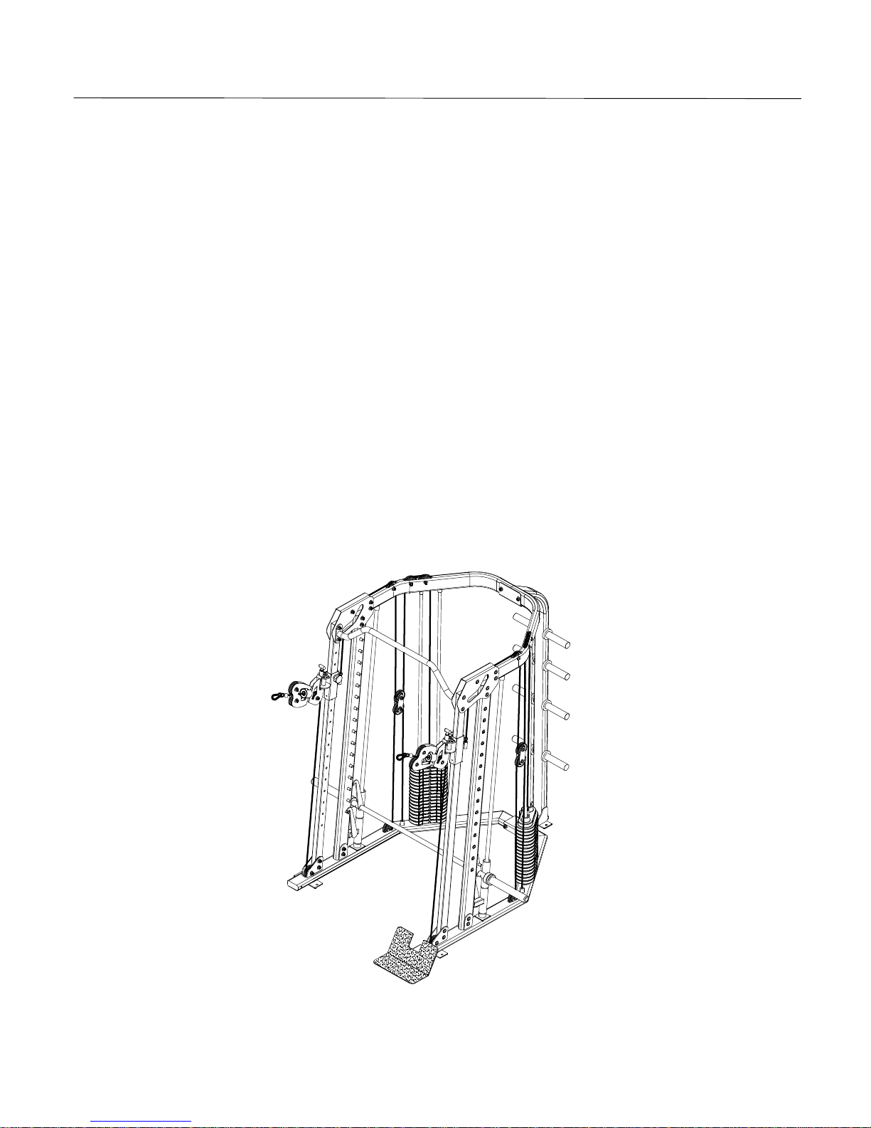
** Show with optional LS 513N DFI Bench

Tableof Contents
ReferencePage
HardwareCharts2
PartsListing 3-4
Product Exploded View5
AssemblyPrep 6
AssemblyInstructions7-10
PulleyAssembly11
CableRouting 12
PreventativeMaintenance13
Important Precautions
Warning:Toreducethe riskofinjury,pleaseread the following precautionsbeforeassembling orusing yournewproduct.
1. Itistheresponsibilityoftheownertoensurethatallusersof thisequipmentareadequatelyinformedof statedprecautions.
2. Readallinstructionsandenclosedliteraturecarefully. Understandtheassemblystagesandfunctionof theequipmentbeforeuse.
3. Useequipmentonaflatlevelsurface.
4. Itisrecommendedtoplace anexercise/productmustbeneaththeequipmentforaddedprotectionof floorsorcarpets.
5. Keepchildren&petsawayfromequipmentatalltimes.
6. Inspectproduct onafrequentbasis.Tightenlooseassembliesorhardwareasneeded. Replace wornordamagedparts.
7. Thisequipmentisintendedforinternalhomeuseonly. Donotuseinanon-residentialenvironment.Useinnon-recommended
environmentscanleadtoseriousinjuryandwillvoidallrelatedwarranties&liabilities.
8. Recommendeduserloadshouldnotexceed500lbs. (including userbodyweight&plate/barload).
9. Frequentlywipetheequipmentdownwithadampenedsoftcloth.
10. Observeand adheretoallwarninglabelspostedontheequipment.
11. Properlywarmupand stretchbeforestartinganystrengthtrainingorcardioexerciseroutine.
12. Ifyoufeelpainordizziness atanytimewhileexercising, stopimmediatelyandconsultyourphysician.
Safety Warning:Beforestartinganexerciseprogram, consult yourphysician.Thisisespeciallyimportantforindividualsoverthe
ageof 35 orpersonswithpre-existinghealthproblems. Itisimportanttoreadallinstructionscarefully.Weassumenoresponsibility
forpersonalinjuryorconsequentialdamagessustainedbyorthroughtheuseof thisequipment.Additionaltermsandconditionsare
listedinthebackof thismanualorenclosedownersmanual.
Page 1
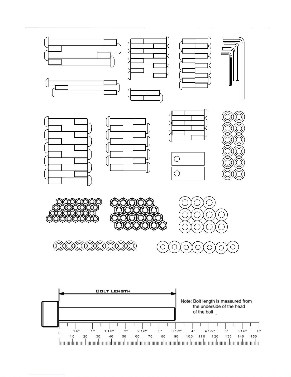
HARDWARE CHART ASSEMBLY HARDWARE
Page 2
ButtonHeadAllenScrew
1/2"-13UNC
3"L (10PCS)
ButtonHeadAllenScrew
1/2
"-
13
UNC
23/4
"L (8PCS)
(2PCS)
Clevis25.4
63.5L (12PCS)
StepSpacer16.2
10.1
9H
ButtonHeadAllenScrew
3/8"-16UNC
23/4"L
ButtonHeadAllenScrew
3/8"-16UNC
21/4"L
ButtonHeadAllenScrew
3/8
"-1
6
UNC
43/4
"L
ButtonHeadAllenScrew
1/2"-13UNC
43/4"L
ButtonHeadAllenScrew
3/8
"-1
6
UNC
51/4
"L
(1PC) (2PCS)
ButtonHeadAllenScrew
1/2"-13UNC
51/4"L (2PCS)
(
2
PCS)
(2PCS)
(8PCS)
ButtonHeadAllenScrew
3/8"-16UNC
2"L
ButtonHeadAllenScrew
3/8"-16UNC
21/2"L
(10PCS)
(6PCS)
(1PC)
(1PC)
AllenWrenchM6
(1PC)
AllenWrenchM
8
AllenWrenchM5
(1PC)
AllenWrenchM4
NylonNut3/8"-16UNC 11t
Step Spacer16.2 10.1 12.5H
(29PCS)
(4PCS) Step Spacer16.2 10.1 14H
(4PCS)
(22PCS)
NylonNut
1/2"-13UNC 12t FlatWasher
26 13 2.0t
(38PCS)
FlatWasher
25 10 2.0t
(44PCS)
Note: Hardware and assembly tools are not shown at actual size. Certain assembly hardware may not be referenced
in the chart above. For easier assembly some hardware may be preinstalled in the assembly locations of the product.
Please reference the itemized parts listing and individual assembly steps for additional hardware information.

PARTS REFERENCE
ASSEMBLY PARTS
Page 3
53
54
55
56
57
17
17
12
13
19
20
21
22
22
21
23
10
44
1825
26
45
48
47
4
14
3
1
2
5
6
7
8
9
44
10
11
46
46
15
15
16
16
27
27
46
46

Item#Part # Description Qty.
1 P20-3526 Base(Left) 1
2 P20-3527 Base(Right) 1
3 P20-3681 RearUpright1
4 P20-3531 VerticalTube Adjustable(Left) 1
5 P20-3530 VerticalTube Adjustable(Right) 1
6 P20-3529 OlympicBarSupport (Right) 1
7 P20-3528 OlympicBarSupport (Left) 1
8 P20-3534 HandleBarAdjustable(Left) 1
9 P20-3535 HandleBarAdjustable(Right) 1
10 P20-1534 OlympicBarAdjustable 2
11 P20-3684 OlympicBarAdjustable(Left) 1
12 P20-3682 Top Brace(Left) 1
13 P20-3686 Top Brace(Right) 1
14 P04-0616 Top Bar 1
15 P20-3676 Swiveling Pulley Handles Assembly 2
16 P11-0209 T Handle Pop Pin 2
17 P02-0753 Top Beam 2
18 P20-1536 Foot Plate 1
19 P02-0852 LBracket , Top 1
20 P02-0849 LBracket , Botton 1
21 P01-0868 GuideRod 19x1925L 4
22 P01-0869 LinerShaft 25x1881L 2
23 P20-3685 OlympicBarAdjustable(Right) 1
24 P03-0406 Shaft 16 x65L 32
25 P04-0794 OlympicBar 1
26 P03-0405 OlympicBarShaft 1
27 P02-0734 PulleyBracket 4
28 P20-1543 Top Weight +SelectorStem 2
29 P03-0284 Clevis25.4x63.5L 2
30 DAEE01251413NU Button Head Allen Screw1/2 -13uncx5 1/4"L 2
31 DAEE01243413NU Button Head Allen Screw1/2 -13uncx4 3/4"L 2
32 DAEE01230013NU Button Head Allen Screw1/2 -13uncx3 L 10
33 DAEE01223413NU Button Head Allen Screw1/2 -13uncx2 3/4"L 8
34 DAEE03851416NU Button Head Allen Screw3/8 -16uncx5 1/4"L 1
35 DAEE03843416NU Button Head Allen Screw3/8 -16uncx4 3/4"L 2
36 DAEE03823416NU Button Head Allen Screw3/8 -16uncx2 3/4"L 8
37 DAEE03821416NU Button Head Allen Screw3/8 -16uncx2 1/4"L 2
38 DAEE03821216NU Button Head Allen Screw3/8 -16uncx2 1/2"L 6
39 DAEE03820016NU Button Head Allen Screw3/8 -16uncx2 L 10
40 DC126013020U FlatWasher26 x13 x2.0t 44
41 DC125010020U FlatWasher25 x10 x2.0t 38
42 DB2E01212013U Nylon Nut 1/2 -13uncx12t 22
Page4
PartsReference
AssemblyParts

Item#Part # Description Qty.
43 DB2E03811000U Nylon Nut 3/8 -16uncx11t 29
44 P06-0165 Weight Stack/ GuideRod Bumper2.50 diax1.50 4
45 P06-0233 Bumper76.2x50.5x16h 2
46 P06-0246 Bumper48 x28 x6.0t 4
47 P06-0247 Bumper25.2x10t 2
48 P06-0249 PlasticSleeve50x25.2x343L 2
49 P08-0085 Step Spacer16.2x10.1x12.5h 4
50 P08-0108 Step Spacer16.2x10.1x9h 12
51 P08-0109 Step Spacer16.2x10.1x14h 4
52 DI1080080U Snap Link8x80L 2
53 P06-0051 3.5inchdia. CablePulley 22
54 A12-0049 HandleStrap 2
55 P13-0094 LowerCable4950mmL 2
56 P13-0093 Lat Cable4474mmL 2
57 P11-0208 SelectorPin(Weight Plate) 2
Page5
Note: The " " mark before the item number refers to the part is pre-installed.
58 P10-0047 10lbs Weight Plate
18
59 P08-0037 Bronze Bushing 31.1 x 25 x 12h 2
60 P06-0024 Rectangular End Cap 38.1 x 63.5
2
61 A06-0325 Rectangular End Cap 44.45 x 101.6 7
62 P05-0240 Line Bearing 4
63 P06-0049 Square End Cap 38
2
64 P06-0252 Plastic Tube 40 x 25.2 x 59L 4
65 P12-0048 Non-Skip Pad 338W x 371L
1
66 P06-0187 Round End Cap 45 8
67 P06-0189 Bumper 76.2 x 5 x 16h 8
68 P06-0188 Plastic Tube 50 x 45 x 180L 8
69 P06-0253 Plastic Sleeve 50 x 75 2
70 P11-0034 Adjustment Knob 2
71 P08-0061 Bronze Bushing 19.45 x 12.8 x 15h 4
PartsReference
AssemblyParts
ASSEMBLY INSTRUCTIONS PRODUCT ASSEMBLY
AssemblyPrep:
Important: Toensureeaseofproductassembly, pleaseverifythesizeandquantityofall therequired
assemblyhardwarebyreferencing theenclosedpartslistandhardwarechart.
Theassemblyprocess hasbeenbrokendownintoeasytofollowstages. Pleasereadandreviewall
instructionscarefully.Taketimetofamiliarize yourselfwiththeentireassemblyprocess beforeproceeding.
AssemblyTip:Itmaybehelpfultopre-stagetheitemsneededtocompleteeachassemblystep.
Assembletheequipmentinaclean5ft. x8ft. flatarea.Thesameamountofspace shouldbeconsideredfor
assembledequipmentusage.
Donotdisposeofanypackaging materialsuntilassemblyofproductiscompleted.
Toolstoassembletheequipmentareenclosedwithmainassemblyhardwarepackaging.
Reviewandfollowthepreventativemaintenancetipslistedinthismanual.
Ifyouexperience problemswithoperationoftheequipment, carefullyreviewtheassemblyinstructionsand
makesureallstepswerecompleted.
Makesuretocompletelyfill-outtheproductregistrationform&returnitwithin30-daysofpurchase.
Pleasecontactyourlocaldealerifyouhaveadditionalquestionsorserviceassistance.
Page 6
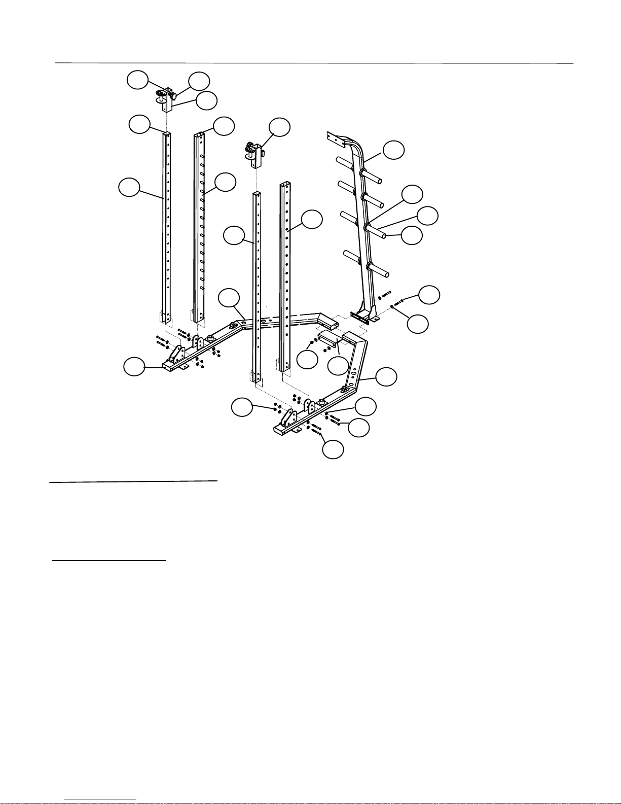
ASSEMBLY INSTRUCTIONS ASSEMBLY STAGE #1
AssemblyHardwareRequired:
#30 ButtonHeadAllenScrew Qty. 2 #40 FlatWasherQty.20
#32 ButtonHeadAllenScrew Qty. 4 #42 NylonNut Qty.10
#33 ButtonHeadAllenScrew Qty. 4
AssemblyDescription:
A) SECRULY assemblethe RearUpright (#3)tothe Left Base (#1)and RightBase (#2)using1- L
Bracket (#20), 2- ButtonHeadAllenScrews (#30), 4- FlatWashers (#40),2- NylonNuts (#42)
asshown.
B) SECRULY assemblethe RightOlympicBarSupport (#6)and the LeftOlympicBarSupport
(#7)tothe RightBase (#2)and Left Base (#1) respectively using2- ButtonHeadAllenScrews
(#32),4- FlatWashers (#40),2- NylonNuts (#42)onperside.
C) Assemble the RightVerticalTubeAdjustable (#5)andthe LeftVerticalTubeAdjustable (#4)to
the RightBase (#2)and LeftBase (#1) respectively using 2- ButtonHeadAllenScrews(#33),
4- FlatWashers (#40), 2- NylonNuts (#42)onperside.
D)Slide theLeft HandleAdjustable(#8)andthe Right HandleAdjustable(#9)tothe LeftVertical
TubeAdjustable (#4)and the Left VerticalTubeAdjustable (#4) respectively andtightwithPop
pinsasshown.
Page 7
8
9
47
56
1
2
30
40
20
42
32
40
42
33
60 61
61
66
67
68
70
69
3

ASSEMBLY INSTRUCTIONS ASSEMBLY STAGE #2
AssemblyHardwareRequired:
#34 ButtonHeadAllenScrew Qty. 1 #41 FlatWasherQty.2
#43 NylonNut Qty. 1
AssemblyDescription:
A)Insert the LinearShaft (#22)intothe LeftBase (#1)and tighten itwiththe set screw. Carefully
slide 1 –Bumper (#46), 1 –LeftOlympicBarAdjustable (#11), 1 –Bumper (#46), 1 –Olympic
BarAdjustable (#10)asshown.
B)Insert the LinearShaft (#22)intothe RightBase (#2)andtightenit withtheset screw. Carefully
slide 1 –Bumper (#46), 1 –RightOlympicBarAdjustable (#23), 1 –Bumper (#46),1 –
OlympicBarAdjustable (#10)asshown.
C)Slide 2 –Weightstackcushion (#44)downoverthe GuideRod (#21)andinsert 2 –GuideRod
(#21)intothe LeftBase (#1)& RightBase (#2)asshown.
D)Using EXTREMECAREslide all9 –WeightPlate overthe GuideRod (#21)on tothe Weight
Stack Cushion (#44)on perside. Makesurethat the Weight Plateareallfacingasshown.
E)Slide the TopWeightAssy (#28)downoverthe GuideRod (#21)ontothe WeightStack;please
be morecarefullyof theweights.
F) SECRULY assemblethe FootPlate (#18)to LeftBase (#1)or RightBase (#2)using 1- Button
HeadAllenScrew (#34),2 –FlatWasher (#41)and 1 –NylonNut (#43)asshown.
Page 8
22 21
11
46 44 10
28
44
18
34 41
43
58
(9pcs x 2 stacks)
10
62
63 23
64

ASSEMBLY INSTRUCTIONS ASSEMBLY STAGE #3
AssemblyHardwareRequired:
#31 Button Head Allen Screw Qty. 2#40 FlatWasherQty.16
#32 Button Head Allen Screw Qty. 2#41 FlatWasher Qty. 8
#33 Button Head Allen Screw Qty. 4#42 Nylon Nut Qty. 8
#36 Button Head Allen Screw Qty. 4#43 Nylon Nut Qty. 4
AssemblyDescription:
A) SECRULY assemblethe RightTop Brace (#12)andthe LeftTop Brace (#13)tothe RearBase
(#3)using 1 –LBracket (#19), 2 –ButtonHeadAllenScrew (#32),4- FlatWasher (#40)and 2-
Nylonnut (#42).
B)Tight the LinearShaft (#22),the GuideRod (#21)tothe Top Brace withSet Screwson perside
asshown.
C) SECRULY assemblethe 2–Top Beam (#17)tothe Top Brace and the OlympicBarSupport
using2 –ButtonHeadAllenScrew (#36), 4 –FlatWasher (#41),2 –NylonNut (#43), 2 –
ButtonHeadAllenScrew (#33), 4 –FlatWasher (#40)and2 –NylonNut (#42)on perside as
shown.
D)Assemblethe SwivelingPulleyHandles (#16)tothe LeftHandleBarAdjustable (#8),the Right
HandleBarAdjustable (#9)using2 –Button HeadAllenScrews (#31), 4 –FlatWashers (#40)
and 2 –NylonNuts (#42)asshown.
Page 9
17
36 41 43
33
40
31
40
16
42
12
13
19 32
40
72
65

ASSEMBLY INSTRUCTIONS AssemblyStage#4
AssemblyHardwareRequired:
#32 ButtonHeadAllenScrew Qty. 4 #40 FlatWasherQty.8
#42 NylonNut Qty. 4
AssemblyDescription:
A)Assemblethe Top Bar (#14)tothe TopBeam (#17)using4 –ButtonHeadAllenScrews (#32),8
- FlatWashers (#40)and 4 –NylonNuts (#42)asshown.
B) SECRULY insert the OlympicBarShaft (#26)intothe OlympicBar (#25)and slide1 –Bumper
(#45),1 –PlasticSleeve (#48)and1 –InsideBumper (#47)on persideasshown.
Page 10
32 40
19
48
45
25
26
19
19
19
17
14
42

CABLEPULLEYASSEMBLY/ORIENTATION
AssemblyHardwareRequired:
#36 ButtonHeadAllenScrew Qty. 4#43 NylonNut Qty.22
#37 ButtonHeadAllenScrew Qty. 2#49 StepSpacerQty. 4
#38 ButtonHeadAllenScrew Qty. 6 #50 StepSpacer Qty.12
#39 ButtonHeadAllenScrew Qty.10 #51 StepSpacer Qty. 2
#41 FlatWasher Qty.24
AssemblyDescription:
Followthe assemblyorientationand referencethe hardwarecall-out#shownforeachpulleylocation.
Looselymount allthepulleys inposition sothat theymaybe easilyremoved forcablerouting
assembly.
AssemblyNote: The 3.5inchCablePulley(#53)must be positioned assemblylocations.
Page 11
36 51
43
41
39
(2pcs) (2pcs)
(2pcs)
(4pcs) (8pcs)
(2pcs)
43
39
(2pcs)
(4pcs)
41 (2pcs)
43
(2pcs)
36
(4pcs)
49
(2pcs)
43
(2pcs)
37
(4pcs)
41
(2pcs)
43
(6pcs)
38
(2pcs)
50
(2pcs)
43
(4pcs)
43
(2pcs)
27
(8pcs)
41
(4pcs)
39

CABLEPULLEYASSEMBLY/ORIENTATION
AssemblyHardwareRequired:
#35 ButtonHeadAllenScrew Qty. 2 #41 FlatWasherQty.4
#43 NylonNut Qty. 2
AssemblyDescription:
A)Threadthe bolt-endof the LatCableAssembly (#56)intothe SwivelingPulleyHandles (#15).
RoutetheCablethrough the seriesof upperpulleysanddowntothePulleyonthe PulleyBracket
(#27)and uptothetwoPulleys anddowntermination intothe Selector/Top PlateAssembly
(#28),Donot fullytightenthe lockingnut ormakecableadjustmentsuntilallthe assembleshave
been properlyrouted.
B) Routethe LowerCableAssembly (#55)fromthe SwivelingPulleyHandles (#15)through the
bottomPulleyand BaseTube and the otherPulleyand uptothe pulleyon the PulleyBracket (#27)
and downtothe BaseTube tight with1 –ButtonHeadAllenScrew (#35), 2 –FlatWasher (#41)
and 1 –NylonNut (#43).
C) Repeat theassemblyA)&B)on the otherside.
Page 12
54 Handle Strap 2pcs
55 Lower Cable 2pcs
56 Lat Cable 2pcs
57 Selector Pin 2pcs
Congratulations!
You have completed the assembly of this product and you are ready to atart exercising toward a healthier lifestyles!
52
35
41
43

PreventativeMaintenance EquipmentMaintenance
Useadampened soft clothtowipe the equipmentfree of perspiration aftereachuse. Do notuseabrasivecleanersor
petroleum-based solventstoclean the equipment.
Regularlyinspect productforlooseassemblyhardwareand worncomponents.
Basicrepairscan be performed bythe customer.Moreadvanced (technical)repairsshouldbe performed byan
authorized serviceprovider.
Useaproduct / exercisemat underneathequipment forprotection offloorsand carpets.
(Ifapplicable)Applyrecommended componentlubricantsat the required timeperiods.
Keep productmanuals,purchasing receipt, and servicerecordsinsafestorage place.Thisinformation maybe needed
forfuturereference.
Do not useorstoreequipment outdoors.
Moving equipment: Makesureequipmentisfree ofindividual weight platesand useframewheels(ifapplicable)to
maneuvertothe desired location.Itisrecommended thatmorethan one person assist inthe movementof heavystrength
equipment.
Training Tips
Howyou start an exerciseprogramdependson yourphysicalcondition.Ifyou havebeen inactiveforawhileoryou have
pre-existing healthcondition, you shouldstart slowly.Initiallyyou mayonlybe ableexerciseforashort amountoftime
using minimal resistancelevelsorweightloads.
Beginyourdesired training programslowlyand graduallyincreasethe amount of timeyou exercise.Applyrealisticgoals,
that havebeen set byyouoryourphysician. You should see sufficientgainsinyourpersonalfitness levelwithin 6-8weeks
of continuousexercise, butdo not bediscouraged if it takeslonger. Itisvery importanttoexerciseat yourownpaceand
becomeconfidentinobtaining yourgoals.It isalsoimportanttoapplywarm-up, stretching,and cooldownperiodswithany
exerciseprogram.
Asyourfitness levelincreases, sowillyourconfidenceand senseofaccomplishment.
Regularlyexerciseand ahealthydiet willenergizeyou and offerasenseofwell-being.
Page 13

LS 541N
Table of contents


