Smith FS351SP User manual
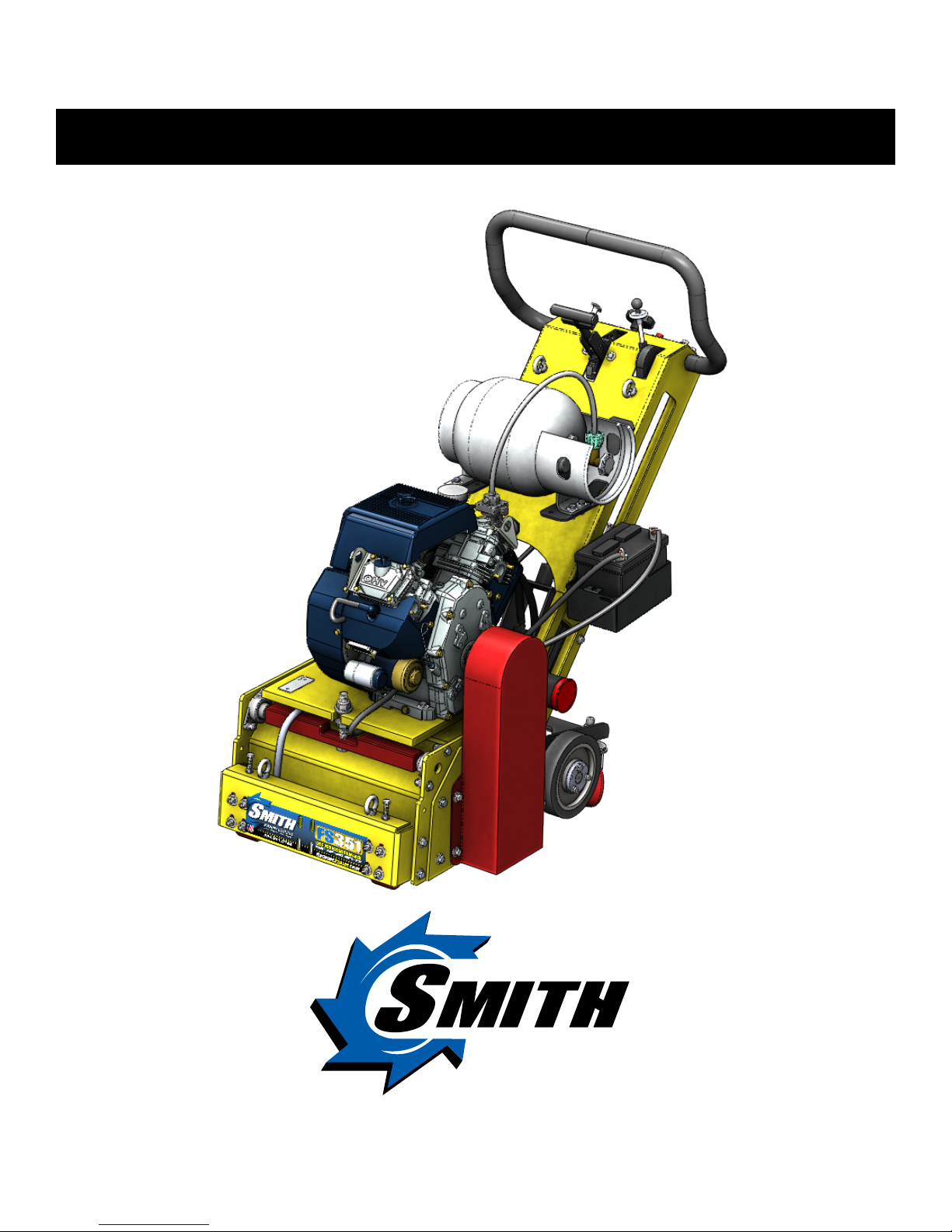
FS351SP Propane
Heavy Duty Self Propelled Remover
User Manual
(954) 941-9744
www.SMITHMFG.com
MANUFACTURING
Cutters / Removers / Parts / Support
1-800-653-9311
www.SmithMfg.com
Phone: 954-941-9744 • Fax: 954-545-0348

SMITH Manufacturing 1-954-941-9744 www.SmithMfg.com
FS351SP
VERSION 11/2016
Propane
2
SMITH Manufacturing 1-954-941-9744 www.SmithMfg.com
INTRODUCTION
Congratulations on purchasing the
FS350™ heavy duty remover from
SMITH Mfg. Company.
Your machine will:
• Clean surfaces impacted by grease, oil,
plastics, tars, resins, tile adhesives, ice and
more
• Plane or mill asphalt and concrete surfaces
• Remove high spots in curbs and gutters
• Eliminate trip-hazards on concrete sidewalks
• Mill areas for rumble strips
• Clean out cracks and joints
• Create anti-slip patterns in walkways and barns
• Prepare surfaces for new coating applications
• Permanently remove all road and surface
coatings to include:
epoxy, urethane, thermoplastic, paint,
glue-backed tapes and more...
• Groove-inlay asphalt for striping
BEFORE START-UP,
READ THIS..
Please read all operating instructions, including
the provided motor manual and be completely
familiar with your equipment before operating.
When in doubt, please contact SMITH
Manufacturing Customer Service for operational
details. This Owner’s Manual will guide you
through the removal process, from start to nish,
and show you how to care for your machine.
UNCRATING EQUIPMENT
When you uncrate your equipment, make
certain that the machine has not been damaged
and that all fasteners and guards are properly
tightened.
Your machine may not have been shipped
assembled with cutters and other accessories.
Assembly may be required.
REMEMBER: Only authorized, experienced and
properly trained personnel should operate this
equipment. Operating personnel should practice
safety at all times and wear protective gear
(gloves, goggles, safety vests, ear plugs, steel-
toe shoes, etc.)
Page Contents
2Index / Introduction
3Safety Guidelines
4Your FS351SP Surface Preparator
5Handle Adjustment Instructions
6Machine Start-Up
7Substrate Removal
8Storage, Ordering, and Warranty Claims
9Troubleshooting
10 Maintenance Check List, Front Wheel Adjustment
11-13 Drum / Belt Replacement and Alignment
14-15 Bearing Replacement
16-17 Cutter Drum Options
18-19 Maintenance Log
20 Limited Equipment Warranty
21 Warranty Activation
CONTENTS
SMITH Manufacturing 1-954-941-9744 www.SmithMfg.com
SMITH Manufacturing 1-954-941-9744 www.SmithMfg.com
VERSION 11/2016
FS351SP
Propane
3
• Always wear protective equipment, including
ear protection and goggles.
• Never wear baggy or loose tting clothing that
can be caught on controls or moving parts.
• The surface preparator can emit ying
particles and debris during operation. Never
operate the machine near bystanders, animals
or children.
• Check uid levels and get acquainted with the
controls.
• Do not operate the machine in an explosive
atmosphere, near combustible materials, or
when gas fumes may not be properly dispersed.
• Never leave the machine unattended when
running, and you must hold onto the handle with
two hands when the cutter drum is engaged.
• Ensure that all guards are in place before the
machine is operated, since rotating and moving
parts will cause injury upon contact.
• Always make sure that main
fuel valve is turned OFF when
storing machine.
Incorrect use of the surface planer can
result in property damage, personal injury,
or death. Be sure to read and follow all
directions and precautions as outlined in
this manual.
SAFETY GUIDELINES
DUST RESULTING FROM USE OF THIS MACHINE AND CUTTER
TOOLS MAY INCLUDE CHEMICALS PROVEN TO CAUSE CANCER,
BIRTH DEFECTS, AND REPRODUCTIVE CONTRAINDICATIONS,
INCLUDING LEAD FROM SOME PAINTS AND SILICA FROM
CONCRETE AND MASONRY. ALWAYS OPERATE THIS MACHINE
IN A WELL-VENTILATED AREA WITH A HEPA FILTER DUST
CONTAINMENT VACUUM SYSTEM. OPERATORS SHOULD ALWAYS
WEAR PROPER SAFETY EQUIPMENT, INCLUDING AN APPROVED
RESPIRATOR TO FILTER OUT FINE DUST PARTICLES. ALL EPA
AND OSHA GUIDELINES REGARDING AIRBORNE DUST SHOULD
BE FOLLOWED WHEN OPERATING THIS MACHINE. FAILURE TO
FOLLOW THESE SAFETY PROTOCOLS MAY RESULT IN SERIOUS
INJURY, ILLNESS, OR DEATH
SMITH Manufacturing 1-954-941-9744 www.SmithMfg.com
FS351SP
VERSION 11/2016
Propane
4
SMITH Manufacturing 1-954-941-9744 www.SmithMfg.com
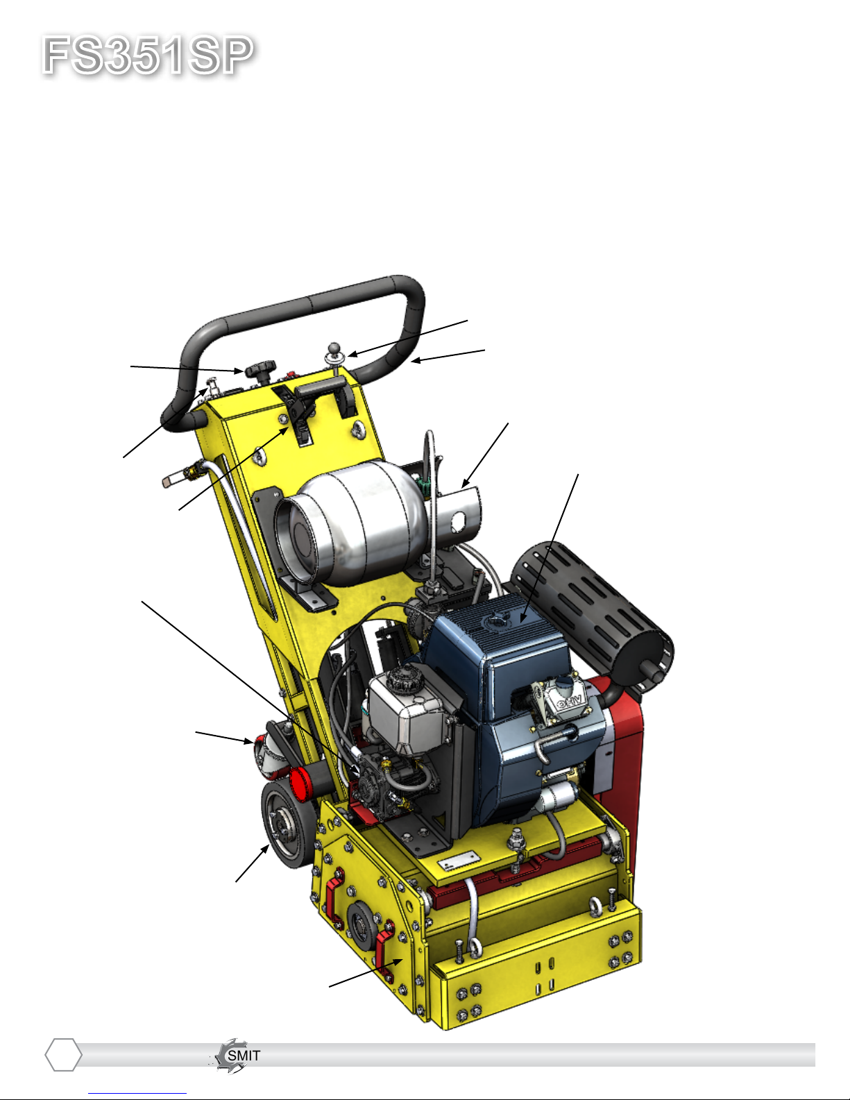
YOUR FS351SPTM SURFACE PREPARATOR
Please take time to familiarize yourself with the FS351SP™’s controls, as well as
some of the features of your new machine.
Read the engine manual before preparing the engine for starting.
Adjustable Handlebar
Forward/ Reverse control lever
Fine Cutter Height
Adjustment
Lifting carriage with
swivel casters
Air intake / ltration system
Hydraulic drive pump
Removable Side Plate
Self propelled drive wheels
Throttle Control
Height Adjustment
T-Handle
Aluminum Propane Tank
SMITH Manufacturing 1-954-941-9744 www.SmithMfg.com
SMITH Manufacturing 1-954-941-9744 www.SmithMfg.com
VERSION 11/2016
FS351SP
Propane
5
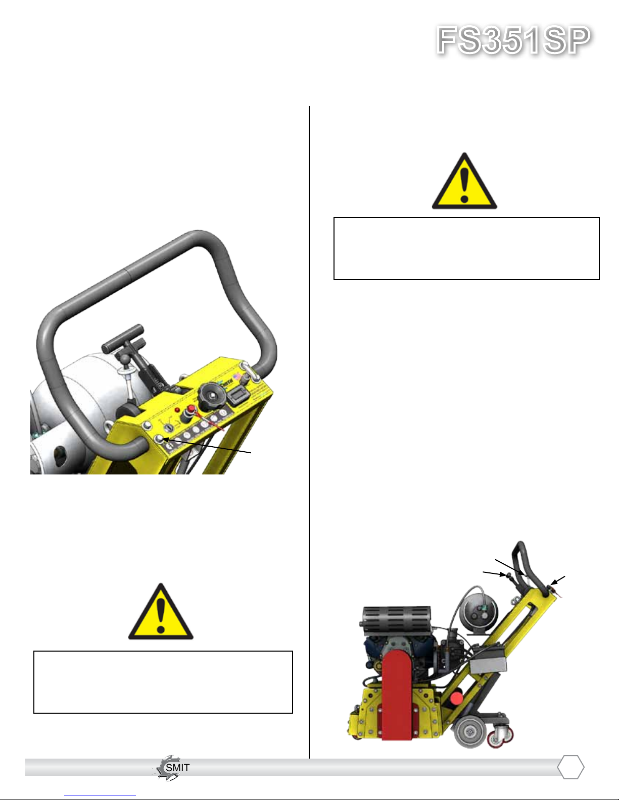
HANDLE BAR ADJUSTMENT
The handlebars are equipped with a high-density
vibration suppression material to minimize
operator fatigue and increase comfort level when
operating equipment. To adjust the handlebars
to a new position for different height operators
please follow these steps:
• Using a wrench or socket (9/16”), loosen
the bolts on both sides of the handlebars
two to three turns only.
• Adjust handlebar to desired position and
re-tighten the 4 screws
Never operate with handlebars loose.
The bolts must be fastened tightly assuring
the handle is locked into position.
Loosen to
adjust
HYDROSTATIC OPERATION
Check to insure the hydrostatic drive system
is in neutral. The control lever should be in the
middle position and the wheels should not be
turning. Lower the unit by moving the Cutter
Height Adjustment T-Handle into position. This
will raise the carriage wheels off the ground and
set the unit onto the drive wheels. At this point
the unit can be propelled forward or in reverse
by moving the drive lever either forward or
backward. The Fine-Adjustment Knob may be
used to make small corrections in height. The
“live” axle will tend to move the unit in a straight
line, however both hands are required on the
handle for safe operation and minor directional
corrections. For more aggressive directional
changes or repositioning requirements, simply
reengage the lift carriage by using the Height
Adjustment T-Handle.
RUN SPEED for Diamond Cutters is wide
open (3200 rpm) .
The Max RUN SPEED for Drums is 1100 rpm
(lower may be used).
Engine must be warmed up and at RUN SPEED.
Height Adjustment
T-Handle
Control Lever
Fine Adjustment
Knob

SMITH Manufacturing 1-954-941-9744 www.SmithMfg.com
FS351SP
VERSION 11/2016
Propane
6
SMITH Manufacturing 1-954-941-9744 www.SmithMfg.com
MACHINE START-UP
Do not start machine while drum is in
contact with the ground. Doing so can
cause the operator to lose control of the
machine, resulting in property damage
and/or personal injury.
NOTE: Do not attempt to raise or lower the cam
lever by force. If it does not move effortlessly,
raise or lower the hand wheel until the cam lever
can be adjusted. Open the propane tank supply,
then lock the throttle lever at the “Fast Idle”
position. Start the engine, then, move throttle
control to open or run position when engine
is warmed up. Increase throttle to maximum
operating position (approx. 2800RPM) and
close choke. Before substrate removal, test run
the drum with cutters not touching the surface.
If there is excessive vibration, you need to
re-balance the cutter set-up, check bearing
condition, and/or make sure that the drive shaft
is secured.
Corded “Engine Kill” Button: In the event
of a malfunction or an accident (such as the
machine operator falling or losing footing), the
FS351SP is equipped with a corded “Engine
Kill” Button. Attach the end of the cord to the
operator’s belt or wrist, and snap the clip into
place on the stop switch by raising the top of
the Engine Kill Button and inserting the clip into
the gap. If the operator becomes distanced too
far from the machine, the cord will detach from
the stop switch, and the machine will stop run-
ning.
Attatch to
operator
*NOTE: the Engine will not start without the
Corded Engine Kill’s clip securely in place.
CAUTION: The machine will still move with
the engine off.
IF THE ENGINE DOES NOT
START
1) Check Engine for proper fuel and oil levels
(refer to Engine manual)
2) Check spark plug. Make sure the socket
areas are clean and clear of debris, and that
the proper gap is set. (Replace if needed).
3) Turn the On/Off switch, on the Control
Panel, to “On”.
4) Check Corded Engine Kill Button’s
Connections:
a) Make sure the Corded Safety Stop “C”
Connector is dipped properly.
b) Try switching the connection to the
opposite post (From letter “C” to letter
“M”, for example).
*Engine repair and engine warranty
issues are handled directly
by your local engine service center.

SMITH Manufacturing 1-954-941-9744 www.SmithMfg.com
SMITH Manufacturing 1-954-941-9744 www.SmithMfg.com
VERSION 11/2016
FS351SP
Propane
7
SUBSTRATE REMOVAL
Adjust the height of the cutter drum with the
Hand Wheel and T-Handle. (Turn the hand
wheel to raise the cutter drum off of the
substrate. Lower or raise the T-Handle to
engage or disengage the drum after setting
the proper cutter depth.)
Set the depth of cut to allow the cutters to go
through only the materials to be removed.
Make certain that the drum is positioned to
where only the cutters strike the surface,
and that the drum assembly never comes
into contact with the substrate. The cutter
tips alone should strike the surface (1/8”
to 1/4” maximum depth per removal pass on
new cutters).
The drum will not withstand substrate
contact. Contacting the removal surface
too deeply will cause premature wear
to cutters, shafts, drum and other
components!
Too much downward pressure only has
negative results. Try to remove materials
in several passes rather than one, deep
pass. Several tests will show the best, most
appropriate cutter impact. Use a forward,
backward and/or circular pattern to achieve
your desired nish.
NOTE: Only use a forward motion when the
CM2150 or CM2550 carbide milling cutters
are used.
TIP: Positioning the machine over the
surface in many directions, as well as dialing
the hand wheel up or down can help create
desirable surface patterns.
After several hours of practice, the operator
will become comfortable and should be able
to remove materials faster with enhanced
results.
When the job is completed, or the operator
wants to cease work, stop the engine by rst
lifting the drum above the substrate using the
hand-wheel and/or the T-Handle. Stop the
machine only at the engine. Then close the
Propane Supply Valve on the tank to shut off
the fuel supply.
The drum assembly must be removed daily
and inspected for drum wear, hole elongation
and possible weld separation. Replace the
cutter shafts every 40 hours, or prior to any
drum wear. If the drum’s center holes are
elongated, order another SMITH cutter drum.

SMITH Manufacturing 1-954-941-9744 www.SmithMfg.com
FS351SP
VERSION 11/2016
Propane
8
SMITH Manufacturing 1-954-941-9744 www.SmithMfg.com
STORAGE
Shut off the main valve on the tank and dis-
connect the gas line.
ORDERING
To ensure product safety and reliability,
and to maintain your warranty, always use
genuine replacement cutters and parts from
SMITH when making repairs to equipment.
When ordering please specify the model and
serial number of the machine. In addition, give
a part number, description, and quantity as
listed on your parts list.
If you have any questions about the operation
of your machine or would like to order
replacement parts, contact your SMITH
Manufacturing representative directly.
Contact 1-800-653-9311 (954-941-9744)
for information.
Visit our website at
www.smithmfg.com
WARRANTY CLAIMS
The manufacturer reserves the right to
change or improve the machine design
without assuming any obligation to update
any products previously manufactured
before this manual. It is the customer’s
responsibility to complete the warranty
card and mail it to the seller within 10 days
from date of purchase. If a failure occurs
during the warranty period, the customer
must contact the seller to determine the
appropriate action.
Any and all transportation charges are to
be borne by the purchaser.
Always make sure that main
fuel valve is turned OFF when
storing machine.

SMITH Manufacturing 1-954-941-9744 www.SmithMfg.com
SMITH Manufacturing 1-954-941-9744 www.SmithMfg.com
VERSION 11/2016
FS351SP
Propane
9
TROUBLESHOOTING
PROBLEM
Possible Reason(s)/Solution(s)
CUTTERS WEARING
UNEVENLY/PREMATURELY
Drum is too low
Incorrect set-up
Material Build-up
Cutters too tightly loaded
Wrong cutters for
application
CUTTERS SHAFT BREAKAGE
UNEVENLY/PREMATURELY
Drum is too low
End plates or bushings worn
Shafts worn
Wrong cutter set-up
Over 40 hours service-life
DRUM WEARING
PREMATURELY OR CRACKING
Drum hitting ground
Shafts and bushings not replaced
within 40 hours
EXCESS VIBRATION
Bearing worn
Hex bushing worn
Drive shaft worn
Improper cutter set-up
Drum contacting ground
Wheels worn out
MACHINE JUMPS
ERRATICALLY
Drum hitting ground
RPM is too low
Surface is severely uneven
DRIVE BELT WEARING
PREMATURELY
Pulley is misaligned
Wrong belt
Drum is contacting
the surface
MACHINE WONT MOVE IN
FORWARD OR REVERSE
Check hydraulic reservoir level
Verify v-belt to hydraulic pump
is not slipping or damaged
*Engine repair and engine warranty
issues are handled directly
by your local engine service center.
For any other problems or questions,
please contact your local representative
or
SMITH Mfg today at 800-653-9311
or
(954) 941-9744.
Check lifting carriage is in
upright position and drive
wheels in contact with ground

SMITH Manufacturing 1-954-941-9744 www.SmithMfg.com
FS351SP
VERSION 11/2016
Propane
10
SMITH Manufacturing 1-954-941-9744 www.SmithMfg.com
MAINTENANCE CHECK LIST
Note: Make sure the ignition is in the OFF
position, and spark plugs are disconnected
before servicing
• Maintain proper engine oil and crankcase
levels.
Change every 25-50 hours
(see Subaru manual).
• Clean spark plugs regularly, and set the
proper gap.
• Wash the air cleaner element in a non oil-
based solvent, then squeeze out residue.
Allow lter to dry before reinstalling in cleaner.
• Keep a coating of grease on the drive shaft
and threads for easy installation or removal,
and for longer hex bushing life.
• Check all fasteners and re-tighten, since the
machine will vibrate the fasteners loose if they
are not secured. Use locktite.
• Check the Drive and Hydraulic belts for wear,
and adjust (tension), or replace as required.
After replacing belts, check for proper tension:
• Check that the pulleys are aligned properly
to ensure the Drive and Hydraulic belts are
running true.
• The inside housing must be clean, and
remove any build-up from inside the cage so
cutters and drum rotate freely.
• Inspect and change drum bushings and
shafts every 40 hours, or when worn.
• Ensure Hydraulic uid level reservoir is lled
to the proper level and inspect ttings for
leaks. Tighten as necessary.
The hydraulic uid for the hydraulic drive pump
should be chemically stable and incorporate
rust and oxidation inhibitors.
Specic uid type meeting these requirements:
*Non-Detergent SAE 20W-20 Motor Oil
Note: If the natural color of the uid has become
black or milky, it is possible that an overheating
or water contamination problem exists. For ac-
curate level readings, take readings when uid
is cold.
FRONT WHEEL ADJUSTMENT
The front wheels can be adjusted independently.
1. Loosen, but don’t remove the 4 nuts
holding the wheel to be adjusted
2. Adjust wheel height as needed using height
adjustment bolt.
3. Tighten all nuts to secure wheel into
position.
2)
1)

SMITH Manufacturing 1-954-941-9744 www.SmithMfg.com
SMITH Manufacturing 1-954-941-9744 www.SmithMfg.com
VERSION 11/2016
FS351SP
Propane
11
DRUM REPLACEMENT
Drum replacement is easy and requires a
few hand tools.
1. 9/16” socket or wrench
2. Rubber mallet
Before beginning servicing on any
propane-powered unit,
DISCONNECT SPARK PLUG WIRES!
1. Lower the machine so the cutter drum
is resting on the ground. Do this with the
cutter height adjustment T-handle.
4. Slide out drum assembly. (use caution as
it is HEAVY)
2)
3)
4)
5. Once the cutter drum is removed take to a
workbench for assembly.
a) Inspect condition of cutters,
spacers, shafts, bushings and drum.
6) Before replacing the drum onto hex shaft:
a) Check that all bearings are in
good working order
b) Remove dirt and material build-up
from inside drive carriage and drum.
c) Lubricate shaft and drum bushings
with synthetic dry lube.
d) Make sure to replace drum spacers
and that they are properly seated.
7) Align and slide drum back onto the hex
shaft.
8) Replace side plate (lift-up and lock into
place) over hex shaft and secure hardware.
NOTE: It is recommended that you use a
wooden board or something similar to place
under the drum before lowering the machine
to take the drum weight off the shaft which
makes it easier to align with side plate
2. Remove the six hex head cap screws
from the side plate using the 9/16” socket
or wrench.
3. Remove the side plate (this may require
the rubber mallet to break it loose)
*TIP: SMITH recommends owning an
extra drum loaded with cutters for
rapid job-site work ow.
6d)
6d)

SMITH Manufacturing 1-954-941-9744 www.SmithMfg.com
FS351SP
VERSION 11/2016
Propane
12
SMITH Manufacturing 1-954-941-9744 www.SmithMfg.com
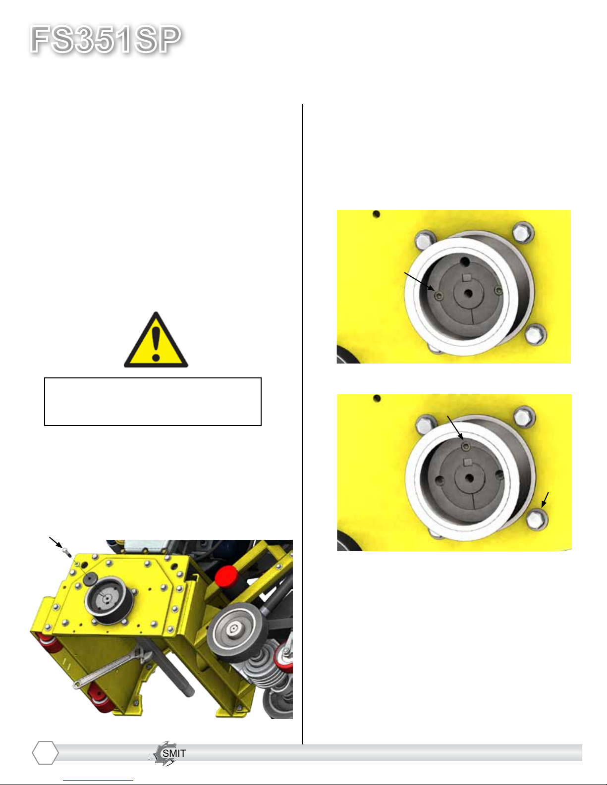
DRUM REPLACEMENT CONT’D.
Your drum may be equipped with the newly
revised drum retention design. This can
be identied by the three (3) set-screws
on either side of the of the drum, and the
notch cut out from the Bearing Housing.
To remove this type of drum, you will rst
need to remove the set-screws.
Before beginning servicing on any
propane-powered unit,
DISCONNECT SPARK PLUG WIRES!
1.) After making sure that the engine is
off and either disconnecting the battery
or removing the spark-plug wires, rotate
the drum so that the rst set-screw on
the side of the drive-belt lines up with the
notch in the Bearing Housing. If the drum
is too difcult to rotate, you may need to
loosen the drive-belt. Refer to Pg. 13 for
instructions on loosening the drive-belt.
1)
3.) Remove the Sideplate, as described on
Pg. 11.
4.) You now have access to remove the
remaining three (3) set-screws on the other
side of the drum.
5.) Once all six (6) set-screws have been
removed, you are now able to slide out and
remove the drum as described on Pg. 11.
6.) To replace the drum, slide it onto the
shaft, then secure the six (6) set-screws in
the same way they were removed.
3)
4)
2.) Once the rst set-screw is removed,
rotate the drum to remove the remaining
set-screws in the same way.

SMITH Manufacturing 1-954-941-9744 www.SmithMfg.com
SMITH Manufacturing 1-954-941-9744 www.SmithMfg.com
VERSION 11/2016
FS351SP
Propane
13
DRIVE BELT REPLACEMENT
Normal wear may necessitate belt
tensioning or replacement.
Time of replacement will vary according to
usage and belt load factors.
Replacement is easy and requires a few
hand tools.
1. 9/16” socket or wrench
2. 1-1/16” open box wrench
Before beginning servicing on any
propane-powered unit,
DISCONNECT SPARK PLUG WIRES!
4. Using a 9/16” socket or wrench, remove
the four hex nuts attaching the belt cover to
the side of the machine. Remove the cover
and set it aside.
2)
4)
5. Turn the Base Plate Pivot Nut with a 1-1/16”
socket or wrench to lower the engine base
plate and loosen the drive belt.
Remove / replace the belt as needed
6. To tension the belt, turn the Base Plate
Pivot Nut with a 1-1/16” wrench to raise the
engine base plate.
DO NOT overtighten the belt as it will cause
it to wear prematurely. The belt should be
able to deect 1/4” when pressing on it.
7. Put the belt cover back in place and
secure the four hex nuts with a 3/8” socket
or wrench.
2)
5)
3. Clean the machine exterior so you can
locate all the appropriate parts.
1. Make sure the removable side plate is
installed. This insures the drive ends are in
the proper position for servicing.
2. Disconnect the spark plug wires
SMITH Manufacturing 1-954-941-9744 www.SmithMfg.com
FS351SP
VERSION 11/2016
Propane
14
SMITH Manufacturing 1-954-941-9744 www.SmithMfg.com
BEARING REPLACEMENT
Before reading ahead go back and follow
the instructions on how to remove the drum
and drive belt from the machine. Bearing
replacement is easy and requires a few
additional hand tools.
1. 17 mm socket or wrench
2. 9/16” socket or wrench
3. Adjustable wrench up to 1.5”
4. 7/32” Hex Key
Before beginning servicing on any
propane-powered unit,
DISCONNECT SPARK PLUG WIRE!
1. With the side plate off the machine, use a
wrench to lock the rotation of the shaft.
Using the 9/16” socket, remove the screw
that locks down the pulley to the shaft.
2. With the shaft rotation still locked, use a
7/32” hex key to remove the 2 set screws on
the drive pulley (A). Once they are removed,
insert one of them into the hole directly on
top of the keyway to back out the bushing
as shown below (B).
1)
2A)
2B)
4. With the bearing housing assemblies
aside, they can now be taken apart to
replace the bearings as needed using the
circlip pliers.
3)
3. With the Pulley removed, use the 17 mm
socket or wrench to remove the bearing housing
assembly from the frame and from the side plate .

SMITH Manufacturing 1-954-941-9744 www.SmithMfg.com
SMITH Manufacturing 1-954-941-9744 www.SmithMfg.com
VERSION 11/2016
FS351SP
Propane
15
BEARING REPLACEMENT
(CONTINUED)
5. The bearing assembly shown below.
Side plate side
bearing housing
Belt side bearing
housing
***WARNING***
When pressing bearings in, use a soft wooden
dowel and only apply pressure to the outer race
of the bearings
DRIVE PULLEY REPLACEMENT
The drive pulleys may be replaced to change
between diamond mode and ail mode.
For ail mode, use a 28-tooth pulley on the
engine shaft and a 56-tooth pulley on the drum
shaft with a 1064 mm belt. The engine should be
run at 2500 RPM.
For diamond mode, use a 48-tooth pulley on the
engine shaft and a 48-tooth pulley on the drum
shaft with a 1120 mm belt. The engine should be
run at 3200 RPM.
Before attempting to change Drive Pulleys,
go back and follow the instructions on how to
remove and replace the Belt Cover, Drive Belt,
and Drive Pulleys from the machine.
Flail Mode Diamond Mode
FLAIL DRUMS MUST BE USED ON
MACHINES IN FLAIL MODE ONLY.
USING FLAIL DRUMS IN DIAMOND
MODE MAY RESULT IN DAMAGE TO THE
MACHINE AND INJURY OR DEATH TO
THE OPERATOR AND BYSTANDERS.
SMITH Manufacturing 1-954-941-9744 www.SmithMfg.com
FS351SP
VERSION 11/2016
Propane
16
SMITH Manufacturing 1-954-941-9744 www.SmithMfg.com
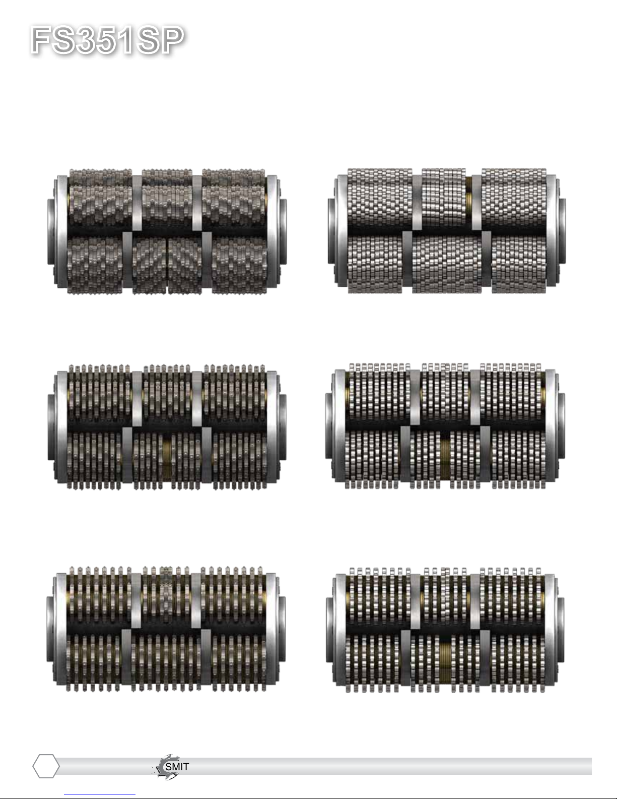
CUTTER DRUM OPTIONS
SMITH Cutter Drums are custom built to suit your specic needs. Below are some common examples.
Be sure to contact your SMITH Sales Representative for assistance with picking the drum options that are right
for your applications.
5-Shaft Flail-It Drum
Coarse Pattern
F350.15.25.3158.15C
5-Shaft Flail-It Drum
Fine Pattern
F350.15.25.3158.15F
FLAIL-IT STRIP-IT
5-Shaft Flail-It Drum
Medium Pattern
F350.15.25.3158.15M
5-Shaft Strip-It Drum
Coarse Pattern
F350.15.25.411.15C
5-Shaft Strip-It Drum
Fine Pattern
F350.15.25.4116.15F
5-Shaft Strip-It Drum
Medium Pattern
F350.15.25.4116.15M
SMITH Manufacturing 1-954-941-9744 www.SmithMfg.com
SMITH Manufacturing 1-954-941-9744 www.SmithMfg.com
VERSION 11/2016
FS351SP
Propane
17
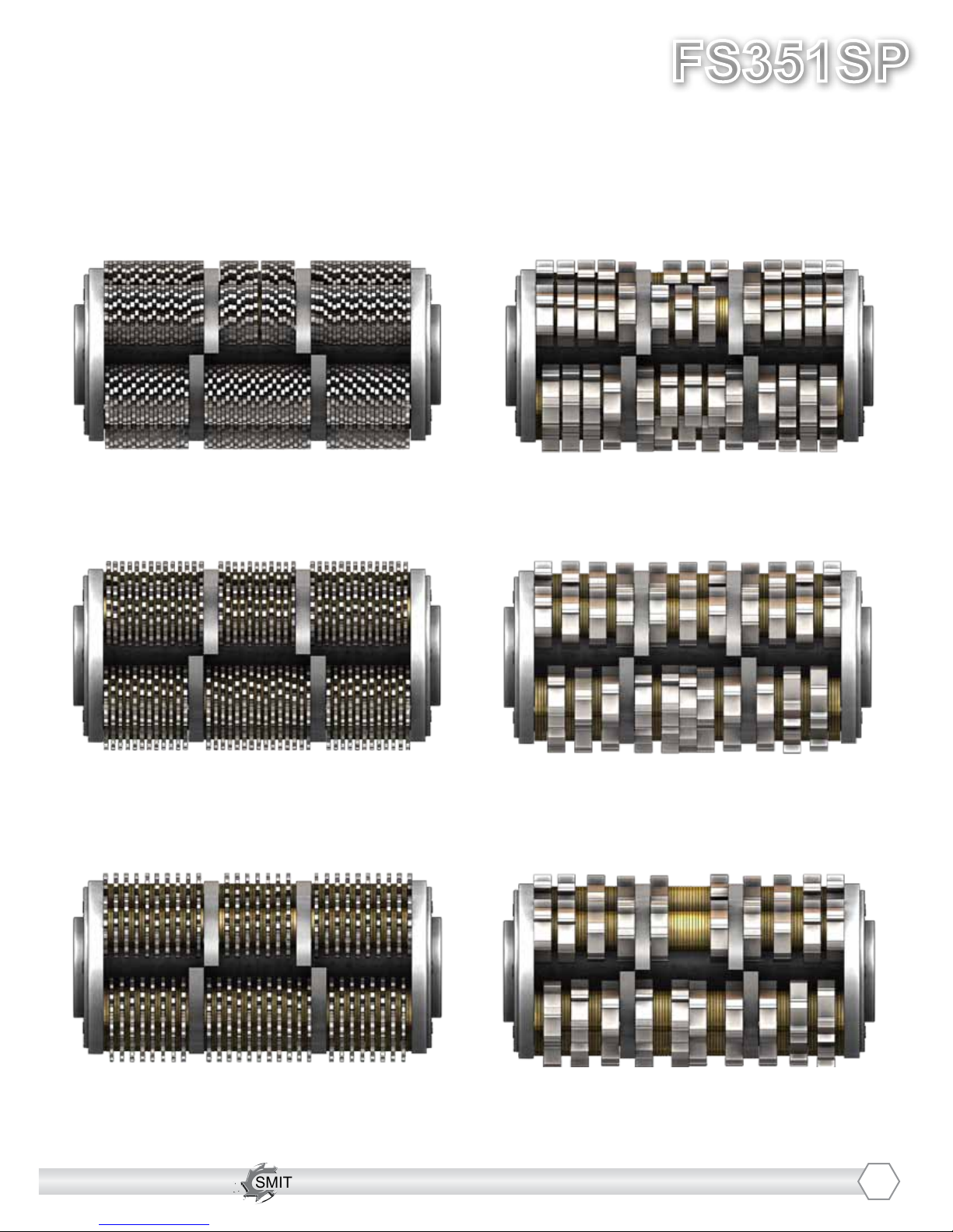
CUTTER DRUM OPTIONS
SMITH Cutter Drums are custom built to suit your specic needs. Below are some common examples.
Be sure to contact your SMITH Sales Representative for assistance with picking the drum options that are right
for your applications.
5-Shaft Finish-It Drum
Coarse Pattern
F350.15.25.3001.15C
5-Shaft Finish-It Drum
Fine Pattern
F350.15.25.3001.15F
FINISH-IT MILL-IT
5-Shaft Finish-It Drum
Medium Pattern
F350.15.25.3001.15M
5-Shaft Mill-It Drum
Coarse Pattern
F350.15.25.3136.15C
5-Shaft Mill-It Drum
Fine Pattern
F350.15.25.3137.15F
5-Shaft Mill-It Drum
Medium Pattern
F350.15.25.3136.15M
SMITH Manufacturing 1-954-941-9744 www.SmithMfg.com
FS351SP
VERSION 11/2016
Propane
18
SMITH Manufacturing 1-954-941-9744 www.SmithMfg.com
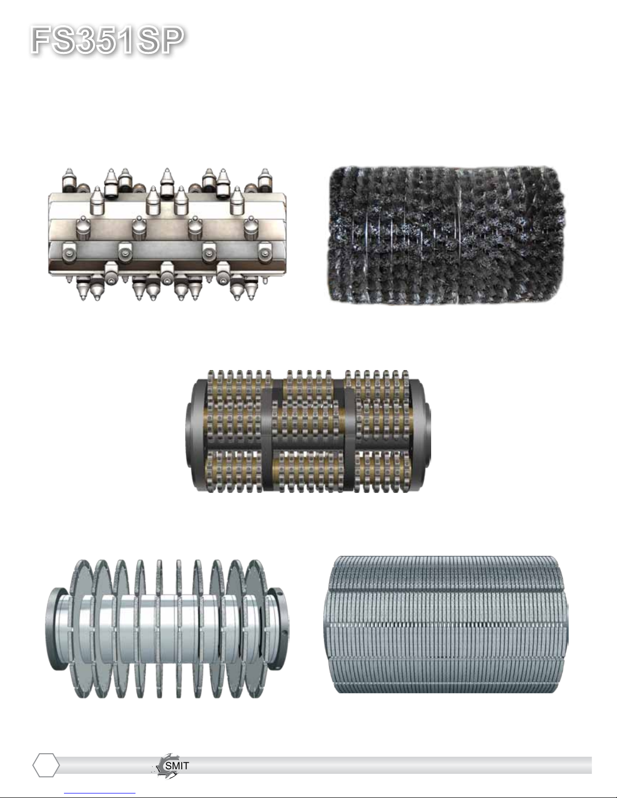
CUTTER DRUM OPTIONS
SMITH Cutter Drums are custom built to suit your specic needs. Below are some common examples.
Be sure to contact your SMITH Sales Representative for assistance with picking the drum options that are right
for your applications.
10 Blade Groove-It Drum
W.DB.FS350.10.25.32GA
45 Pick Plane-It Pick Drum
F350.PCK81.45GA
PLANE-IT CURE-IT
5-Shaft Guarantee-It Drum
F350.25.CF3001.15C
59 Blade Shave-It Drum
W.DB.FS350.10.25.15
Wire Brush Cure-It Drum
FS350.10.15.C
GROOVE-IT SHAVE-IT
GUARANTEE-IT

SMITH Manufacturing 1-954-941-9744 www.SmithMfg.com
SMITH Manufacturing 1-954-941-9744 www.SmithMfg.com
VERSION 11/2016
FS351SP
Propane
19
MAINTENANCE LOG

SMITH Manufacturing 1-954-941-9744 www.SmithMfg.com
FS351SP
VERSION 11/2016
Propane
20
SMITH Manufacturing 1-954-941-9744 www.SmithMfg.com
MAINTENANCE LOG
WARRANTY CLAIMS
The manufacturer reserves the right to change or improve the machine design without assuming any
obligation to update any products previously manufactured before this manual. It is the customer’s
responsibility to complete the warranty card and mail it to the seller within 10 days from the date
of purchase. If a failure occurs during the warranty period, the customer must contact the seller
to determine the appropriate action. Any and all transportation charges are to be borne by the
purchaser.
Table of contents
Other Smith Construction Equipment manuals


