Smith FS351 Series User manual

®
FS351 PCD Drum Assembly

Table of Contents
Component Identication............................................................................. page 3
Drum Assembly ............................................................................................ page 4
First Endcap Installation ................................................................ page 4
Plate Installation ............................................................................ page 4
Second Endcap Installation........................................................... page 5
Drum Installation .......................................................................................... page 6
Sideplate Removal......................................................................... page 6
Options for Handling/Lifting Drum................................................. page 7
First Hex Alignment ....................................................................... page 7
Second Hex Alignment.................................................................. page 8
Final Drum Assembly Onto Shaft .................................................. page 9
Sideplate Installation ..................................................................... page 9
SMITH Warranty ........................................................................................... page 10
2
WARNINGS
The following warnings are for the setup, use, grounding, maintenance, and repair of this equipment. The exclamation point symbol alerts you to
a general warning and the hazard symbols refer to procedure-specic risks. When these symbols appear in the body of this manual or on warning
labels, refer back to these Warnings. Product-specic hazard symbols and warnings not covered in this section may appear throughout the body
of this manual where applicable.
DUST AND DEBRIS HAZARD
Grinding concrete and other surfaces with this equipment can create dust that contains hazardous substances. Grinding can also create ying
debris.
To reduce the risk of serious injury:
• Control the dust to meet all applicable workplace regulations.
• Wear protective eye wear and a properly t-tested and government approved respirator suitable for the dust conditions.
• Use equipment only in a well-ventilated area.
• Grinding equipment must be used only by trained personnel who understand the applicable work-place regulations.
ENTANGLEMENT AND MOVING PARTS HAZARD
Moving parts can pinch, cut or amputate ngers and other body parts.
• Keep clear of moving parts.
• Do not operate equipment with protective guards or covers removed.
• Do not wear loose clothing, jewelry or long hair while operating equipment.
• Before checking, moving, or servicing equipment, disable power. For gas/propane units, disconnect negative (-) battery cable. For electric units,
unplug power cord.
BURN HAZARD
Cutters and engine can become very hot during operation. To avoid severe burns, do not touch hot equipment. Wait until equipment has cooled
completely.
PERSONAL PROTECTIVE EQUIPMENT
You must wear appropriate protective equipment when operating, servicing, or when in the operating area of the equipment to help protect you
from serious injury, including eye injury, inhalation of dust or chemicals, burns, and hearing loss. This equipment includes but is not limited to:
• Protective eye wear.
• Protective shoes.
• Gloves.
• Hearing protection.
• Properly t-tested and government approved respirator suitable for the dust conditions.
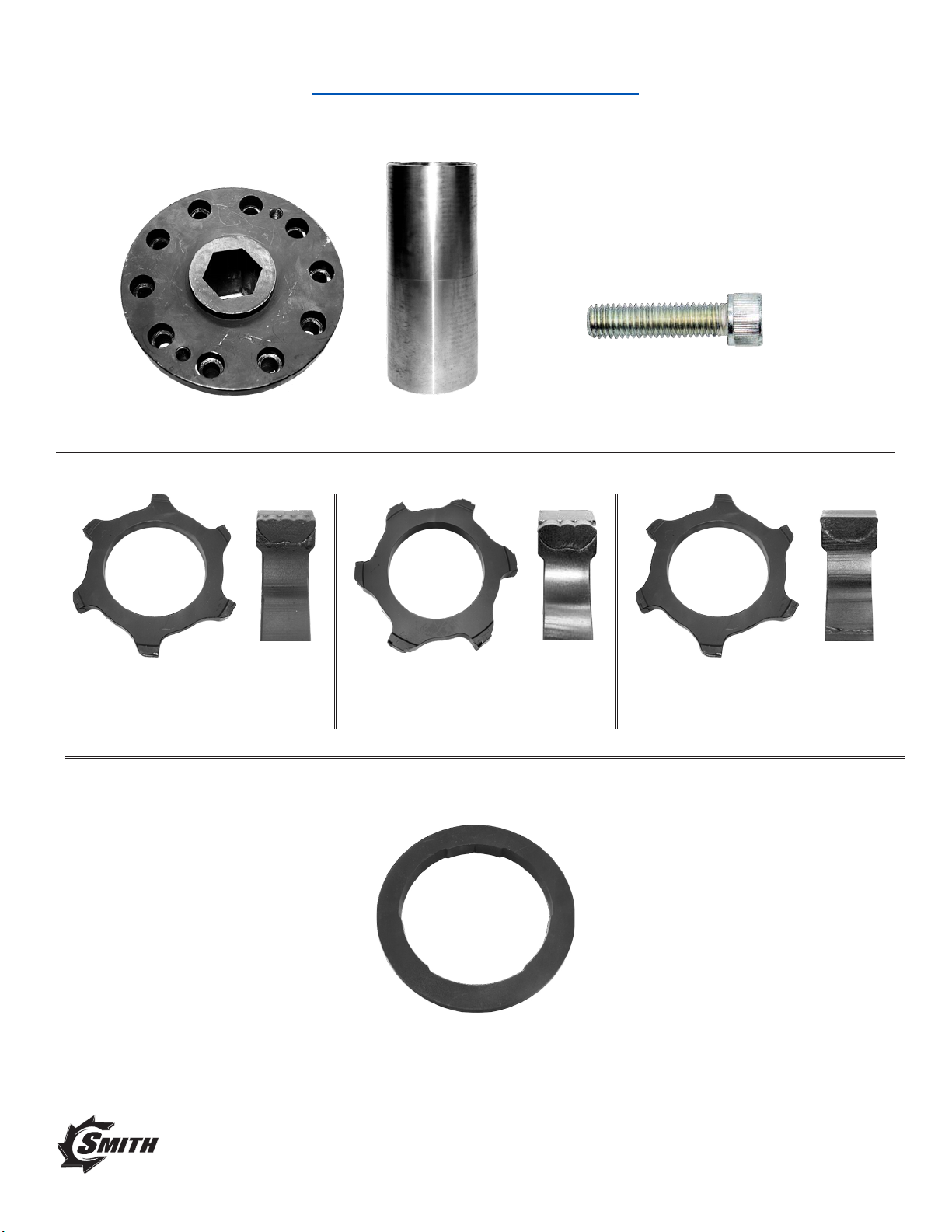
Component Identification
END CAP (QTY: 2) MANDREL (QTY: 1)
SOCKET HEAD BOLT – 3/8” ALLEN KEY
(HEX BIT) (QTY: 20)
PLATE – NANO-WAVE 10” OD
(QTY: 22 PLATES OR SPACERS)
SPACER – (USE AS A SUBSTITUTE FOR OTHER PLATES)
PLATE – ROUND 10” OD
(QTY: 22 PLATES OR SPACERS)
PLATE – FLAT 10” OD
(QTY: 22 PLATES OR SPACERS)
3
A GRACO COMPANY
™

4
Drum Assembly
First End Endcap Installation
• Place the endcap onto one end of the mandrel – ensure holes are aligned. Cleaning and light
polishing of surfaces may be required for proper t.
• Clean and apply blue threadlocker to the 10 hex head bolts, then insert each through the endcap
threading into the mandrel and hand-tighten in a star sequence (see below). Torque to 65 ft-lbs
(requires 3/8” hex bit socket).
Plate Installation
• Place mandrel on endcap end
• Ensure outside of mandrel and each plate are cleaned – light polishing of plate inside bore may
be required
• Gently align plate with mandrel (plate should be level and concentric force should not be re-
quired) remove plate and re-clean (do not use force, do not hammer, do not lubricate), then plate
should slip onto mandrel.

5
Plate Installation (cont’d)
• Place mandrel on endcap end.
• Ensure outside of mandrel and each plate are cleaned. A light polishing of plate inside bore may
be required.
• Gently align plate with mandrel (plate should be level and concentric force should not be re-
quired) remove plate and re-clean (do not use force, do not hammer, do not lubricate), then plate
should slip onto mandrel.
• Once plate is on mandrel, gently rotate the plate until it reaches the end cap.
Second Endcap Installation
• Insert the end cap onto the mandrel and insert two (2) hex cap bolts through the endcap into
the mandrel, then hand tighten. End cap installation for now is only for handling and moving the
drum. Final assembly of end cap will be after drum installation.
• One by one, slide each plate onto the mandrel ensuring all PCDs face the same direction. For
best performance, rotate each individual plate so that each blade is staggered.
Be sure to put all of the PCD plates facing the same direction,
otherwise severe damage to drum will occur.
Failure to properly assemble will result in voiding of warranty.
A GRACO COMPANY
™
6
Drum Installation
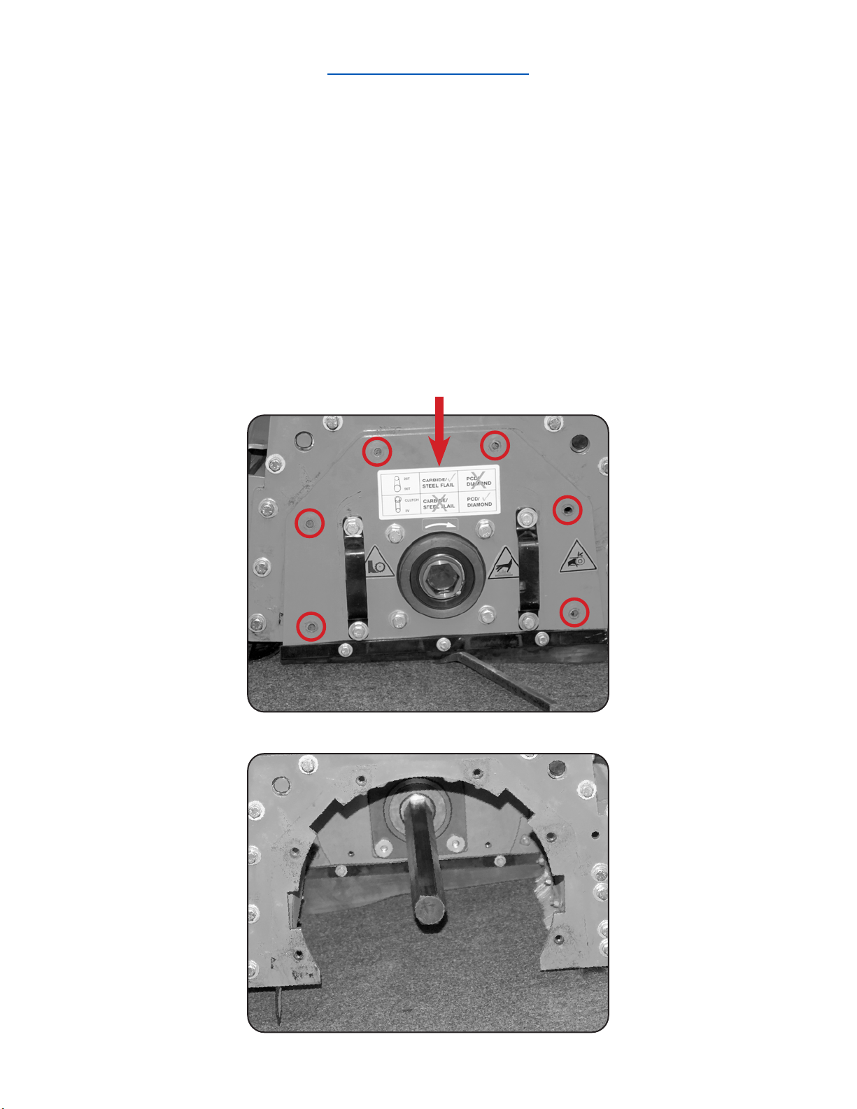
Sideplate Removal
• Remove the six (6) bolts and washers using a 9/16” socket – do not impact.
• Ensure the correct high-speed or clutch kit is installed.
• Remove side plate using handles, or gently pry.
• Remove existing drum and spacers if installed.
• Inspect shaft for any rounding or deformation.

7
Options For Handling and Lifting the Drum (Weighs up to 250lbs)
• Using the control box, or manually adjusting the actuator, simply raise and lower the machine
rather than the drum.
• Using lifting straps with an overhead crane, forklift, engine lift or other device to lift and move the
drum.
• Using a lift strap, use manpower to lift drum while additional person controls the drum.
• Using a skid plate or sheet of metal on the ground may allow you to drag or slide the drum.
First Hex Alignment
• Place drum on ground in front of hex shaft – look into main housing to see hex, then level hex
with drum
• Look through the hex at the other end of the drum, check hex level and alignment
• Lower and raise until hex is level, and rotate shaft until aligned with hex
• Slide drum straight onto hex shaft. Once aligned, there should be little resistance except
the weight of the drum. The drum will stop 3/4 of the way through. Do not force the shaft into
the drum.
37
A GRACO COMPANY
™

8
Second Hex Alignment
• Remove all of the bolts. Place two bolts into the endcap only (do not thread into the mandrel).
The mandrel and endcap should be able to rotate independently.
• Using a light source, peek into the hex bushing of the end cap and eyeball alignment with shaft.
• Lower or raise the machine as necessary.
• Rotate endcap using pry bar as shown below.
• Once the endcap hex is aligned with the shaft hex, the drum can be pushed onto the shaft.
37
9
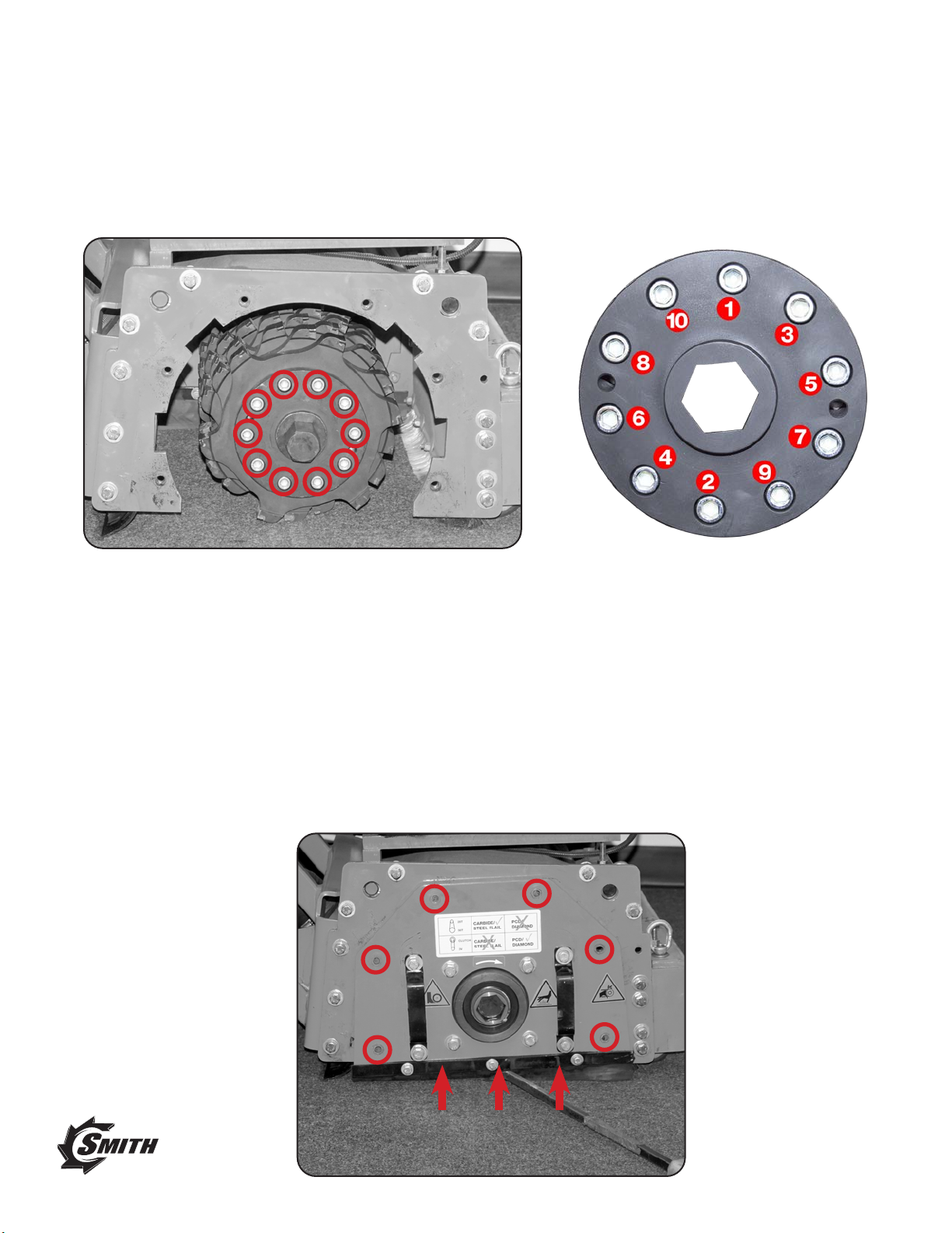
Final Drum Assembly Onto Shaft
• Clean and apply blue threadlocker to the ten (10) hex head bolts, then insert each through the
endcap threading into the mandrel. Hand-tighten in a star sequence (see below).
Torque to 65 ft-lbs (requires 3/8” hex bit socket).
Side Plate Installation
• Align hex shaft with sideplate bearing
• Using the handles, lift the sideplate into the main housing – the square notches must align.
NOTE: the weight of the drum can cause the shaft to sag and not align.
a) Raise/lower the machine using the actuator to level the shaft and allow the sideplate on
b) Using a pry bar, pry the sideplate off the oor into the housing
• Insert side plate bolts, tighten using a 9/16” socket. Torque to 40 ft-lbs, do not impact.
A GRACO COMPANY
™

SMITH Standard Warranty
SMITH warrants all equipment referenced in this document which is manufactured by SMITH and bearing its name to be
free from defects in material and workmanship on the date of sale to the original purchaser for use. With the exception of
any special, extended, or limited warranty published by SMITH, SMITH will, for a period of twelve months from the date
of sale, repair or replace any part of the equipment determined by SMITH to be defective. This warranty applies only
when the equipment is installed, operated and maintained in accordance with SMITH’s written recommendations.
This warranty does not cover, and SMITH shall not be liable for general wear and tear, or any malfunction, damage or
wear caused by faulty installation, misapplication, abrasion, corrosion, inadequate or improper maintenance, negligence,
accident, tampering, or substitution of non-SMITH component parts. Nor shall SMITH be liable for malfunction, damage
or wear caused by the incompatibility of SMITH equipment with structures, accessories, equipment or materials not sup-
plied by SMITH, or the improper design, manufacture, installation, operation or maintenance of structures, accessories,
equipment or materials not supplied by SMITH.
This warranty is conditioned upon the prepaid return of the equipment claimed to be defective to an authorized SMITH
distributor for verication of the claimed defect. If the claimed defect is veried, SMITH will repair or replace free of
charge any defective parts. The equipment will be returned to the original purchaser transportation prepaid. If inspection
of the equipment does not disclose any defect in material or workmanship, repairs will be made at a reasonable charge,
which charges may include the costs of parts, labor, and transportation.
THIS WARRANTY IS EXCLUSIVE, AND IS IN LIEU OF ANY OTHER WARRANTIES, EXPRESS OR IMPLIED, INCLUDING
BUT NOT LIMITED TO WARRANTY OF MERCHANTABILITY OR WARRANTY OF FITNESS FOR A PARTICULAR PUR-
POSE.
SMITH’s sole obligation and buyer’s sole remedy for any breach of warranty shall be as set forth above. The buyer
agrees that no other remedy (including, but not limited to, incidental or consequential damages for lost prots, lost sales,
injury to person or property, or any other incidental or consequential loss) shall be available. Any action for breach of
warranty must be brought within two (2) years of the date of sale.
SMITH MAKES NO WARRANTY, AND DISCLAIMS ALL IMPLIED WARRANTIES OF MERCHANTABILITY AND FITNESS
FOR A PARTICULAR PURPOSE, IN CONNECTION WITH ACCESSORIES, EQUIPMENT, MATERIALS OR COMPONENTS
SOLD BUT NOT MANUFACTURED BY SMITH. These items sold, but not manufactured by SMITH (such as electric
motors, switches, hose, etc.), are subject to the warranty, if any, of their manufacturer. SMITH will provide purchaser with
reasonable assistance in making any claim for breach of these warranties.
In no event will SMITH be liable for indirect, incidental, special or consequential damages resulting from SMITH supply-
ing equipment hereunder, or the furnishing, performance, or use of any products or other goods sold hereto, whether
due to a breach of contract, breach of warranty, the negligence of SMITH, or otherwise.
For SMITH Canadian Customers
The Parties acknowledge that they have required that the present document, as well as all documents, notices and
legal proceedings entered into, given or instituted pursuant hereto or relating directly or indirectly hereto, be drawn up
in English. Les parties reconnaissent avoir convenu que la rédaction du présente document sera en Anglais, ainsi que
tous documents, avis et procédures judiciaires exécutés, donnés ou intentés, à la suite de ou en rapport, directement ou
indirectement, avec les procédures concernées.
For the latest information about SMITH products, visit smithmfg.com.
TO PLACE AN ORDER, call 1-800-653-9311 for your SMITH sales representative.
All written and visual data contained in this document reects the latest product information available at the time of
publication. SMITH reserves the right to make changes at any time without notice.
Original instructions. This manual contains English. MM 3A7832
SMITH SURFACE-PREP SOLUTIONS • 2504 NW 19 ST • POMPANO BEACH, FL • USA
Copyright 2022, SMITH Manufacturing. www.smithmfg.com
Revision A, April 2022
Other manuals for FS351 Series
1
Table of contents
Other Smith Construction Equipment manuals


