WOOD'S POWR-GRIP MTCL6FS625DC User manual

KEEP FOR FUTURE REFERENCE
INSTRUCTIONS
International Version
MODEL NUMBER: __________
SERIAL NUMBER: __________
CLADDING LIFTER
DC-VOLTAGE
WITH DUAL VACUUM SYSTEM
AND VIFS625 PAD INSERTS
READ ALL INSTRUCTIONS AND WARNINGS
BEFORE OPERATING THIS LIFTER
DESIGNED FOR THE MATERIALS HANDLING PROFESSIONAL
P.O. Box 368 –908 West Main
Laurel, MT USA 59044
phone 800-548-7341
phone 406-628-8231
fax 406-628-8354

Rev 0.0/9-10 CLADDING LIFTER ● W/VIFS625 PAD INSERTS #35078:
1
SPECIFICATIONS
Model Number:
Description:
Power Source:
Battery Capacity:
Vacuum Pads:
MTCL6FS625DC
Designed for use with a crane or other hoisting equipment, the MTCL6FS625DC lifter employs
vacuum to hold a load for lifting, and it provides manual 90° tilt movements for load
manipulation.
12 volts DC, 26 amps
35 amp-hours
Six with nominal dimensions of 6½" x 25½" [17 cm x 65 cm] and closed cell EPDM foam
rubber inserts for applications on rough or textured surfaces (Model VIFS625), spring-mounted
(½" [12 mm] travel), with #60 filter screen
Pad Spread:1(to outer edges)
Minimum
Maximum w/o Extensions
Maximum w/Extensions
Length:
18¼" [464 mm]
117½" [2986 mm]
195¾" [4972 mm]
Width:
18¾" [479 mm]
56" [1420 mm]
56" [1420 mm]
Load Capacity:1
Per-Pad:
Maximum:
(rated at 16" Hg [-54kPa] on dry, clean, smooth, nonporous flat surfaces2)
150 lbs [68 kg]
700 lbs [320 kg] with 6 vacuum pads in use
Lifter Weight:
245 lbs [112 kg]
With Extensions:
360 lbs [164 kg]
Tilt Capability:
Manual, 90°; Latch engages automatically when pad frame reaches vertical or horizontal
position (if desired)
Dual Vacuum System:
2 vacuum system circuits allow the lifter to maintain the vacuum level in one circuit even if an
unexpected vacuum loss occurs in the other one (eg, due to load breakage).
Vacuum Pumps:
2 diaphragm type, 1 SCFM [28 liters/minute] nominal airflow
or
1 diaphragm type, 3 SCFM [85 liters/minute] nominal airflow
Vacuum Reserve Tanks:
2 vacuum reservoirs help prevent immediate vacuum loss in case of power failure and extend
battery life by reducing pump cycles required to maintain vacuum.
Vacuum Gauges:
2 dial gauges indicate current vacuum level in positive inches of Hg and negative kPa.
Vacuum Lift Lights:
2 green lights are energized whenever vacuum level is sufficient for lifting maximum load
weight (higher than 16" Hg [-54 kPa]).1
Low Vacuum Warning Buzzer:
1 audio buzzer is energized until vacuum level is sufficient to lift maximum load weight (higher
than 16" Hg [-54 kPa]).1
Options:
See appendix for instructions about optional features.
Operating Elevation:
Maximum = 6000 feet [1828 meters]
Operating Temperatures:
32° to 104° F [0° to 40° C]
Service Life:
This lifter is designed to have a service life of at least 20,000 lifting cycles, when used and
maintained as intended. Vacuum inserts, filter elements and other wear-out items are
excluded; see MAINTENANCE and REPLACEMENT PARTS LIST for more information.
ASME Standard BTH-1:
Design Category "B", Service Class "0" (see www.powrgrip.com for more information)
Wiring Diagram:
One or more wiring diagrams are provided in the final section of this
INSTRUCTIONS
manual
for reference when servicing the lifter or trouble-shooting a deficiency.
!!-CE-!! Note: This symbol appears in the
INSTRUCTIONS
manual only when requirements of a CE Standard are
different
from
requirements of other standards that also apply to this vacuum lifter. CE requirements are mandatory in geographical areas
where CE Standards apply, but may be optional in other locations.
1For a listing of Pad Spread and Maximum Load Capacity for all pad frame configurations, see the illustration under ASSEMBLY:
TO CHANGE THE PAD FRAME CONFIGURATION.
2Load Capacity is based on a friction coefficient of 1; see MAINTENANCE: VACUUM PAD MAINTENANCE: Friction Coefficient for
additional information.

Rev 0.0/9-10 CLADDING LIFTER ● W/VIFS625 PAD INSERTS #35078:
2
WARNINGS
Powr-Grip is pleased to offer the most reliable vacuum lifters available.
Despite the high degree of security provided by this product, certain
precautions must be observed to protect the operator and others.
Always
wear personal protective equipment that is appropriate for the material being handled.
Follow trade association guidelines.
Always
operate the lifter under conditions approved for its design (see INTENDED USE:
OPERATING ENVIRONMENT).
Never
operate a lifter that is damaged, malfunctioning, or missing parts.
Never
operate a lifter if the sealing edge of any vacuum pad is cut or otherwise damaged.
Never
remove or obscure warning labels.
Never
operate a lifter if the Load Capacity or any warning appears to be missing or obscured.
Always
make certain the contact surfaces of the load and all vacuum pads are clean prior to
applying the pads (see MAINTENANCE: VACUUM PAD MAINTENANCE).
Never
exceed the Load Capacity or attempt to lift loads the lifter is not designed for (see
INTENDED USE: LOAD CHARACTERISTICS).
Never
attempt to lift damaged panels with this lifter.
Always
position the vacuum pads correctly on the load prior to lifting (see OPERATION: TO APPLY
THE PADS TO A LOAD).
Never
lift a load when any vacuum indicator shows inadequate vacuum.
Never
touch the vacuum release controls during a lift. This may result in loss of vacuum and
release of the load.
Never
allow people to ride on the lifter or the load being lifted.
Never
lift a load higher than necessary or leave suspended loads unattended.
Never
lift a load over people.
Always
keep other personnel far enough away from the lifter to avoid injury in the event of an
unexpected load release.
Always
place the power control in the inactive position and, when possible, disconnect the
power source before opening any enclosure on the lifter. (Only applicable to powered lifters)
Always
remember that modifications to the lifter may compromise its safety. Wood’s Powr-Grip
Always
ensure that pad seals are kept clean and dry.
Note: It is the responsibility of the user to test the material to be lifted. Woods / GGR Group do
not accept any liability for damage and marking to material.
cannot be responsible for the safety of a lifter that has been modified by the customer. For
consultation, contact Wood's Powr-Grip.

Rev 0.0/9-10 CLADDING LIFTER ● W/VIFS625 PAD INSERTS #35078:
3
OPERATING FEATURES
Note: Components featured in the following instructions for assembling, operating or
maintaining the vacuum lifter are underlined on their first appearance in each section.
Standard MTCL6FS625DC shown without pad frame extensions.
1 ADJUSTABLE LIFT POINT TUBE
9 ENCLOSURE LATCH
17 BATTERY GAUGE
25 VACUUM CONTROL SWITCH
2 LIFT BAR
10 VACUUM PAD
18 BATTERY TEST BUTTON
26 POWER SYSTEM ENCLOSURE, with:
3 TILT DAMPER
11 PAD MOUNT
19 POWER LIGHT
VACUUM PUMP(S)
4 TILT CONTROL LEVER
12 CONTROL HANDLE
20 CHARGER CORD RECEPTACLE
VACUUM SWITCHES
5 PAD FRAME
13 QUICK CONNECTORS
21 POWER SWITCH
BATTERY
6 LIFT BAIL
14 TILT LATCH
22 CIRCUIT BREAKER
BATTERY CHARGER
7 VACUUM LIFT LIGHT
15 VACUUM GAUGE
23 CONTROLS RECEPTACLE
27 MOVABLE CONTROL PENDANT
8 LOW VACUUM WARNING BUZZER
16 AIR FILTER
24 VACUUM RELEASE BUTTON
PAD FRAME EXTENSIONS (not shown)

Rev 0.0/9-10 CLADDING LIFTER ● W/VIFS625 PAD INSERTS #35078:
4
ASSEMBLY
TO SET UP THE LIFTER
1) Open the shipping container and remove all materials for restraining or protecting the vacuum
lifter during shipping. Save the container for use whenever the lifter is transported.
2) Position the adjustable lift point tube as follows: The location of the lift point can be adjusted
to obtain the optimal hang angle of the lifter and load. A different hang angle may be
desirable, depending on the angle needed to attach the lifter to the load, release the load or
manipulate the load during a lift.
First disengage the lifter’s tilt latches (see OPERATION: TO TILT THE LOAD: Operating the Tilt
Latches) and raise the lift bar to a vertical orientation.
Make sure the lift bar latches in
the vertical orientation before releasing the lift bar.
To adjust the lift point location, remove both retaining bolts and associated hardware, and
reposition the adjustable lift point tube as desired. Reinstall the retaining bolts and hardware,
making sure to secure them tightly in position as originally installed.
WARNING: Lift point must be adjusted so as to prevent interference between
adjustable lift point tube and load.
Note: If the load would extend higher than the lift point when lifted or tilted upright (see
OPERATION: TO TILT THE LOAD), the lift point must be adjusted to prevent interference
between the adjustable lift point tube and the load. Failure to do so may damage the lifter or
load, and may result in the release of the load.
3) Suspend the lifter from a crane as follows: Select hoisting equipment (crane and hoist, when
applicable) rated to carry the maximum load weight plus the lifter weight (see
SPECIFICATIONS: Maximum Load Capacity and Lifter Weight).
Note: Any application of the lifter must conform to all statutory or regulatory standards that
relate to the hoisting equipment when used in its geographical location (eg, relevant OSHA
standards in the USA).
WARNING: Hoisting equipment hook must be fitted with restraining latch to
prevent lift bail from slipping off under any circumstances.
Attach the hoisting equipment hook to the lift bail, and use the hoisting equipment to raise
the lifter out of the shipping container. Be careful to avoid damaging any vacuum pads.
Note: Some hoisting equipment hooks could interfere with an upright load that extends
beyond the lifter’s pad frame. If the load would contact the hook during lifter operation, the
operator must prevent this by attaching a sling (or other rigging that does not interfere with
the load) between the hook and the lift bail.
WARNING: Any sling used must be rated to carry maximum load weight plus
lifter weight.

Rev 0.0/9-10 CLADDING LIFTER ● W/VIFS625 PAD INSERTS #35078:
5
4) Install the movable control pendant by inserting the plug of the coiled cord into the controls
receptacle on the power system enclosure. Then secure the connector by tightening its
threaded collar.
5) Assemble the pad frame in the configuration that will provide optimal support of the load
while lifting (see TO CHANGE THE PAD FRAME CONFIGURATION to follow).
6) Open the power system enclosure and connect the electrical connectors uniting the battery to
the battery charger and the vacuum generating system. Now the lifter is operational.
7) Perform Operational and Load Tests for the lifter as directed in MAINTENANCE: TESTING
SCHEDULE.
TO CHANGE THE PAD FRAME CONFIGURATION
This lifter offers a variety of pad frame configurations to accommodate different load dimensions
and weights (see illustrations on following page). Configurations are created by positioning,
rotating or removing the pad mounts, and/or by installing or removing pad frame extensions.
Always arrange the vacuum pads in a symmetrical configuration, in both width and length
dimensions.
CAUTION: Minimum of 2 vacuum pads must be mounted on main pad frame.
To prevent lifter damage and to provide adequate load support, a minimum of 2 activated
vacuum pads must be mounted on the main pad frame, regardless of the configuration selected
(see illustrations on following page). It is especially important to observe this rule when pad
frame extensions are employed: The vacuum pads may not be located solely on the extensions,
as such a configuration may not provide adequate load support and may damage the lifter.
The lifter is equipped with a dual vacuum system, as indicated by color-coded vacuum hoses.
For maximum effectiveness, adjacent vacuum pads must be connected to separate circuits of the
vacuum system in an even distribution. Make sure that an equal number of pads is connected to
the green circuit and to the red circuit.
After changing the pad frame configuration, make sure all vacuum hoses are secure and routed
to avoid being pinched, snagged, abraded or otherwise damaged while the lifter is in operation.
Also be sure to verify that all pads are connected and functioning correctly.

Rev 0.0/9-10 CLADDING LIFTER ● W/VIFS625 PAD INSERTS #35078:
6
Pad Spread and Maximum Load Capacity
(larger configurations shown with pad frame extensions)

Rev 0.0/9-10 CLADDING LIFTER ● W/VIFS625 PAD INSERTS #35078:
7
To Install/Remove Pad Frame Extensions
1) Insert the end of a pad frame extension in one socket on the
main pad frame, so that the holes align for the cotterless hitch
pin.
2) Secure the pad frame extension in the pad frame by pushing a
cotterless hitch pin through the holes until the retaining ball
emerges on the far side of the pad frame socket.
3) Use the quick connectors to connect the vacuum hoses from the pad frame extensions to the
main pad frame as directed in the discussion to follow.
3) Repeat steps 1-3 to install the other pad frame extensions as required for the pad frame
configuration desired.
4) To remove the pad frame extensions, reverse this procedure. Store pad frame extensions in
a clean, dry location to protect them from environmental exposure.
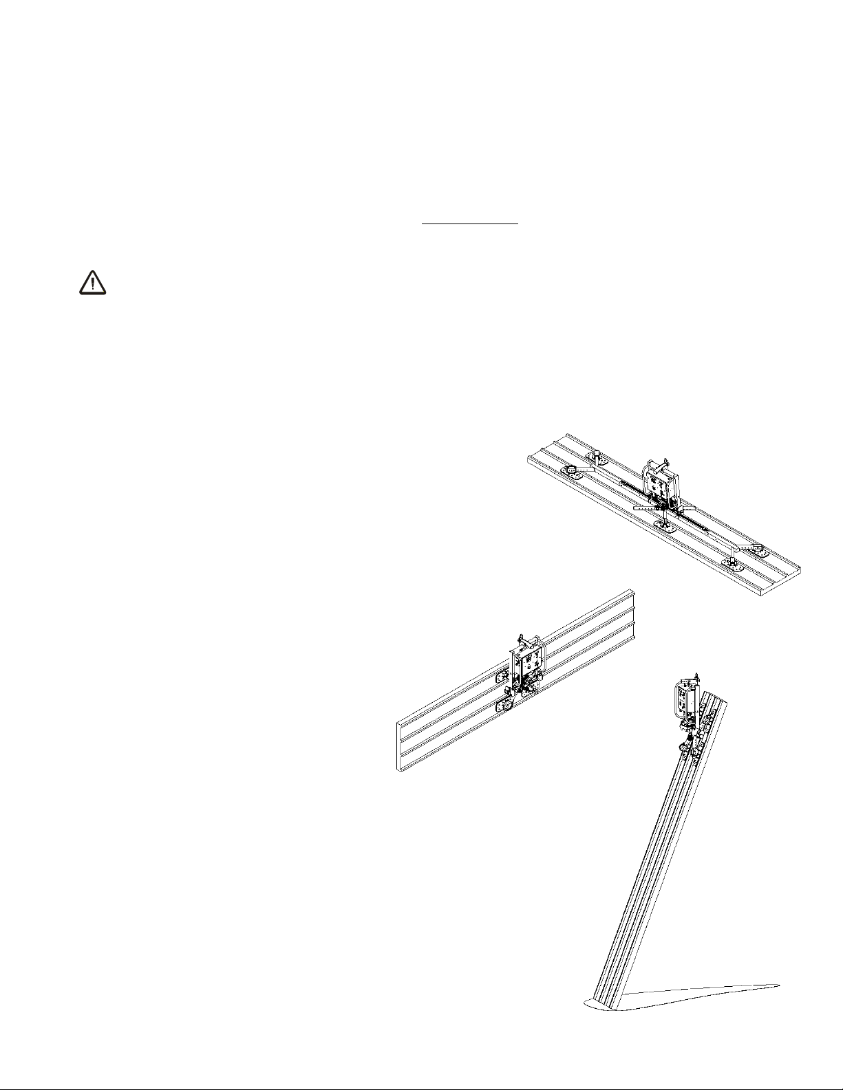
To Install/Remove, Rotate and Position Pad Mounts
1) Slide a pad mount over one arm of the pad frame. Note that the orientation of the vacuum
pad can be changed by moving the pad mount to an arm angled in a different direction. This
can be useful in avoiding obstacles or features on the load. Each pad mount can also be
rotated 180° to allow for the best hose routing.
2) Position the pad mount approximately in the desired position and line up one of the locating
holes in the pad mount with a corresponding hole in the pad frame arm. Multiple holes are
provided to accommodate small increments between mounting locations.
3) Use the quick connector to connect the vacuum hose from the vacuum pad to the appropriate
circuit of the vacuum system as directed in the discussion to follow.
4) Repeat steps 1-3 to install and position each vacuum pad as required for the pad frame
configuration desired.
5) To remove the pad mounts, reverse this procedure. Store pad mounts in a clean, dry location
to protect them from environmental exposure.
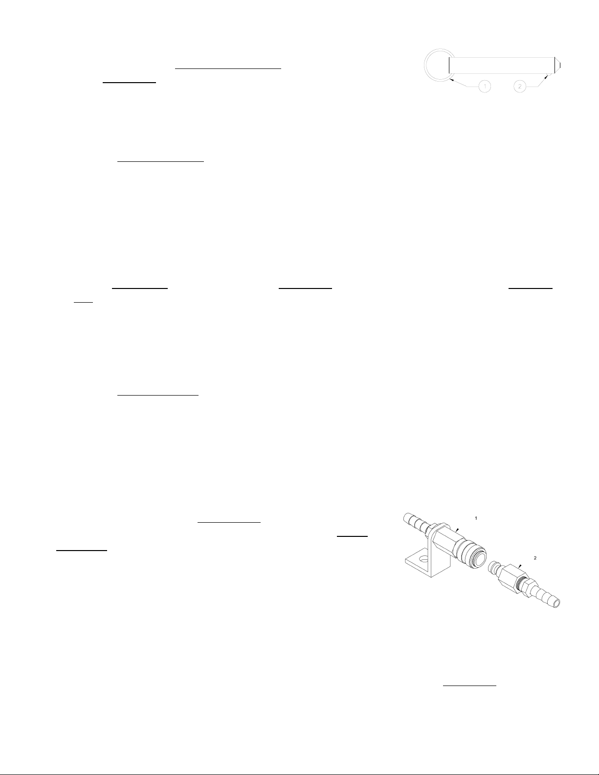
To Connect/Disconnect Vacuum Hoses
The vacuum hose for each vacuum pad is connected to or
disconnected from the vacuum system by means of a quick
connector. To connect the vacuum hose, push the male and
female ends of the connector together until they lock. To
disconnect the vacuum hose, move the release ring on the
female end away from the male end until the connector
separates.
Note: For proper function of the dual vacuum system, make sure
that vacuum pads are connected to alternating circuits of the
vacuum system (red or green).
Note: Whenever a quick connector is disconnected, the corresponding vacuum pad does not
contribute to the load capacity, whether or not the pad is mounted on the pad frame.
COTTERLESS HITCH PIN
1 PULL RING
2 RETAINING BALL
QUICK CONNECTOR
1) FEMALE END
2) MALE END

Rev 0.0/9-10 CLADDING LIFTER ● W/VIFS625 PAD INSERTS #35078:
8
INTENDED USE
LOAD CHARACTERISTICS
WARNING: This lifter is NOT intended for lifting hazardous materials, such as
explosives or radioactive substances.
The operator must verify that the lifter is intended to handle each load, in accordance with the
following requirements:
• The load must not exceed the maximum allowable weight specified under Load Capacity (see
SPECIFICATIONS).
• The load must be a single piece of nonporous or semiporous material with a flat and relatively
smooth contact surface. Lifters equipped with foam vacuum inserts are able to accommodate
surface relief up to 3/8" [9.5 mm], provided contour changes are not too abrupt. To
determine whether the load is too porous, rough or contoured to seal adequately, perform the
test under Vacuum Level on Other Surfaces (see OPERATION: TO APPLY THE PADS TO A LOAD).
• The load's contact surface must be suitable for obtaining a friction coefficient of 1 with the
lifter's vacuum pads (see MAINTENANCE: VACUUM PAD MAINTENANCE: Friction Coefficient), as
verified by a friction test. If necessary, contact Wood's Powr-Grip for help in conducting a
friction test.
•While the
minimum
length and width of the load are determined by the Pad Spread (see
SPECIFICATIONS), the
maximum
length and width are determined by the allowable
overhang, or the amount of load material that can extend sideways beyond the vacuum pads
without breaking or otherwise being damaged.
The allowable overhang depends on the kind of load material being lifted, the thickness of the
material, and the angle at which it is handled (if any). Since materials such as glass, stone or
sheet metal each have different physical properties, the allowable overhang must be
evaluated separately for each type of load. If necessary, contact Wood’s Powr-Grip or an
authorized dealer for help in determining the recommended overhang in a specific situation.
• 8" [20 cm] is the maximum allowable thickness of loads at the maximum weight (see
SPECIFICATIONS: Load Capacity). However, allowable thickness increases as load weight
decreases. If necessary, contact Wood’s Powr-Grip for help in determining the maximum
thickness permitted when handling any specific load.
Note: Vacuum pads can stain or deform load surfaces with light colors or soft coatings. The
operator should test such surfaces for detrimental effects before using the lifter on them.
OPERATING ENVIRONMENT
The operator must determine whether the lifter is intended to be used in each work environment,
in accordance with the following restrictions:
WARNING: Never use lifter in dangerous environments.

Rev 0.0/9-10 CLADDING LIFTER ● W/VIFS625 PAD INSERTS #35078:
9
• This lifter is not intended for use in any environment that is inherently dangerous to the
operator or likely to compromise the lifter's ability to function. Environments containing
explosives, caustic chemicals and other dangerous substances must be avoided when using
the lifter.
• The lifter's work environment is limited by the Operating Elevation and Operating Temperatures
indicated in SPECIFICATIONS.
• Using the lifter in wet environments may require the operator to take special precautions:
Moisture on contact surfaces of the load or vacuum pads diminishes the lifter’s slip resistance,
thereby reducing the lifting capacity (see MAINTENANCE: VACUUM PAD MAINTENANCE: Friction
Coefficient).
WARNING: Moisture reduces slip resistance of vacuum pads.
Although the lifter's exterior surfaces can tolerate some exposure to water vapor, they are not
designed to be water-tight. Submerging the lifter or using it in rain may damage lifter
components; these and similar conditions must be avoided.
TYPICAL APPLICATIONS
Though the lifter is designed with the
flexibility to be used in many different
ways, the following illustrations
represent some typical applications.

Rev 0.0/9-10 CLADDING LIFTER ● W/VIFS625 PAD INSERTS #35078:
10
OPERATION
BEFORE USING THE LIFTER
The operator must determine whether the lifter is capable of performing each intended task, in
accordance with the SPECIFICATIONS and INTENDED USE sections of this
INSTRUCTIONS
manual. In addition, all of the following preparations must be completed prior to lifting any load.
Taking Safety Precautions
The operator must read and understand this
INSTRUCTIONS
manual, including all
WARNINGS
,
before using the lifter. If necessary, contact Wood’s Powr-Grip or an authorized dealer for
assistance.
WARNING: Always wear appropriate personal protective equipment.
The operator must wear any personal protective equipment and take any other precautions
required to handle the load safely. Consult appropriate trade association guidelines to determine
what precautions are necessary for each type of load material.***
Performing Inspections and Tests
WARNING: Always check battery energy before using lifter.
(See MAINTENANCE: BATTERY TEST)
Perform all inspections and tests required by the INSPECTION and TESTING
SCHEDULES (see MAINTENANCE). In addition, if the lifter has been in storage,
always conduct a VACUUM TEST before placing it in service (see MAINTENANCE).
CAUTION: Examine each air filter regularly, and empty when necessary.
Two air filters help protect the vacuum generating system from contaminants. However, the
lifter is not intended for use on wet load surfaces because the filters would not necessarily
prevent liquid from entering the vacuum system. In order for a filter to function, the operator
must empty the filter bowl before enough liquid accumulates to contact any portion of the filter
element (see MAINTENANCE: AIR FILTER MAINTENANCE).
Confirming the Pad Frame Configuration
WARNING: Load Capacity of lifter varies, depending on pad frame configuration.
Make sure the pad frame has been assembled in the configuration that will provide optimal
support of the load while lifting (see ASSEMBLY: TO CHANGE THE PAD FRAME CONFIGURATION). The
pad frame configuration selected must be appropriate both for the weight and for the dimensions
of the load to be lifted.

Rev 0.0/9-10 CLADDING LIFTER ● W/VIFS625 PAD INSERTS #35078:
11
TO APPLY THE PADS TO A LOAD
Powering up the Lifter
Place the power switch in the "ON" position (power light remains illuminated while power is
engaged). The power switch must remain in the "ON" position while operating the lifter.3
WARNING: Never turn power off while operating lifter.
Placing the power switch in the "OFF" position during lifter operation could result in the release of
the load and possible injury to the operator (see TO LIFT AND MOVE THE LOAD: In Case of Power
Failure to follow).
Positioning the Lifter on the Load
Make certain that the contact surfaces of the load and all vacuum pads are free of any
contaminates that could prevent the pads from sealing against the load (see MAINTENANCE:
VACUUM PAD MAINTENANCE).
To lift loads in the
flat
orientation (see INTENDED USE: TYPICAL APPLICATIONS), center the pad
frame to within 2" [5 cm] of the load center (hereafter, "on center"), since off-center loading can
cause the load to hang at an angle or to tilt unexpectedly (see TO TILT THE LOAD to follow), and it
may also damage the lifter.4
To lift loads in the
upright
orientation (see INTENDED USE: TYPICAL APPLICATIONS), center the pad
frame from left to right on the load and determine which will be the top edge of the load while
lifting. Then position the vacuum pads near that edge (hereafter, "above center"). This position
will maximize stability while lifting the load.
WARNING: When lifter is positioned above center, tilt latches must be locked
out before lifting load.
If the lifter is positioned above center on a load encountered in the flat orientation, the load
automatically tilts to the upright position when lifted (see TO TILT THE LOAD: Tilting Loads
Positioned Above Center to follow). In this case, failure to lock out the tilt latches could result in
an unexpected load release or damage to the lifter.
Make sure that all vacuum pads will fit entirely on the load’s contact surface (see
SPECIFICATIONS: Pad Spread) and that they will be loaded evenly while lifting (see
SPECIFICATIONS: Per-Pad Load Capacity). Then apply the lifter to the load so that all pads are
touching the contact surface.
3If a vacuum pump or any other powered component fails to function while the power switch is in the "ON" position, examine
each circuit breaker (adjacent to power switch) to determine whether it has interrupted the electrical circuit to the component.
Although the operator can reset the circuit breaker, the power interruption may indicate an electrical problem that requires
attention. Correct any deficiency before resuming normal operation of the lifter (see wiring diagram provided).
4The lifter is designed to handle the maximum load weight (see SPECIFICATIONS: Maximum Load Capacity) when the load’s
center of gravity is positioned within 2" [5 cm] of the pad frame’s center point. Occasional loading deviations are permissible,
provided that the operator can maintain control of the load at all times and that the load weight is low enough to avoid damaging
the lifter.

Rev 0.0/9-10 CLADDING LIFTER ● W/VIFS625 PAD INSERTS #35078:
12
WARNING: Lift point must be adjusted so as to prevent interference between
adjustable lift point tube and load.
Note: If the load would extend higher than the lift point when lifted or tilted upright, the lift
point must be adjusted to prevent interference between the adjustable lift point tube and the
load (see ASSEMBLY: TO SET UP THE LIFTER). Failure to do so could damage the lifter or load, and
may result in an unexpected load release.
Sealing the Pads against the Load
The vacuum control switch is located on the movable control pendant. The movable control
pendant allows the vacuum controls to be moved away from the lifter, so that the operator can
control airflow at a distance equal to the length of the extension cord.
Turn the vacuum control switch to the “APPLY” position (clockwise). This engages the vacuum
pumps, causing air to be drawn immediately at the vacuum pads. Press the lifter onto the load
until all the pads seal against it. The vacuum control switch must remain in the “APPLY” position
throughout the entire lift.
WARNING: Keep vacuum control switch in “APPLY” position throughout lift.
Note: If a vacuum pad has been lying against a hard object (as during shipping), it may be
slightly distorted. Although initially it may be difficult to apply the pad to a load, this condition
should correct itself with continued use.
Reading the Vacuum Gauges
The lifter is equipped with 2 vacuum gauges, which indicate the current vacuum level in each
circuit of the lifter's vacuum system. The
green
range indicates vacuum levels sufficient for
lifting the maximum load weight, whereas the
red
range indicates vacuum levels that are
not
sufficient for lifting the maximum load weight. The gauge needles should show a sudden surge
in vacuum as the vacuum pads seal against the load. If it takes more than 5 seconds for the
vacuum level to reach 5" Hg [-17 kPa] on a vacuum gauge, press on any pad that has not yet
sealed.

Rev 0.0/9-10 CLADDING LIFTER ● W/VIFS625 PAD INSERTS #35078:
13
Vacuum Level on Optimal Surfaces
When the lifter is attached to clean, smooth, nonporous load surfaces, it should be able to
maintain a vacuum level in the green range on both vacuum gauges, except when used at high
elevations (see SPECIFICATIONS: Operating Elevation). If not, make sure the vacuum switches
are adjusted correctly (see MAINTENANCE: VACUUM SWITCH ADJUSTMENT). If the vacuum switches
cannot be adjusted to maintain a vacuum of 16" Hg [-54 kPa], perform the VACUUM TEST (see
MAINTENANCE) to determine whether there is a deficiency in the vacuum generating system.
Vacuum Level on Other Surfaces
When the lifter is attached to contaminated, rough or porous load surfaces, it may not be able to
maintain a vacuum level in the green range on both vacuum gauges, due to leakage in the seal
between the vacuum pads and the load surface.5In the case of contamination, thoroughly clean
the contact surfaces of the load and the vacuum pads (see MAINTENANCE: VACUUM PAD
MAINTENANCE: Cleaning), and reapply the lifter to the load. If the load has rough or porous
surfaces,
the operator must conduct a test to determine whether the lifter is designed
to lift the load
, as follows:
1) Make sure the lifter's vacuum generating system is functioning correctly (see MAINTENANCE:
VACUUM TEST).
2) Apply the vacuum pads to the load as previously directed.
3) After the vacuum pumps stop running, place the power switch in the "OFF" position.
4) Raise the load a minimal distance, to assure that it is supported by the lifter.
5) Monitor both vacuum gauges while the load is suspended for 5 minutes:
The lifter must
maintain a minimum vacuum level of 10" Hg [-34 kPa] during this time.
If not, the
load does not possess the characteristics required for using this lifter.6
5Contaminated loads can also cause the vacuum pumps to run frequently or continuously. Since excessive pumping quickly
reduces battery energy, the operator should clean the load when possible, to minimize pumping.
6Certain load materials are too rough or porous to allow the lifter to form a seal which can be maintained for 5 minutes without
power. However, in geographical locations where CE Standards do not apply, it may be possible to use the lifter to lift such loads.
Contact Wood’s Powr-Grip for more information.

Rev 0.0/9-10 CLADDING LIFTER ● W/VIFS625 PAD INSERTS #35078:
14
TO LIFT AND MOVE THE LOAD
Positioning the Lift Bar
WARNING: Lift bar must be oriented vertically to lift load.
Never lift the load from a flat position with the lift bar latched parallel
to the load. Always disengage the tilt latches (see TO TILT THE LOADto
follow) and raise the lift bar to a vertical orientation before attempting
to lift.
Load Capacity and the Lift Light
A lifter’s Load Capacity is rated at a vacuum level of 16" Hg [-54 kPa] (see SPECIFICATIONS).
After the lifter has attained this level, the low vacuum warning buzzer turns off automatically and
at the same time, the vacuum lift light turns on, to indicate that the lifter is ready to lift the
maximum load weight. At a level slightly above 16" Hg [-54 kPa], the vacuum pumps turn off to
conserve battery energy.
WARNING: Never attempt to lift load unless green lift light is illuminated.
Do not attempt to lift the load unless the lift light is illuminated; such an attempt could result in a
load release and possible injury to the operator.
Monitoring Vacuum Indicators
The vacuum lift light and both vacuum gauges must remain completely visible to the operator, so
that they can be monitored throughout the entire lift.
WARNING: Vacuum indicators must be visible to operator throughout entire lift.
If the vacuum system experiences leakage while the lifter is attached to the load, the vacuum
pumps turn
on
automatically, as required to maintain sufficient vacuum for lifting the maximum
load weight. The lift light remains illuminated unless the pumps are unable to maintain adequate
vacuum. In that case, the lift light turns
off
and the low vacuum warning buzzer sounds, to
signal the reduction in vacuum to the operator.
If the lift light turns off and the buzzer sounds while you are lifting a load, move away and stay
clear of the load until it can be lowered to the ground or a stable support.
WARNING: Stay clear of any suspended load while buzzer sounds.
Discontinue lifter use until the cause of the vacuum loss can be determined. If the pumps run at
intervals of five minutes or less while the lifter is attached to clean, smooth, nonporous materials,
a leak in the vacuum system is likely to be the cause. In this event, perform the VACUUM TEST
(see MAINTENANCE) and inspect the vacuum pads for damage (see MAINTENANCE: VACUUM PAD
MAINTENANCE: Inspection). If the vacuum loss cannot be remedied immediately, perform
inspection and maintenance as needed to identify and correct any deficiency before resuming
normal operation of the lifter.

Rev 0.0/9-10 CLADDING LIFTER ● W/VIFS625 PAD INSERTS #35078:
15
Controlling the Lifter and Load
When vacuum indicators show that the lifter is ready, use the hoisting equipment to raise the
lifter and load as needed to clear any obstacles in their path. Use the control handles or other
appropriate means to keep the lifter and load in the desired orientation while they are suspended
from the crane.
WARNING: When lifter is positioned above center, tilt latches must be locked
out before lifting load.
If the lifter is positioned
above center
on a load encountered in the flat orientation, the load
automatically tilts to the upright position when lifted (see TO TILT THE LOAD: Tilting Loads
Positioned Above Center to follow). In this case, failure to lock out the tilt latches could result in
an unexpected load release or damage to the lifter. If the load is positioned
on center
, the load
can be tilted as desired once sufficient clearance is established (see TO TILT THE LOAD: Tilting
Loads Positioned On Center to follow).
In Case of Power Failure
The lifter is equipped with 2 vacuum reserve tanks, designed to maintain vacuum temporarily in
case of a failure at the lifter's power source.
WARNING: Stay clear of any suspended load in the event of a power failure.
Although the lifter is designed to support the load for at least 5 minutes without power, this
depends on many factors, including the condition of the load and the lifter’s vacuum system (see
INTENDED USE: LOAD CHARACTERISTICS and MAINTENANCE: VACUUM PAD MAINTENANCE,VACUUM
TEST). If a power failure occurs, keep all personnel clear of the suspended load until it can safely
be placed on the ground or a stable support. Correct any deficiency before resuming normal
operation of the lifter.

Rev 0.0/9-10 CLADDING LIFTER ● W/VIFS625 PAD INSERTS #35078:
16
TO TILT THE LOAD
WARNING: Make sure load is positioned correctly on lifter (see TO APPLY);
unbalanced loads may tilt unexpectedly when latches are
disengaged.
The tilt feature allows the operator to transfer a load from the flat position to the upright
position, and vice versa (see INTENDED USE: TYPICAL APPLICATIONS). Remember that the load
requires more vertical space when tilting to the upright position, as well as more horizontal space
when tilting to the flat position. Make sure there is sufficient clearance for the load to tilt without
contacting the operator or any nearby objects. Keep the load under control throughout the tilt
using control handles, control lines or other appropriate means.
The appropriate way to tilt the load differs, depending on whether the lifter is attached to the
load "above center" or "on center" (see To Apply the Pads to the Load: Positioning the Lifter on
the Load preceding), as follows:
Tilting Loads When Lifter is Positioned
Above Center
WARNING: When lifter is positioned above center, tilt latches must be locked
out before lifting load.
The tilt latches must always be locked out when the lifter is positioned above center (see
Operating the Tilt Latches to follow). Failure to lock out the tilt latches could result in an
unexpected load release or damage to the lifter and load.
If the lifter is positioned above center on the load, the load automatically tilts from the flat
position to the upright position when lifted. To tilt the load from the upright position to the flat
position, use the hoisting equipment to lower the load until its lower edge is adequately
supported. Then move the lifter forward and downward, allowing the load to tilt to the flat
orientation as you continue to lower it.
Tilting Loads When Lifter is Positioned
On Center
If the lifter is positioned on center, disengage the tilt latches (see Operating the Tilt Latches to
follow) and prepare for a slight surge of motion as the load begins to tilt. Lift upward or press
downward on the control handles to tilt the load as desired, and continue to apply pressure as
necessary to maintain the desired load orientation.
If load size permits, maintain control with the handles throughout the tilt. For loads with
overhang, it may be necessary to release the control handles as a load approaches the flat
position. If so, keep the load under control using hand cups or other appropriate means.
Operating the Tilt Latches
To disengage the tilt latches, push the tilt control lever
part of the way
upward. The pad frame
automatically latches in place when the load reaches either the upright or the flat position,
provided that you release the control lever after the tilt motion has been initiated. However,
automatic latching can be defeated by continuing to hold the control lever so that the tilt latches
do not engage. Alternatively, you can lock out the tilt latches, so that they will not engage at any
time during the tilt: To lock out the tilt latches, push the tilt control lever
all the way
upward
until it locks in the disengaged position. Whenever tilt is not required, keep the tilt latches
engaged, to prevent accidental damage to the load and possible injury to the operator.

Rev 0.0/9-10 CLADDING LIFTER ● W/VIFS625 PAD INSERTS #35078:
17
TO RELEASE THE PADS FROM THE LOAD
WARNING: Load must be fully supported before releasing vacuum pads.
Make sure the load is at rest and fully supported. As an additional safety precaution, two actions
must be performed to release the vacuum pads from the load: Press the vacuum release button
and, at the same time, turn the vacuum control switch to the “RELEASE” position (counter-
clockwise) to force air into the pads, quickly breaking the vacuum seal. Continue to hold the
vacuum control switch until the pads disengage completely from the load.
About Stand-By Mode
When the vacuum control switch is no longer held in the “RELEASE” position, it automatically
returns to the neutral position. Do not turn the vacuum control switch to the “APPLY” position
until the pads are contacting the next load to be lifted. This conserves battery energy and
reduces the time required to apply the pads to the load, by preventing the vacuum reserve tanks
from losing their vacuum.
AFTER USING THE LIFTER
Leave the vacuum control switch in the neutral position and place the power switch in the “OFF”
position (power light shuts off when power is disengaged).
CAUTION: Do not set the lifter against any surfaces which could soil or damage the
vacuum pads.
To remove the lifter from the hoisting equipment, place stable supports under the center of the
pad frame. Additional supports may be placed under the pad frame extensions for stability. Use
the hoisting equipment to gently lower the lifter until the supports are holding its entire weight.
Make sure the lifter is stable; then detach the hoisting equipment hook from the lift bail.
If the lifter is transported to another location, use the original shipping container and secure the
lifter so as to protect the vacuum pads and all other components from damage while in transit.
Storing the Lifter
Charge the battery completely when placing it in storage and at six-month intervals thereafter
(see MAINTENANCE: BATTERY RECHARGE). After charging the battery, open the power system
enclosure and disconnect the electrical connector uniting the battery charger and the battery, in
order to prevent power drainage. Disconnecting the battery from the vacuum generating system
is also recommended.7Preferred temperatures for storing the battery are 32° to 70° Fahrenheit
[0° to 21° Celsius]. Higher temperatures require the battery to be charged more frequently.
Storage at temperatures above 100° Fahrenheit [38° Celsius] should be avoided.
7Place the power switch in the "OFF" position before disconnecting the battery leads.

Rev 0.0/9-10 CLADDING LIFTER ● W/VIFS625 PAD INSERTS #35078:
18
MAINTENANCE
WARNING: Always make sure battery is disconnected before servicing lifter.
INSPECTION SCHEDULE
Perform inspections routinely, according to the following frequency schedule:
Every-Lift Inspection
• Examine the vacuum pads and load surface for contamination or debris (see VACUUM PAD
MAINTENANCE to follow).
• Examine the vacuum pads, controls and indicators for visual damage (see VACUUM PAD
MAINTENANCE to follow).
• Test the battery for adequate charge (see BATTERY TEST to follow).
If a battery’s charge appears to be inadequate, charge and retest the battery (see BATTERY
RECHARGE to follow). If any other deficiency is detected during the inspection, correct it before
using the lifter and perform the Frequent Inspection to follow.
Frequent Inspection
(
following every 20-40 hours’ use; or whenever lifter is out of service for 1 month or more
)
• Examine the lifter’s structure for visual damage.
• Examine the vacuum system (including vacuum pads, fittings and hoses) for visual damage.
• Examine the air filters for conditions requiring service (see AIR FILTER MAINTENANCE to follow).
• Perform the VACUUM TEST to follow.
• Check for unusual vibrations or noises while operating the lifter.
If any deficiency is detected during the inspection, correct it before using the lifter and perform
the Periodic Inspection to follow.
Periodic Inspection
(
following every 250-500 hours’ use; or whenever lifter is out of service for 1 year or more
)
• Examine the entire lifter for external evidence of looseness, excessive wear, deformation,
cracks, excessive corrosion, dents to structural or functional components, cuts, or any
deficiency which might constitute a hazard.
• Keep a written record of all Periodic Inspections.
If any deficiency is detected during the inspection, return the lifter to Wood’s Powr-Grip or an
authorized dealer for repair (see LIMITED WARRANTY).
Infrequent Use
If a lifter is used less than 1 day in a 2-week period, perform the Periodic Inspection
each time
before using the lifter
.

Rev 0.0/9-10 CLADDING LIFTER ● W/VIFS625 PAD INSERTS #35078:
19
TESTING SCHEDULE
Perform these tests when placing the lifter in service
initially
and
each time following a repair or
modification
. Correct any deficiency and retest before using the lifter.
Operational Tests
• Perform the VACUUM TEST to follow.
• Test all features and functions of the lifter (see OPERATING FEATURES, OPERATION and
MAINTENANCE).
Load Test
Prove that the lifter can lift 100% of its Maximum Load Capacity (see SPECIFICATIONS), using an
actual load or an equivalent simulation.8Employ the following method to test with an actual
load:
1) Place a test load with appropriate LOAD CHARACTERISTICS (see INTENDED USE) on a stable
support. Make sure the load is oriented in the upright position.
2) Apply the vacuum pads to the load as previously directed.
3) After the vacuum pumps stop running, place the power switch in the "OFF" position.
4) Raise the load a minimal distance, to assure that it is supported by the lifter.
5) Hold the load for 5 minutes. The load must not slip or fall during this time period. If it does,
conduct a VACUUM TEST and inspect each vacuum pad as indicated under VACUUM PAD
MAINTENANCE: Inspection (see sections to follow). Correct any deficiency that is found and
retest the lifter.
Note: See MAINTENANCE topics to follow for additional directions about inspecting and testing
specific lifter components.
MAINTENANCE SCHEDULE
Unless specified elsewhere in this
INSTRUCTIONS
manual, the lifter does not require
maintenance on a routine basis. Instead, maintenance must be performed whenever a
deficiency is indicated by routine inspections or tests. Any maintenance warranted must be
performed before resuming normal operation of the lifter.
8ASME Standard B30.20 requires the lifter to be tested to 125% of its Load Capacity.
Table of contents
Other WOOD'S POWR-GRIP Construction Equipment manuals