Smith Newton 2000 Series User manual


Page | 2 © 2012 Smith Electric Vehicles CD-0650-0018r0
This Page Intentionally Left Blank

© 2012 Smith Electric Vehicles CD-0650-0018r0 Page | 3
SECTION PAGE
1. Introduction................................................................................................................. 5
2. Safety Notices and Instructions.................................................................................. 7
3. Vehicle Layout............................................................................................................ 9
4. Controls and Display ................................................................................................ 11
5. Charging HV and 24V Systems................................................................................ 15
6. Pre-Start Checks...................................................................................................... 21
7. Driving the Vehicle.................................................................................................... 23
8. Cabin Temperature Control...................................................................................... 25
9. Parking the Vehicle................................................................................................... 27
10. Maintenance........................................................................................................... 29
11. Towing Procedure .................................................................................................. 35
12. Fault Finding Matrix................................................................................................ 37
Table of Contents

Page | 4 © 2012 Smith Electric Vehicles CD-0650-0018r0
This Page Intentionally Left Blank

© 2012 Smith Electric Vehicles CD-0650-0018r0 Page | 5
All information contained in this manual is based on the latest product information available
at the time of printing. We reserve the right to make changes at any time without notice. No
part of this publication may be reproduced or transmitted, in any form by any means,
including electronic, mechanical, photocopying, recording or otherwise, without the prior
written permission of the publisher. This includes text, pictures and tables.
This manual has been produced and is intended as a complement to the Avia Ashok Leyland
Motors Original Owners Manual (Avia Manual). To become familiar with the vehicle, it is
necessary to read and understand this manual, the Avia Manual and all additional literature
that is part of your vehicle’s documentation pack (e.g. Owner’s manuals for Tail lift, Radio
and Back-Up camera, etc.).
It is your responsibility to ensure that all the documentation stays with the vehicle and is fully
read and understood by anyone operating or otherwise maintaining the vehicle.
To ensure you are fully aware of safety and operational information, the following symbols
are used throughout this manual.
NOTICE
Indicates a situation not related to personal injury.
WARNING
Indicates a hazardous situation which, if not avoided, could result in
death or serious injury.
CAUTION
Indicates a hazardous situation which, if not avoided, could result in
minor or moderate injury.
1. Introduction

Page | 6 © 2012 Smith Electric Vehicles CD-0650-0018r0
This Page Intentionally Left Blank

© 2012 Smith Electric Vehicles CD-0650-0018r0 Page | 7
High Voltage Isolator
Figure 2.1
WARNING
Never attempt to open a battery pack. This vehicle uses a battery pack that
operates at 320 volts DC.
WARNING
Never attempt to remove, unplug or cut any of the ORANGE marked
cables or conduit. Orange marked cables carry high voltage.
WARNING
Only authorized personnel are allowed to work on the electrical power
and/or control systems.
CAUTION
DO NOT perform any welding work on the vehicle without permission
from Smith Electric Vehicles. Serious damage can be caused to the drive
train and the electronic control systems.
CAUTION
Hazardous Location Warning: It may not be appropriate to operate this
electric vehicle in special occupancies, classified locations, or hazardous
locations as defined by the National Electrical Code, Section 1.
CAUTION
EMF/EMR WARNING: Potential electromagnetic field or electromagnetic
charge around this electrical vehicle may impact medical electronic devices.
2. Safety Notices and Instructions
The vehicle is fitted with a High Voltage Isolator that removes the
power to the controller. This isolator, located between the seats
on the control panel (Figure 2.1), should be activated in the event
of a vehicular accident.
Do not reset the High Voltage Isolator until the emergency
situation has passed. The High Voltage Isolator is 'reset' by
returning the red switch cover to the RUN position i.e. covering
the switch, and re-starting the vehicle in the normal manner.
Do not operate the High Voltage Isolator while the vehicle is
in motion! If the High Voltage Isolator is activated when the
vehicle is in motion, the steering will become stiff and the vehicle
will continue to roll. The regenerative braking system will not
assist braking. The service brake will operate until air is depleted,
then a safety mechanism will automatically apply the rear brakes.
This automatic braking cannot be driver controlled and the brake
will remain on until air system is charged.
Refer to Smith Electric Vehicles Process Document CD-0650-0010 for
detailed First Responder Instructions.

Page | 8 © 2012 Smith Electric Vehicles CD-0650-0018r0
If this vehicle is involved in an accident:
1. Activate High Voltage Isolator. (Figure 2.1)
2. Remove the ignition key.
3. Exit cab and turn the 24V System Isolator
Switch to the ISOLATED (VERTICAL)
position. This switch is located on the driver’s
side of the vehicle behind the cabin on the
2x12V battery tray. (Figure 2.2)
CAUTION
The high voltage battery pods will remain live even when isolated. The leads
and connectors on the pods will not be live if the pods are isolated.
CAUTION
Do not activate the isolator switch in the cabin while vehicle is in motion.
This will result in total loss of power steering and significant increase in
effort to control the vehicle when moving.
CAUTION
Always switch off ignition before operating High Voltage Isolator.
First Responders should remove ALL High Voltage Manual Service Disconnects (MSDs)
located on the Traction Battery Pods. (Figure 3.1)
NOTE: There is one High Voltage MSD for each 20kW of Traction Battery power (e.g., 60kW,
3 MSDs; 80kW, 4 MSDs; etc.).
1. Push the small black tab down while pulling the Locking Lever up. (Figure 2.3)
2. A secondary catch will engage at about the 45° point and you will need to fully depress
the small black tab once more and continue to pull the Locking Lever to the 90° position.
(Figure 2.4)
3. Pull the plug free and secure it in accordance with the Lock Out/Tag Out procedures.
(Figure 2.5)
4. The High Voltage Battery system is now isolated.
Figure 2.3
Figure 2.4
Figure 2.5
1
2
3
24V System Isolator
ISOLATED
(VERTICAL) Position
Figure 2.2
© 2012 Smith Electric Vehicles CD-0650-0018r0 Page | 9
Motor
Up to 120kW, AC Permanent Magnet, Water Cooled
Controller
Vector control AC system providing variable speed regenerative braking
Batteries
Lithium Ion Iron Phosphate (Li Fe PH4)
Charger
Fully automatic, onboard 208V to 240V
Steering
Hydraulic, power-assisted mono-block type
Suspension
Front & Rear: Parabolic springs with transverse torsion bar stabilizer,
hydraulic double acting shock absorbers
Brakes
4-Wheel ABS, Full air system with air dryer
Front Brakes: Disc brakes
Rear Brakes: Disc brakes with load sensing device
Parking Brake: Fail safe spring operated park brakes acting on rear axle
Chassis
Ladder type, cold riveted and bolted construction with U-section side
members and open profile cross members
Wheels
17.5 x 6.0 steel rims, 6 lug (7.5t & 10t std.)
19.5 x 6.75 steel rims, 6 lug (7.5t & 10t opt.)
17.5 x 6.75 steel rims, 8 lug (12t std.)
19.5 x 6.75 steel rims, 8 lug (12t opt.)
Tires
Goodyear 225/75R17.5 (7.5 & 10t std.)
Goodyear 225/70R19.5 (7.5 & 10t opt.)
Goodyear 245/70R17.5 (12t std.)
Goodyear 245/70R19.5 (12t opt.)
All tire pressures should be maintained to pressure indicated on door frame
placard
Control Voltage
24 Volt negative ground system
Cab
All steel, forward control, two door cab with hydraulic tilt
Double zinc coated pressed steel panels with wax injected cavities
Plastic cladding panels on front
Noise and thermal insulation
Cab Suspension
Front mounting points on rubber bushings. Two point rear cab system with
coil springs and hydraulic shock absorbers and automatic hydraulic lock
down device.
Interior
Adjustable driver seat, dual passenger seat
Storage shelf above windshield
Storage bin on rear wall
Door pockets
Hinge out document bin
12V Outlet
Clock
Stereo CD
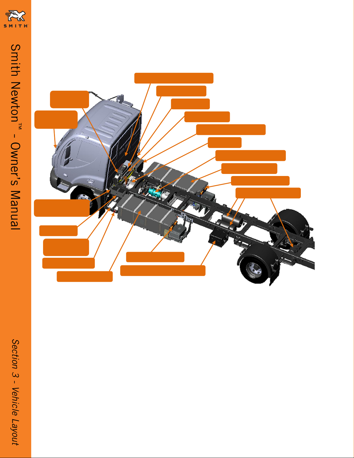
3. Vehicle Layout
Page | 10 © 2012 Smith Electric Vehicles CD-0650-0018r0
Main Drive Components
External Fuse Box
24V Isolator Switch
Figure 3.1
Circuit Breaker Box (RCD)
Drive Motor
Traction Battery Pod
Traction Battery Pod
24V (2x12V) Auxiliary Batteries**
Brake Air Compressor
24V (2x12V)
System Batteries
Driver’s Side
Charge Receptacle *
24V Chargers
*Charge receptacle location and connection type varies by vehicle
** Location of 12V Auxiliary Batteries varies by vehicle
Cabin Heater
(Under Hood)
Onboard Charger (Under Cab)
Motor Controller
Drive System
Coolant Tank
Battery Pod MSDs
Battery Pod MSDs
Air Brake Storage Tanks
Cab Tilt Valve
© 2012 Smith Electric Vehicles CD-0650-0018r0 Page | 11
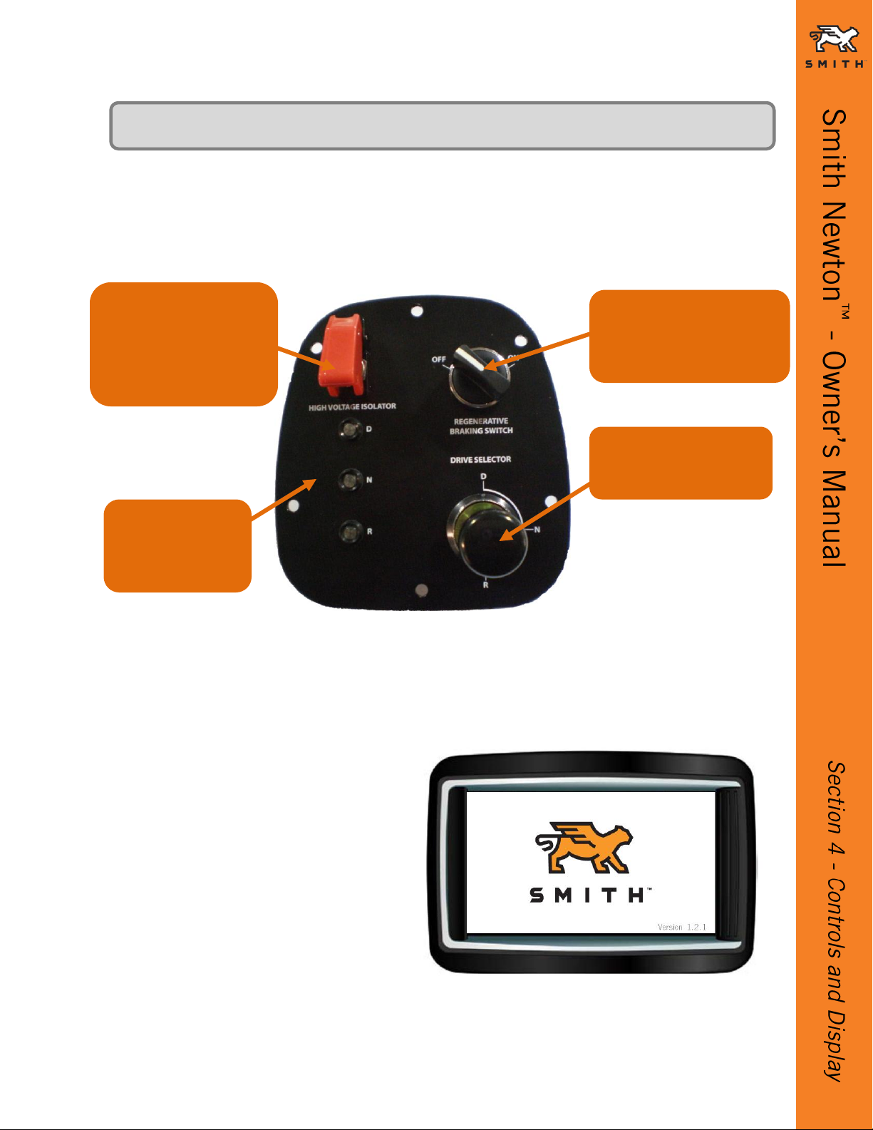
The vehicle Drive Controls are located next to the driver's seat in the middle console. (Figure
4.1)
EVIS Display –Start-Up
When the vehicle is started or placed
on charge, the Start-Up screen
(Figure 4.2) with the SMITH™ logo
will display. It may take up to 45
seconds for the Drive Mode screen
(Figure 4.3) or the Charge Mode
screen (Figure 5.5) to display.
The controls on the dashboard and steering column are outlined in the Avia Ashok Leyland
owner's manual. Different to a conventional vehicle, this vehicle is equipped with an electric
cabin heater. See Section 8.
4. Controls and Display
Figure 4.2
EVIS (Electrical Vehicle Information System)
The EVIS Display is mounted above the front windshield on the driver’s side.
High Voltage Isolator
Disconnects the high
voltage supply to the
drive system when
switched.
3 LEDs
D - Drive
N - Neutral
R - Reverse
Regenerative Braking
Switch
Activate or deactivate
regenerative braking.
Drive Selector
Drive, Neutral and
Reverse
Figure 4.1

Page | 12 © 2012 Smith Electric Vehicles CD-0650-0018r0
1
5
4
3
2
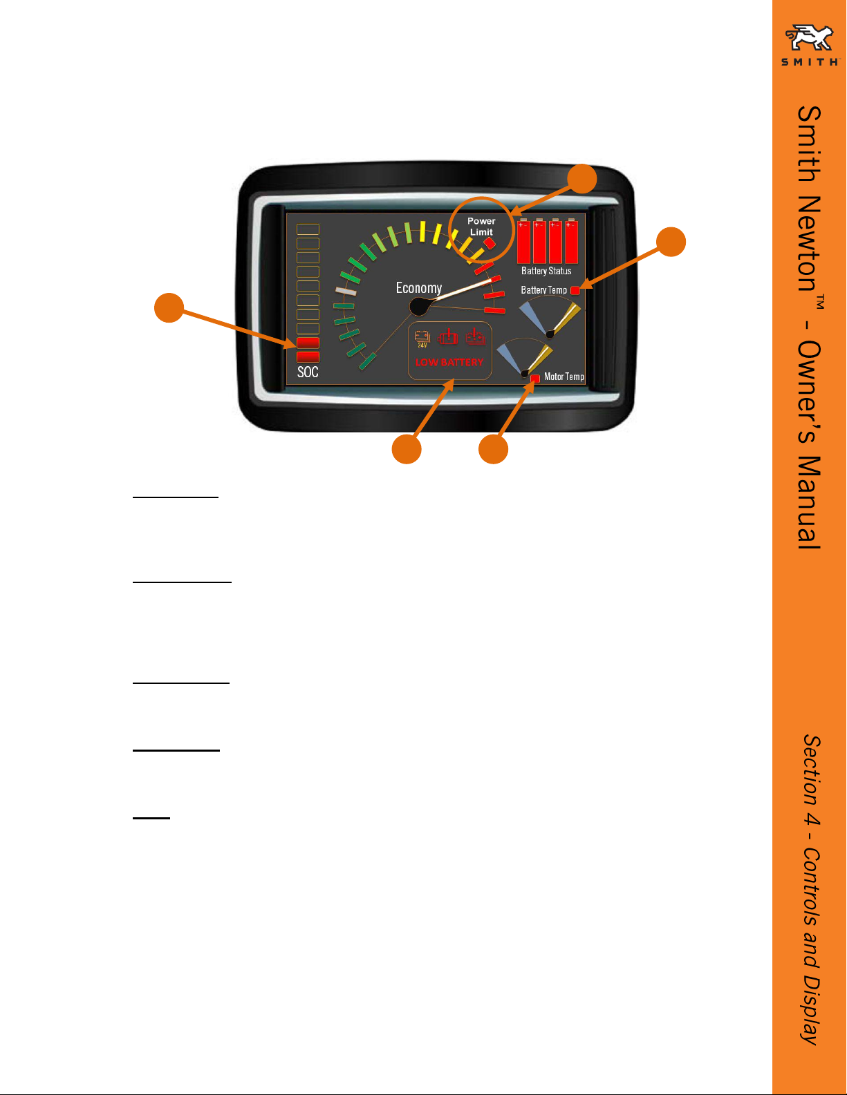
Figure 4.3
1. Economy
This displays instantaneous power
•The Gray Line is zero (no current in or out)
•Above the Gray Line = throttle applied / accelerating (current out of battery)
•Below the Gray Line = re-gen is occurring, either coast or braking (current being given back
to battery)
EVIS Display –Drive Mode (Figure 4.3)
2. Battery Status
BATTERY STATUS LIGHTS, one for each string, independently colorized as shown
•Green String Status = OK
•Amber String Status = WARNING
•Red String Status = FAULT (See Faults/Warnings)
•String Status = OFFLINE
3. Battery Temp
Battery Temperature Gauge has 3 needle positions; Center (Vertical), Right (Amber) and Left
(Blue).
•Vertical Center Position = within normal operational range
•Amber Section = battery is above first high thermal limit and depowered (limited)
•Blue Section = battery is below first low thermal limit and depowered (limited)
5. SOC (State of Charge)
•Each Green light in the column represents approximately 10% of the total SOC
•Fully charged will display all lights solid Green
•Starting with the top light, as energy is taken, each light will go out
•As the SOC drops below 50% the lights will turn Amber
•As the SOC drops below 20% the lights will turn Red (See Faults/Warnings)
4. Motor Temp
Motor Temperature Gauge has 3 needle positions; Center (Vertical), Right (Amber) and Left
(Blue).
•Vertical Center Position = within normal operational range
•Amber Section = motor or controller is above first high thermal limit and depowering
(limited)
•Blue Section = Motor or controller is below first low thermal limit and depowered (limited)
© 2012 Smith Electric Vehicles CD-0650-0018r0 Page | 13
1. Power Limit
•Red light and the Power Limit text illuminate when max available discharge current is less
than 250A or the SOC is less than 20%
•Invisible if inactive
2. Fault Window
•24V WARNING appears if there are low voltage system faults
•Power Train Fault Light appears if there are Controller or Traction Motor Faults
•Battery Fault Light appears for all Traction Battery Faults
•LOW BATTERY appears in the when SOC drops below 10%
3. Battery Temp
•Red Warning Light = Battery has reached maximum thermal limit and shut down. Light
visible only when illuminated (hidden tell-tale)
4. Motor Temp
•Red Warning Light = Motor or controller has reached maximum thermal limit and shut
down. Light visible only when illuminated (hidden tell-tale)
5. SOC (State of Charge)
•As the SOC drops below 20% the lights will turn Red
EVIS Display –Drive Mode –Faults/Warnings (Figure 4.4)
Figure 4.4
1
5
4
3
2

Page | 14 © 2012 Smith Electric Vehicles CD-0650-0018r0
This Page Intentionally Left Blank

© 2012 Smith Electric Vehicles CD-0650-0018r0 Page | 15
Locate and park the vehicle in a position that the charging receptacle is within 20 feet of the
AC charge point (EVSE), free of standing water and obstructions.
Place the vehicle in NEUTRAL, set the parking brake, and turn the ignition key to the LOCK
position.
The High Voltage Isolator Switch in the truck cab must be in the RUN position with the red
protective cover closed. (Figure 4.1)
The 24V Isolator Switch, located immediately behind the driver side of the cab, must be in
the RUN (HORIZONTAL) position. (Figure 5.1)
The High Voltage MSDs must be installed on each battery pod. (Figure 5.2)
Verify there is no damage to charging cable, cable ends, or charging connections. If any
damage is found, do not continue until replaced or repaired.
Remove the protective cover or cap from the vehicle connection.
Make cable connection to the vehicle end of the cable first. (Figures 5.3 & 5.4)
If applicable, lift the protective cover on the vehicle end of the cable and hold it open,
connecting the cable by aligning the index slot and push straight into the plug.
If applicable, re-engage the twist locking device.
Specification of Charge Facility
A. AC Power service shall be in accordance with the latest edition
of the National Electric Code.
B. Service requirement is dependent on vehicle configuration.
C. Refer to the truck’s configuration specification for battery pod
and phase arrangement.
Single Phase J1772, 75A
See Figure 5.3
3-Phase Pin & Sleeve, 63A
See Figure 5.4
Due to the emerging EV market, UL listed components may not be available. However,
components are available to meet the intent of the code. See SMITH Document CD-0650-0016,
AC Charging Connectivity. SMITH recommends user to consult with local inspector for
compliance or deviation as necessary.
5. Charging HV and 24V Systems
Figure 5.1
Figure 5.2
Run (HORIZONTAL)
Positions
Master Service
Disconnects (MSDs)

Page | 16 © 2012 Smith Electric Vehicles CD-0650-0018r0
Refer to charge point (EVSE) station manufacturer’s procedure to verify the AC power
charging source is OFF.
If so equipped, remove protective cover from the AC power socket.
Plug the cable into the AC power charging source.
Refer to charge point (EVSE) station manufacturer’s procedure to switch the AC power
charging source ON.
The EVIS Display –Start-Up
When the vehicle is placed on charge, the Start-Up screen (Figure 4.2) with the SMITH™ logo
will display. It may take up to 45 seconds for the Charge Mode screen (Figure 5.5) to display.
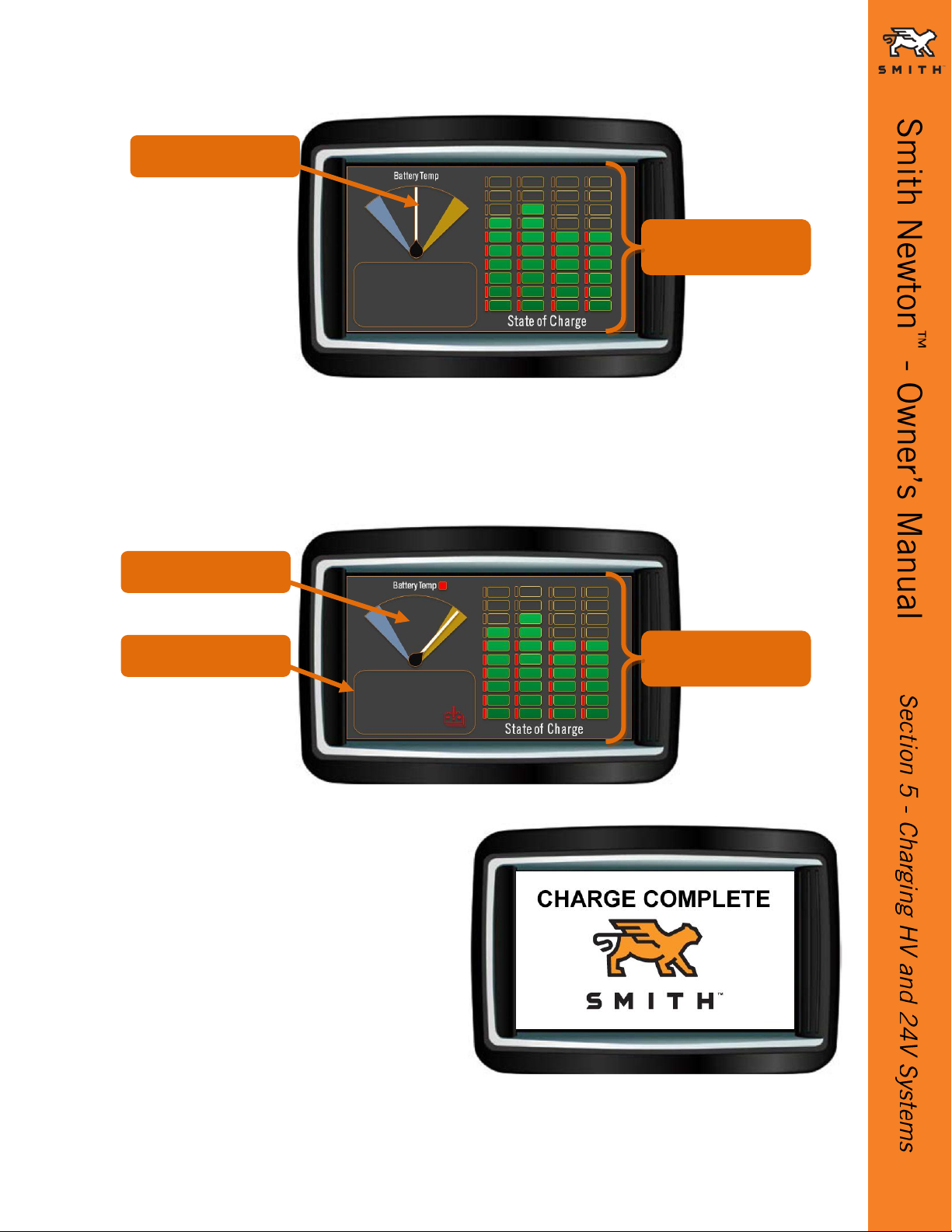
The EVIS Display in Charge Mode –No Faults/Warnings (Figure 5.5)
oBattery Temp
Vertical Position: Within normal operational range. Needle is not truly analog
and does not swing around.
Amber Section: Battery Temp is above first high thermal limit and
depowered (limited).
Blue Section: Battery Temp is below first high thermal limit and depowered
(limited).
oState of Charge, Green Column Lights
Each column of Green lights displays the SOC for each battery string.
Column one is for String 1, etc.
While charging, each column lights up solid Green progressively from the
bottom. Each light represents approximately 10% of the SOC.
When charge is complete, the EVIS Display will show CHARGE COMPLETE
with the SMITH™ logo. (Figure 5.7)
oCharge Current
Each Red column displays the Charge Current being taken by each string.
Column one is for String 1, etc.
Mid point on this scale is full charge when all strings are being charged at the
same rate. The full scale is restricted to when one string is being charged on
its own (when in catch-up mode).
When charge is almost complete, the current will be limited to the bottom
light.
Figure 5.3
Figure 5.4
Single Phase
3 - Phase
© 2012 Smith Electric Vehicles CD-0650-0018r0 Page | 17
The EVIS Display in Charge Mode –Faults/Warnings (Figure 5.6)
oBattery Temp
Amber Section: Battery Temp is above first high thermal limit and
depowered (limited).
Fault Window: Battery Fault light for all battery reported faults.
The traction batteries are fully
charged when the EVIS Display
shows CHARGE COMPLETE. (Figure
5.7)
SOC
State of Charge
Battery Temp
Figure 5.5
Figure 5.6
Battery Temp
Fault Window
SOC
State of Charge
Figure 5.7

Page | 18 © 2012 Smith Electric Vehicles CD-0650-0018r0
Charging progress of the 24V (2x12V) System batteries is displayed by the 50%, 75%, and
100% Green LED lights on the 24V charger. (Figure 5.8)
If there are any indications that the traction batteries or the 24V System batteries are not
receiving charge, or if there are any lights not illuminated on the Circuit Breaker Box (RCD)
(Figure 3.1), remove the circuit breaker box cover and check to make sure all of the circuit
breakers are in the ON (UP) position. (Figure 5.9)
NOTE:
The HV charger is liquid cooled, so after a short time, the coolant pump and fans under the cab
will begin to run.
The 24V batteries are fully charged when the 50%, 75%, and 100% Green LED lights on the
chargers are all fully illuminated. (Figure 5.8)
After charging is complete:
Refer to charge point (EVSE) manufacturer’s procedure to switch the AC power charging
source OFF.
Remove the AC power cable plug from the AC power service socket.
Disengage locking device and remove the AC power cable from the charging receptacle.
Inspect the charging cable, cable ends, and charging connections for damage and replace
and/or repair as necessary.
Coil AC power cable and store in an appropriate and dry location safe from damage.
Figure 5.9
Figure 5.8
WARNING
Only authorized personnel are allowed to work on the High Voltage
electrical power and/or control systems.

© 2012 Smith Electric Vehicles CD-0650-0018r0 Page | 19
Charging DOs and DON’Ts
DO...
DON’T...
Charge until the CHARGE COMPLETE screen displays
on the EVIS Display.
Plug in and unplug with the vehicle switched ON.
Opportunistic charging; charge if near a charge point
(EVSE) for a short period of time
Plug in and unplug with wall socket switched ON.
Remove from charge and isolate the 24V Battery
System If the vehicle will not be used for more than 3
days.
Leave the vehicle on charge if not used for 3 days or
longer.
Leave the vehicle connected to the charge point
(EVSE), when in daily operation, until it is ready to be
driven. This will ensure maximum battery power.
Use damaged charging cables or connectors.
Run the batteries down below 20% SOC (State Of
Charge) and then charged until the EVIS Display shows
CHARGE COMPLETE every month.
EVERY MONTH the batteries MUST be run down below 20% SOC (State of
Charge) and then fully recharged until EVIS Display shows CHARGE
COMPLETE. (Figure 5.7)

Page | 20 © 2012 Smith Electric Vehicles CD-0650-0018r0
This Page Intentionally Left Blank
Table of contents


