Koganei YMDA Series Guide

Catalog No.BK-C0030
HIGH MULTI CYLINDERS
KOGANEI Brand
All products are RoHS-Compliant
Compact & direct mounting
Directly mountable without mounting bracket!
A
A
A
A
A
A
A
A
A
A
A
A
A
l
l
l
l
l
l
l
l
l
l
l
l
l
l
l
l
l
l
p
p
p
p
p
p
p
p
p
p
p
p
p
p
p
p
p
p
p
p
p
p
p
p
p
r
r
r
r
r
r
r
r
r
r
r
r
r
r
r
r
r
o
o
o
o
o
o
o
o
o
o
o
ooo
o
o
o
o
o
d
d
d
d
d
d
d
d
d
d
d
d
d
d
d
u
u
u
u
u
u
u
u
u
u
c
c
c
c
c
c
c
c
c
c
c
t
t
t
t
t
t
t
t
t
t
s
s
s
s
s
s
s
s
s
s
s
s
s
s
s
s
s
s
s
s
s
s
s
s
a
a
a
a
a
a
a
a
a
a
a
a
a
a
a
a
a
a
a
a
a
r
r
r
r
r
r
r
r
r
r
r
eeeeee
e
R
R
R
R
R
R
R
R
R
R
R
R
R
R
R
R
R
R
R
R
R
R
R
R
R
R
o
o
o
o
o
o
o
o
o
o
o
o
o
o
o
o
o
H
H
H
H
H
H
H
H
H
H
H
H
H
H
H
H
H
H
H
H
H
S
S
S
S
S
S
S
S
S
S
S
S
S
C
C
C
C
C
C
C
C
C
C
C
C
o
o
o
o
o
o
o
o
m
m
m
m
m
m
m
m
m
m
m
m
m
m
m
m
m
m
m
m
m
m
m
m
m
m
p
p
p
p
p
p
p
p
p
p
p
p
p
p
p
p
p
p
p
p
p
p
p
p
p
p
p
p
p
p
p
p
p
p
p
p
p
p
ll
l
l
l
l
l
l
l
l
l
l
l
i
i
i
i
i
i
i
i
i
i
i
aa
a
a
a
a
a
a
a
a
a
a
a
a
a
n
n
n
n
n
n
n
n
n
n
n
n
n
n
n
n
n
n
n
n
n
t
t
t
t
t
t
t
t
t
t
t
t
t
KOGANEI Brand
All products are RoHS-Compliant

1
1
Directly mountable without mounting bracket,
realizing clean lines by embedded sensor switch.
Rectangular body and 6-face-mounting enable a compact and direct mounting.
Linear guide is installed to pursue space saving as well as non-rotating accuracy.
The embedded type sensor switch is employed to prevent anything protruding from the main body.
Sensor switches are placed in the sensor mounting groves located on the 2 faces of main body.
Compact &direct mounting
Standardizing cylinders with guides
The embedded sensor switch is employed
Body through hole for vertical mounting
Body through hole & counterbore
for flat surface mounting
Body mounting tap hole
of head-side flange type
Good for use in tight places
embedded type sensor switch
Body mounting tap hole
of rod-side flange type
Flat surface mounting with lower height
Space-saving flange type mounting
Vertical mounting with narrower width
HIGH MULTI CYLINDERS

2
2
I N D E X
Standard cylinders (double acting
type) K
Non-rotating cylinders RCylinders with guide V
Sensor switches A
Standard cylinders (single acting
push type) K
Standard cylinders (single acting
pull type) K
Features A
Safety Precautions C
Handling Instructions and Precautions G
Standard cylinders
(Double acting type, Single acting push type, and
Single acting pull type) K
Order code L
Inner construction and parts names M
Dimensions O
Non-rotating cylinders R
Order code S
Inner construction and parts names T
Dimensions U
Cylinders with guides V
Order code W
Inner construction and parts names X
Dimensions Y
Sensor switches A
Order code & Internal circuit diagram B
Contact protection countermeasure &
wiring instructions D
Usable minimum cylinder stroke E
Stroke end detection
Sensor switch mounting position F
VARIATION

3
Before selecting and using the products, please read all the "Safety Precautions" carefully to ensure proper product use.
The Safety Precautions described below are to help you use the product safely and correctly, and to prevent injury or damage to you, other people, and assets.
Be sure to observe these safety precautions together with the following safety regulations of ISO4414 (General rules and safety
requirements for systems and their components), and JIS B 8370 (General rules relating to systems).
DANGER
This product was designed and manufactured for use in general industrial machinery.
When selecting and handling equipment, the system designer or another person with sufficient knowledge and experience should always read
the "Safety Precautions", "catalog", "instruction manual", and other literature before commencing operation. Improper handling is dangerous.
After reading the instruction manual, catalog, and other documentation, always place them in a location that allows easy availability
for reference to users of this product.
Whenever transferring or lending the product to another person, always attach the catalog, instruction manual, and other information
to the product where they are easily visible in order to ensure that the new user can use the product safely and properly.
The danger, warning and caution items listed under these "Safety Precautions" do not cover all possible contingencies. Read the
catalog and instruction manual carefully, and always keep safety first.
DANGER
Indicates situations that can be clearly predicted as dangerous.
Death or serious injury may result if the situation is not avoided.
It could also result in damage or destruction of assets.
WARNING
Indicates situations that, while not immediately dangerous, could become dangerous.
Death or serious injury may result if the situation is not avoided.
It could also result in damage or destruction of assets.
CAUTION
Indicates situations that, while not immediately dangerous, could become dangerous.
Failure to avoid the situation creates the risk of minor or semi-serious injury.
It could also result in damage or destruction of assets.
ATTENTION While there is little chance of injury, this content refers to points that should be observed for appropriate
use of the product.
The directions are ranked according to degree of potential danger or damage: "DANGER", "WARNING", "CAUTION" and "ATTENTION."
Safety Precautions (High multi cylinder)
Do not use the product for the purposes listed below:
1.
Medical equipment related to maintenance or management
of human lives or bodies.
2.
Machines or equipment designed for the purpose of moving
or transporting people.
3.
Critical safety components in mechanical devices.
This product has not been planned or designed for purposes
that require high levels of safety. Using the product in any of the
ways described above creates the risk of loss of human life.
Do not use the product in locations with or near dangerous
substances such as flammable or ignitable substances. This product
is not explosion-proof. Doing so creates the risk of ignition and fire.
When mounting the product and workpiece, always make sure they
are firmly supported and secured in place. Falling, dropping, or
abnormal operation of the product creates the risk of personal injury.
Persons using a pacemaker or other similar medical devices should
maintain a distance of at least 1 meter [3.28 ft] away from the product.
Getting too close to the product creates the risk of malfunction
of a pacemaker due to the strong magnet built into the product.
Never attempt to modify the product in any way. Doing so creates the
risk of injury, electric shock, fire, etc. due to abnormal operations.
Never attempt inappropriate disassembly, assembly, or repair of the
product relating to basic construction, or to its performance or functions.
Doing so creates the risk of injury, electric shock, fire, etc.
Do not allow water to splash on the product. Water spraying on the
product, washing the product, or using the product under water creates
the risk of malfunction, leading to injury, electric shock, fire, etc.
While the product is in operation, avoid touching it with your hands or
otherwise approaching too close. Also, do not attempt to make any
adjustments to internal or attached mechanism, or to perform any type of
adjustment (adjusting the mounting position of sensor switches, disconnecting
piping tubes or sealed plugs, etc.) while the product is in operation.
This may cause a sudden cylinder movement or any other
items that creates the risk of personal injury.
When operating the product, always install speed controllers, and gradually
loosen the needle valve from a choked state to adjust the increase in speed.
Failure to make this adjustment, sudden movements can take
place by the air supply, which may cause the loss of human life.
Do not apply the load exceeding the buckling/bending strength to
the piston rod. This can cause to shorten the product operating life
and to create abnormal wear or breakage of rods and tubes.
Make sure to align the piston rod axis and the load moving
direction. Failure to do so, straining force will be applied to the
piston rod or the tube, causing abnormal wear or breakage.
WARNING
Do not use the product in excess of its specification ranges. Doing
so creates the risk of product breakdown, loss of function, or
damage. It could also drastically reduce the product's operating life.
Before supplying air or electricity to the device and before
starting operation, always conduct a safety check of the area
where the machine is operating. Unintentional supply of air or
electricity creates the risk of electric shock or injury due to
contact with moving parts.
Do not touch terminals or switches while power is turned on. Doing
so creates the risk of electric shock and abnormal operation.
Do not allow the product to be thrown into fire.
Doing so creates the risk of explosion, resulting in the release
of toxic gasses.
Do not sit on the product, place your foot on it, or place other
objects on it.
Doing so creates the risk of injury due to tripping or the
product tipping over or dropping, resulting in product damage
and abnormal, erratic or runaway operation.
Before conducting maintenance, inspection, repair,
replacement, or any other similar procedure, always
completely cut off all air supply and confirm that residual
pressure inside the product or in piping connected to the
product is zero.
In particular, be aware that residual air will still be in the
compressor or storage tank. The cylinder may move abruptly if
residual air pressure remains inside the piping, causing injury.
Do not use the cylinder as a device aiming to absorb the
shock or vibration of machinery. Doing so may create the risk
of injury or the breakdown of the machinery.
Do not allow lead wires of sensor switches and other cords to
become damaged.
Allowing a cord to become damaged, bent excessively, pulled,
rolled up, placed under heavy object, or squeezed between two
objects creates the risk of current leaks or defective continuity
that can lead to fire, electric shock, or abnormal operation.
While cylinder is in motion, do not apply external magnetic
field to sensor switches. Doing so creates the risk of
unintentional movement of the product, resulting in breakdown
of equipment or personal injury.
Use the product within the range of recommended load and
specified speed. Using outside the range creates the risk of
damaging the cylinder, resulting the breakdown of the
equipment or personal injury.
Use safety circuits or design a system that prevents damage
to machinery and personal injury when the machine is shut
down due to an emergency stop or electrical power failure.
Always read these precautions carefully before use.

4
Always read these precautions carefully before use.
CAUTION
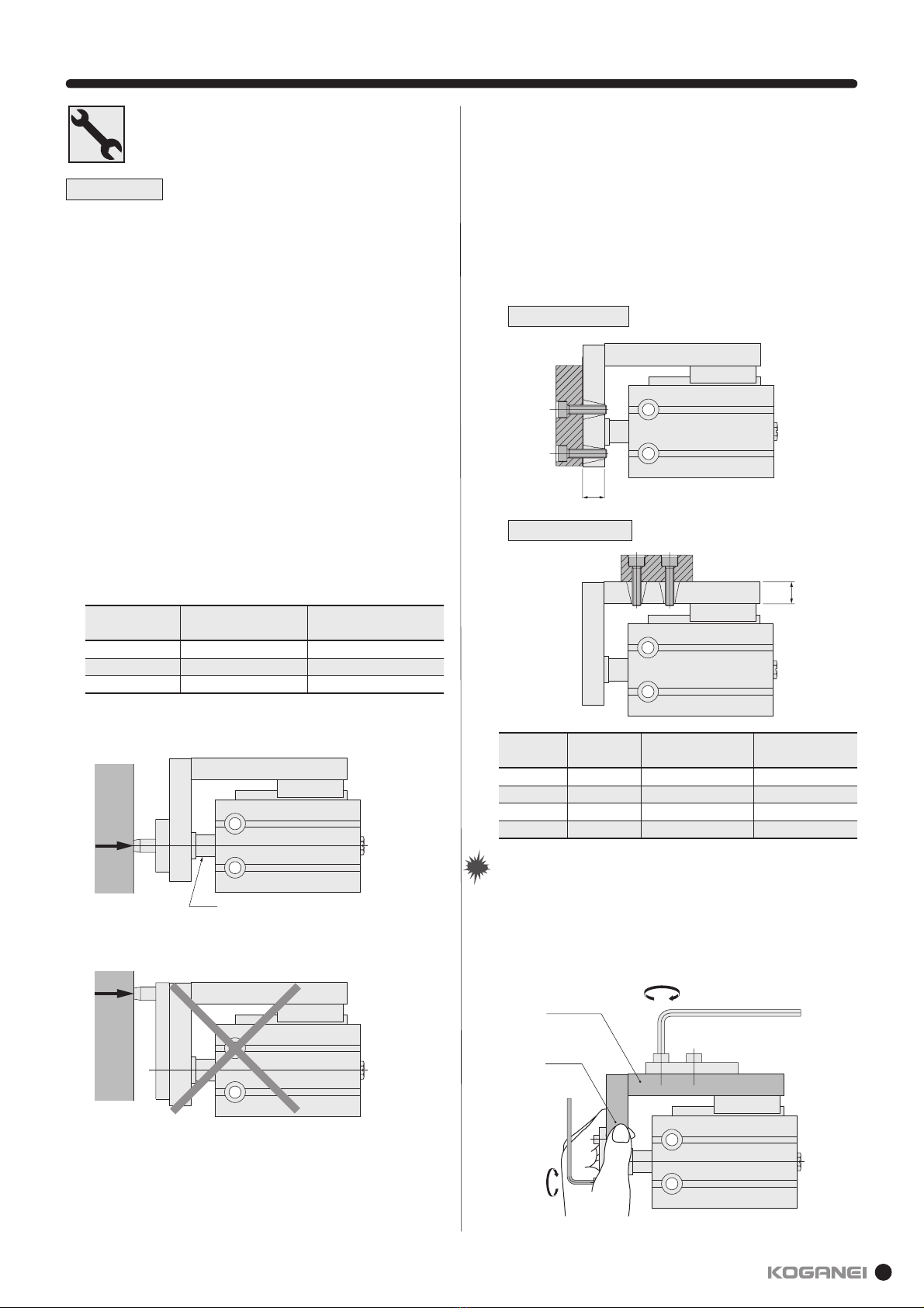
When mounting the product, leave room for adequate working
space around it. Failure to do so will make it more difficult to
conduct daily inspections or maintenance, which could eventu-
ally lead to system shutdown or damage to the product.
Do not bring any magnetic media or memory within one meter
[3.28 ft] of the product. Doing so creates the risk of damage to
data on the magnetic media due to magnetism.
The sensor switch should not be used in a location where high
current or magnetic field is generated. This may cause the
machine to malfunction.
Also avoid using magnetic material for any parts used for
mounting. Doing so creates the risk of magnetism leakage that
causes malfunctions.
Do not bring the product close to magnetized body. Bringing
the product close to magnetized body or the location where
high magnetic field is generated can magnetize the main body
or table, resulting the malfunction of sensor switches or defec-
tive operation due to attachment of the iron powder.
Make absolute sure that sensor switches of other companies
are not used for this product.
Failure to do so can lead to malfunctions or runaway
operations.
Do not scratch, dent, or deform the actuator by climbing on the
product, using it as a scaffold, or placing objects on top of it.
Doing so creates the risk of damage to or breakage of the
product, resulting in operational shutdown or degraded
performance.
Always post an "operations in progress" sign for installations,
adjustments, or other operations, to avoid unintentional
supplying of air or electrical power, etc. Unintended power or
air supply can cause electric shock or sudden cylinder
movement, creating the risk of personal injury.
Do not apply excessive load to the cords, such as the lead
wires of sensor switches mounted on the cylinder, in such
manner as pulling, carrying by hands or placing heavy object
on the cords. Doing so may cause the leak current or defective
continuity, leading to fire, electric shock or malfunctions.
When the pressure is increased by external force, make sure
to attach the relief equipment or any other means not to
exceed the specified operating pressure of the cylinder.
Pressure exceeding the specified operating pressure may lead
to malfunction and breakdown.
When the machine has been idle for over 48 hours or is in first
operation after storage, it is possible that the contacting parts
may have become stuck, leading to operation delays or
sudden movements. In initial operation, be sure to perform trial
operation to check whether the machine works properly.
Never use the product in direct sunshine-suffered location like
beach, near mercury lamp, or near a product likely to produce
ozone. Deterioration of rubber parts caused by ozone may
reduce the performance and function or stop the function.
Because KOGANEI products may be used under a wide
variety of conditions, decisions concerning conformance with
a particular system should be made upon the careful
evaluation by the person in charge of system design.
Assurances concerning expected system performance and
safety are the responsibility of the designer who decides
system conformity. Be sure to use the latest catalogs and
technical materials to study and evaluate specification details,
to consider the possibility of machine breakdown, and to
configure a system that ensures fail-safe safety and reliability.
Do not use in locations that are subject to direct sunlight
(ultraviolet rays), in locations with dust, salt, or iron particles,
or in locations with media and/or ambient atmosphere that
include organic solvents, phosphate ester type hydraulic oil,
sulfur dioxide, chlorine gas, acids, etc. Such uses could lead to
early shutdown of some functions, a sudden degradation of
performance, and a reduced operating life. For details on
materials used in the product, refer to the description of major
parts.
Always observe the following items.
KOGANEI shall not be held responsible for any problems that
occur as a result of these items not being properly observed.
1.
When using this product in pneumatic systems, always use genu-
ine KOGANEI parts or compatible products (recommended parts).
When conducting maintenance and repairs, always use genuine
KOGANEI parts or compatible products (recommended parts).
Always observe the prescribed methods and procedures.
2.
Never attempt inappropriate disassembly or assembly of the prod-
uct relating to basic construction, or its performance or functions.
KOGANEI shall not be held responsible for any problems that occur
as a result of these safety precautions not being properly observed.
Others
ATTENTION
Whenever considering use of this product in situations or
environments not specifically noted in the "catalog" or "instruction
manual", or in applications where safety is an important requirement
such as in aircraft facilities, combustion equipment, leisure equipment,
safety equipment, and other places where human life or assets may
be greatly affected, take adequate safety precautions such as allowing
plenty of margin for ratings and performance, or fail-safe measures.
Be sure to contact KOGANEI before use in such applications.
Always check the "catalog" and other reference materials for
product wiring and piping.
Moving parts of machine and devices should be isolated with a
protection cover so as not to be directly contacted by human body.
Do not configure the control that may cause a workpiece to
drop when in power outage.
Be sure to configure the work/table-drop prevention control for
the case of power outage or emergency stop of the machine.
When handling the product, wear protective gloves, safety
glasses, safety shoes, etc., as required.
When the product can no longer be used or is no longer
necessary, dispose of it appropriately as industrial waste.
Pneumatic equipment can exhibit degraded performance and
function over its operating life. Always conduct daily inspections of
the pneumatic equipment, and confirm that all requisite system
functions are satisfied, to prevent accidents from happening.
For inquiries about the product, consult your nearest KOGANEI
sales office or KOGANEI overseas group. The addresses and tele-
phone numbers are shown on the back cover of this catalog.
Safety Precautions (High multi cylinder)
Warranty and General Disclaimer
1. Warranty Period
The warranty period for KOGANEI products is 180 days from
the date of delivery.
2. Scope of Warranty and General Disclaimer
(1)
The KOGANEI product warranty covers individual products. When a
product purchased from KOGANEI or from an authorized
KOGANEI distributor malfunctions during the warranty period in a
way that is attributable to KOGANEI responsibility, KOGANEI will
repair or replace the product free of charge. Even if a product is still
within the warranty period, its durability is determined by its
operation cycles and other factors. Contact your nearest KOGANEI
sales office or the KOGANEI overseas group for details.
(2)
KOGANEI shall not be held responsible for any losses or for
any damage to other machinery caused by breakdown, loss
of function, or loss of performance of KOGANEI products.
(3)
KOGANEI shall not be held responsible for any losses
due to use or storage of the product in a way that is
outside of the product specifications prescribed in
KOGANEI catalogs and the instruction manual, and/or
due to actions that violate the mounting, installation,
adjustment, maintenance and other safety precautions.
(4)
KOGANEI shall not be held responsible for any losses
caused by breakdown of the product due to factors
outside the responsibility of KOGANEI, including but not
limited to fire, natural disaster, the actions of third
parties, and intentional actions or errors by you.

5
Installation and adjustment
Always read these precautions carefully before use.
WARNING WARNING
1.
Check for internal voltage drop of sensor switches.
When reed sensor switches with indicator lamps or 2-lead
wire solid state sensor switches are connected in series
causes increasing internal voltage drop, and the load may fail
to activate. Connecting n-pieces will drop the internal voltage
by n times as large.
Ensure the circuit satisfy the following inequality.
Power supply voltage — Internal voltage drop×n > Minimum
operating voltage of the load
In relays with rated voltage of less than 24VDC, check to see
the above inequality is satisfied even when n=1.
When the above inequality is not satisfied, select a reed sen-
sor switch without indicator lamp.
2.Do not use Koganei sensor switches with other com-
pany's cylinders.
The sensor switches are designed for use with our Koganei
cylinders only. Using with other company's cylinders may not
function properly.
1.Check the specifications.
Using outside of specification range in voltage, current, temper-
ature, shock, etc. creates the risk of breakdown or malfunctions
of the product. Read the specification carefully before using.
2. Avoid mounting cylinders in close proximity to each othe
r
When more than two cylinders with sensor switches are used
close to each other, see page E. This can cause the sensor
switch to malfunction due to the magnetic interference with
each other.
3.
Where the position detection is made at mid-stroke,
be cautious against the sensor switch ON time.
Be aware that, when the sensor switch is mounted at interme-
diate point of cylinder stroke to detect passing of the piston,
too fast speed of the piston can shorten the sensor switch
operation time, causing the load, such as programmable con-
trollers, to fail to operate.
The highest detectable cylinder speed is
4.
Keep wiring as short as possible.
The wiring for solid state sensor switches must be 30 m
[98.4ft] or shorter, as stipulated by EN standard. For reed sen-
sor switches, the longer wiring (10 m [32.8 ft] or longer) will
lead to the larger capacitive surge current, which reduces the
operating life of sensor switches. When a longer wiring cannot
be avoided, provide the protective circuit described in the cat-
alog.
If the load is inductive or capacitive, provide the appropriate
protective circuit as described in the catalog.
5.Avoid repeated bending or excessive pulling of lead
wires.
Applying repeated bending or pulling force on the lead wires
could cause breaking the wire.
6.Check for leakage current.
2-lead wire solid state sensor switches produce the current
(leakage current) even at off condition to activate the internal
circuit. Ensure that they satisfy the following inequality:
Input off current of programmable controller > Leakage current
If above inequality is not satisfied, select 3-lead wire solid
state sensor switch. And, if n-pieces sensors are connected in
parallel, the leakage current increases by n times.
1. Do not apply an external magnetic field to the sensor
switch while the cylinder is in operation.
This may cause unintended operation, thereby damaging the
device and causing personal injury.
V [mm/s] =
Sensor switch operating range [mm]
Time required for load operation [ms]
×1000
Design and Selection
CAUTION
1.Ensure a safe installation environment for the cylin-
ders with sensors.
The sensor switch should not be used in a location where
large current or high magnetic field is present. It could result
in erratic operation.
Do not use magnetic material for the mounting portion. This
may cause erratic operation.
2.Install the sensor switches in the center of their
operating range.
Adjust the mounting position of the sensor switch so that the
piston can stop in the center of the operating range (the sen-
sor turned-on range). Setting the switch ON the end of the
operating range (at the boundary of ON/OFF) may cause the
operation to be unstable. Also be aware that the operating
range will vary according to the temperature change.
3.Follow the tightening torque for the sensor switches
when mounting.
Tightening the screw exceeding the allowable tightening
torque may damage the mounting thread, mounting bracket,
sensor switch etc. In addition insufficient tightening torque
could cause the sensor switch position to be changed, there-
by resulting in unstable operation. For details about tightening
torque, refer to Page E.
4.Do not carry the cylinder by its mounted sensor
switch's lead wire.
After mounting a sensor switch on the cylinder, do not carry
the cylinder by grabbing the lead wire. This may not only dam-
age the lead wire but also apply stress to the inside of the
sensor switch that may damage internal elements, so never
perform such behavior.
5.Do not drop the sensor switches or bump them
against other objects.
When handling the product, take care to avoid dropping it,
allowing it to bump against other objects, or otherwise sub-
jecting it to excessive impact (294.2 m/s [30G] or more).
In the case of reed sensor switches, such behavior may
cause the contact to malfunction, thereby giving a signal
instantaneously or turning off the signal. And, this may
change the contact interval, thereby deteriorating the sensor
switch's sensitivity. As such, this may cause the device to mal-
function. Even if the sensor switch case is not damaged, the
inside of the sensor switch may be damaged, causing erratic
operation.
CAUTION
Safety Precautions (Sensor switch)

6
1.Prevent nearby moving objects from coming into
contact with sensor switches.
When the cylinders equipped with sensor switches are mov-
ing, or when moving objects are nearby, do not let them come
into contact each other. In particular, lead wires may become
worn or damaged causing unstable operation of the sensor
switch. In the worst case , this may result in current leakage or
electric shock.
2.Always turn off the power before performing wiring
work.
Wiring work while the power is on could result in electric
shock. Also, incorrect wiring could damage the sensor switch
in an instant. Turn on the power after completing the wiring
work.
1.Check the "catalog" and other reference materials
for correct wiring.
Improper wiring could result in abnormal operation.
2.Do not share wiring with power or high voltage lines.
Avoid wiring in parallel to or shared in the same conduit with
power line and high-voltage line. Such wiring could cause the
sensor switch and control circuit to suffer erratic operation by
electric noise.
3.Be cautious against not bending the lead wire
repeatedly or applying tension force to the wire.
Applying repeated bending stress or tension force to the lead
wire may cause the wire to be broken.
4.Check polarity in the wiring.
For the sensor switch with the polarities (+, −, output) indicat-
ed, make sure that wiring connections are correct. The wrong
polarities will result in damage to sensor switches.
Wiring
DANGER
WARNING
Safety Precautions (Sensor switch)
1. Avoid short circuiting loads.
Turning on the sensor switch while the load is short-circuited
causes overcurrent, which will damage the sensor switch in
an instant.
Example of short-circuit load: Sensor switch’s output lead wire
is directly connected to the power supply.
CAUTION
Always read these precautions carefully before use.

7
Handling Instructions and Precautions
In single acting type, when applying air from the piping port of
the cylinder and leaving the cylinder for long hours with the
spring compressed, the piston may not be returned even if the
air is exhausted. In such cases, use double acting type cylinders.
Cylinder with magnet (the sensor cylinder) has a built-in magnet
for sensor switch. Mounting the sensor switch enables the
detection of piston position.
1. Before piping for the cylinder, always flush the piping
completely by blowing compressed air through it. Entering
machining chips, sealing tape, or rust produced during piping
work may cause operating failures including air leakage.
2. When screwing a piping or fitting into the cylinder, be sure to
tighten them under appropriate tightening torque shown below.
Piping
The cylinder can be used without lubrication, but if lubrication is
required, use turbine oil Type 1 (ISO VG32) or equivalent. Do not
use spindle oil and machine oil.
Lubrication
1. When using the cylinder in a location subject to water droplet
and oil droplet or likely to be exposed to dust, protect the
cylinder with something to cover.
2. Do not use the cylinder in a corrosive atmosphere. The use of
the cylinder under such atmosphere may damage the cylinder
or cause its defective operation.
3. Do not use the cylinder under extremely dry condition.
4. The ambient temperature range most suitable for using the
cylinder is 5 to 60°C [41 to 140°F]. The temperature exceeding
60°C [140°F] may damage the cylinder or cause defective
operation, so be sure to avoid using the cylinder under such
conditions. And, the temperature 5°C [41°F] or below may
cause moisture in the air to be frozen, thereby damaging the
cylinder or causing defective operation. Take some anti-
freezing measure.
Atmosphere
When used
Others
Sensor switch
1. Use air as the media. For the use of any other media, consult
our nearest sales office.
2. For air used in the cylinder, be sure to use clean air which
does not contain degraded compressor oil, etc. Install an air
filter (filtration of 40µm or less) near the cylinder or valve to
remove sedimentation and dust. Also drain the air filter
periodically. Entering of impurities and dust into the cylinder
may cause its operating failure.
Air supply
General precautions
NoteNote 1. For mounting position and moving procedure of the
sensor switch, refer to E Page F.
2. When an inductive load will be connected to reed sensor
switches or if capacitive surge will occur, take some
contact protection countermeasures. For contact
protection countermeasures, refer to Page C.
1. Do not place your hands in the cylinder operating direction.
2.
In the initial operation, be cautious against cylinder operating direction.
3.
When the cylinder is retracting, be cautious against part of your body
not be caught in a gap between the cylinder body and the end plate.
4. At the time of maintenance, be sure to check that there is no
residual pressure within the cylinder before performing the work.
5. The cylinder speed should be 500 mm/s or less when using
the cylinder. However, even within the allowable range, if the
speed and load are large, install an external stopper to avoid
applying direct impact to the cylinder.
6. Use the cylinder at the value below the allowable kinetic
energy shown in the following table.
Kinetic energy of load is calculated using the following formula.
Ex = m
2
v
2
Ex: Kinetic energy (J)
m: Mass of load (kg)
v: Piston speed (m/s)
Cylinder bore
mm [in.]
6 [0.236]
10 [0.394]
16 [0.630]
20 [0.787]
Allowable kinetic energy
J [in · lbf]
0.007 [0.062]
0.018 [0.159]
0.031[0.274]
0.044 [0.389]
Connecting thread
M3
×
0.5
M5
×
0.8
Tightening torque N · m [in · lbf]
0.29 [2.57]
1.37 [12.13]
Model
YMDA
(Double acting type)
YMSA
(Single acting push type)
YMTA
(Single acting pull type)
YMDAL
(Non-rotating double acting type)
φ
D (mm [in.]
)
6 [0.236]
10 [0.394]
16 [0.630]
20 [0.787]
6 [0.236]
10 [0.394]
16 [0.630]
20 [0.787]
6 [0.236]
10 [0.394]
16 [0.630]
20 [0.787]
6 [0.236]
10 [0.394]
16 [0.630]
20 [0.787]
R
2
(mm [in.])
9.0 [0.354]
10.0 [0.394]
11.5 [0.453]
14.5 [0.571]
17.5 [0.689]
20.0 [0.787]
21.0 [0.827]
24.5 [0.965]
9.0 [0.354]
11.0 [0.433]
11.5 [0.453]
14.5 [0.571]
9.0 [0.354]
10.0 [0.394]
12.0 [0.472]
14.5 [0.571]
R(mm [in.])
25.0 [0.984]
28.0 [1.102]
29.5 [1.161]
33.5 [1.319]
21.5 [0.846]
23.0 [0.906]
25.0 [0.984]
28.5 [1.122]
25.0 [0.984]
28.0 [1.102]
29.5 [1.161]
33.5 [1.319]
25.0 [0.984]
33.0 [1.299]
34.5 [1.358]
43.5 [1.713]
R (N [lbf.])
0.99 [0.223]
2.75 [0.618]
7.04 [1.583]
10.99 [2.471]
0.74 [0.166]
2.27 [0.510]
5.97 [1.342]
10.05 [2.259]
0.50 [0.112]
1.58 [0.355]
4.95 [1.113]
7.29 [1.639]
0.99 [0.223]
2.75 [0.618]
7.04 [1.583]
10.99 [2.471]
Dimensions
Note: In the case of sensor cylinder, use the value R
2 shown in the table by
adding the value shown below as new R
2for calculating maximum
allowable lateral lead.
φ6 [0.236] to φ16 [0.630]: +5 [0.197], φ20 [0.787]: +10 [0.394]
W ≤·R
R2
R1+R2
R2R1=(R+St)
φD
R
Allowable lateral load
Use the cylinder under the condition below the following maximum
allowable lateral load.
Based on JIS Standard B8377 "Pneumatic cylinder"
Maximum allowable lateral load

8
Handling Instructions and Precautions
Mounting
1. Any mounting posture is available but the mounting surface
should be flat surface. Occurrence of twist or bending when in
installation could not only deteriorate the accuracy but also
cause air leakage or defective operations.
2. Take caution that scratched or dented mounting surface of the
cylinder may deteriorate the flatness.
3. When the impact is too large, be sure to install some support
bracket on the cylinder in addition to mounting screws.
4. Ensure to keep enough strength for the cylinder and
mounting screws.
5. When the screws may be loosened by the impact or vibration,
take measures against screw loosening.
6. The sliding portion of the piston rod should not be scratched
or dented. Scratched or dented sliding portion could damage
seals and cause air leakage.
7. Do not wipe out the grease applied on the piston rod and
linear guide. This may cause the product to defective
operation. If oil cannot be found, apply grease to them.
(Grease: Universal type Lithium based grease No. 2)
8. To tighten the cylinder, use the following tightening torque.
When using female threads of the main body for mounting,
tighten the screw under the tightening torque shown in ( ).
Mounting
Avoid the following usages.
9. When thrust of a cylinder with guide directly apply to the plate,
apply the force to the rod axis center.
Cylinder bore
mm [in.]
6 [0.236] · 10 [0.394]
16 [0.630]
20 [0.787]
M3
×
0.5
M4
×
0.7
M5
×
0.8
1.08 [9.56] (0.59 [5.22])
2.45 [21.68] (1.37 [12.13])
5.10 [45.14] (2.84 [25.14])
Screw size Tightening torque
N · m [in · lbf]
Rod
10. Mounting of workpiece
For the cylinder with guide, a workpiece can be mounted on
two surfaces.
To tighten screws for mounting a workpiece, tighten at a
torque within its limited range.
1. As the plate table is supported by the linear guide, do not
apply strong impact or excessive moment to it when
mounting a workpiece.
2. When securing a workpiece in a plate table with screws,
hold the table to tighten screws. Tightening with the body
held may apply excessive moment to the guide portion,
causing deteriorating the accuracy.
Cylinder bore
mm [in.]
06 [0.236]
10 [0.394]
16 [0.63]
20 [0.787]
M3×0.5
M3×0.5
M4×0.7
M5×0.8
0.59 [5.22]
0.59 [5.22]
1.37 [12.13]
2.84 [25.14]
5 [0.197]
6 [0.236]
8 [0.315]
10 [0.394]
Screw size
Maximum tightening torque
N · m [in · lbf]
H
mm [in.]
Front surface mounting
H
Upper surface mounting
H
Table
Plate
NoteNote

9
Rolling moment
Yawing moment
Pitching moment
6 [0.236]
10 [0.394]
16 [0.630]
20 [0.787]
A
30 [1.181]
35 [1.378]
39 [1.535]
49 [1.929]
B
6 [0.236]
7 [0.276]
9.5 [0.374]
12 [0.472]
Handling Instructions and Precautions
Cylinder with guide - Allowable bending moment
Allowable loads Fp, Fy, Fr calculation formula
Allowable bending moment
Moment from guide center location distance compensation
N · m [in · lbf]
6 [0.236]
10 [0.394]
16 [0.630]
20 [0.787]
Mp (Pitching)
0.39 [3.45]
0.39 [3.45]
0.51 [4.51]
1.02 [9.03]
Mr (Rolling)
0.58 [5.13]
0.58 [5.13]
1.02 [9.03]
2.08 [18.41]
My (Yawing)
0.47 [4.16]
0.47 [4.16]
0.51 [4.51]
1.02 [9.03]
Cylinder
bore mm [in.]
Cylinder
diameter mm [in.]
Allowable bending
moment
mm [in.]
Pitching (Mp) Yawing (My)
Rolling (Mr)
Guide center location B
A+Stroke
For each moment center position, use the guide center location shown
in the figure as the reference.
Applications exceeding the allowable bending moment may damage the guide portion and deteriorate the accuracy, thereby affecting the operating life.
Symbol
Center of the guide
Lp A+St
Fp
Mp
Fr
Mr
Lr B
Center of the guide
Ly A+St
Fy
My
Center of the guide
Fp = Mp ×1000 (N)
Lp : Distance between the plate and the load (mm)
A+St :
Distance between the plate and the center of the guide (mm)
St : Cylinder stroke (mm)
Lp +(A +St)
Fy = My ×1000 (N)
Ly : Distance between the plate and the load (mm)
A+St :
Distance between the plate and the center of the guide (mm)
St : Cylinder stroke (mm)
Ly +(A +St)
Fr = Mr ×1000 (N)
Lr : Distance between the plate and the load (mm)
B : Distance to the center of the guide (mm)
Lr +B

10
Mounting procedure for the rear piping base
Deflection of the plate end (Reference value)
For the rear piping base of high multi cylinder with guide, the rear piping base is provided as an accessory when shipping
from factory. Assemble the base on the unit in the manner shown below.
0.00
0.05
0.10
0.15
0.20
0 1020304050
Stroke (mm)
(mm)
5(N)
3(N)
1(N)
Deflection
0.00
0.05
0.10
0.15
0.20
0 1020304050
(mm)
(mm)
5(N)
3(N)
1(N)
Stroke
Deflection
0.00
0.05
0.10
0.15
0.20
0 1020304050
6(N)
4(N)
2(N)
(mm)
(mm)
Stroke
Deflection
0.00
0.05
0.10
0.15
0.20
0 1020304050
9(N)
7(N)
5(N)
(mm)
(mm)
Stroke
1 mm = 0.0394 in 1 N = 0.2248 lbf
Deflection
Cylinder bore φ6 [0.236 in] Cylinder bore φ16 [0.630 in]
Cylinder bore φ10 [0.394 in]Cylinder bore φ20 [0.787 in]
W(N)
Stroke
1. Remove a plug on the head cover.
(To attach the plug again, tighten at the tightening torque of 0.59 N·m
[5.22 in·lbf].)
2. Place supplied O-rings as shown in the figure, and install the base
with supplied hexagon socket head screws. At that time, use the
following tightening torque.
Cylinder bore
mm [in.]
6 [0.236] · 10 [0.394]
16 [0.630]
20 [0.787]
Hexagon socket head screw
M3
×
0.5
M4
×
0.7
M5
×
0.8
Tightening torque
N · m [in · lbf]
0.59 [5.22]
1.37 [12.13]
2.84 [25.14]
Hexagon socket head screw
Remove the plug
O-ring
Rear piping base

11
Double acting type, single acting push/pull type
Air
0.2〜0.7 [29〜102]
1.05 [152]
0〜60 [32〜140]
50〜500 [2〜20]Note
Rubber bumper
Not required (If used, use turbine oil class 1 [ISO VG32] or equivalent)
M5×0.8
Symbol
Specifications
Cylinder bore and stroke
6 [0.236]
0.15〜0.7 [22〜102]
0.2〜0.7 [29〜102]
0.3〜0.7 [44〜102]
16 [0.630]
0.15〜0.7 [22〜102]
0.08〜0.7 [12〜102]
20 [0.787]
0.15〜0.7 [22〜102]
Bore
6 [0.236]
10 [0.394]
16 [0.630]
20 [0.787]
6 [0.236]
10 [0.394]
16 [0.630]
20 [0.787]
Operation type
Double acting type
Single acting push type
Single acting pull type
Standard stroke
5 · 10 · 15 · 20 · 25 · 30 · 40 · 50 · 60
5 · 10 · 15 · 20 · 25 · 30 · 40 · 50 · 60 · 70 · 80 · 90 · 100
5 · 10 · 15
Maximum manufacturable stroke
60
100
15
Standard cylinders
Double acting type
Single acting push type
Single acting pull type
Item
Operation type
Media
Operating pressure range
MPa [psi.]
Proof pressure MPa [psi.]
Operating temperature range °C [°F]
Operating speed range
mm/s [in/sec]
Cushion
Lubrication
Port size
Double acting type
Single acting push type
Single acting pull type
Thrust
0.1 [15]
—
—
—
—
7.9 [1.78]
5.9 [1.33]
—
—
20.1 [4.52]
17.2 [3.87]
—
—
31.4 [7.06]
23.5 [5.28]
—
—
0.2 [29]
5.6 [1.26]
4.2 [0.94]
0.7 [0.16]
—
15.7 [3.53]
11.8 [2.65]
6.1 [1.37]
2.2 [0.49]
40.2 [9.04]
34.4 [7.73]
18.8 [4.23]
13.0 [2.92]
62.8 [14.12]
47 [10.57]
44 [9.89]
28.2 [6.34]
0.3 [44]
8.5 [1.91]
6.4 [1.44]
3.5 [0.79]
1.5 [0.34]
23.6 [5.31]
17.7 [3.98]
13.9 [3.12]
8.1 [1.82]
60.3 [13.56]
51.6 [11.60]
38.9 [8.74]
30.2 [6.79]
94.2 [21.18]
70.5 [15.85]
75.4 [16.95]
51.7 [11.62]
0.4 [58]
11.3 [2.54]
8.5 [1.91]
6.4 [1.44]
3.6 [0.81]
31.4 [7.06]
23.6 [5.31]
21.8 [4.90]
13.9 [3.12]
80.4 [18.07]
68.8 [15.47]
59.0 [13.26]
47.4 [10.66]
125.6 [28.23]
94 [21.13]
106.8 [24.01]
75.2 [16.90]
0.5 [73]
14.1 [3.17]
10.6 [2.38]
9.2 [2.07]
5.7 [1.28]
39.3 [8.83]
29.5 [6.63]
29.6 [6.65]
19.8 [4.45]
100.5 [22.59]
86 [19.33]
79.1 [17.78]
64.6 [14.52]
157 [35.29]
117.5 [26.41]
138.2 [31.07]
98.7 [22.19]
0.6 [87]
16.9 [3.80]
12.7 [2.85]
12.0 [2.70]
7.8 [1.75]
47.1 [10.59]
35.3 [7.94]
37.5 [8.43]
25.7 [5.78]
120.6 [27.11]
103.2 [23.20]
99.2 [22.30]
81.8 [18.39]
188.4 [42.35]
141 [31.70]
169.6 [38.13]
122.2 [27.47]
0.7 [102]
19.7 [4.43]
14.8 [3.33]
14.8 [3.33]
9.9 [2.23]
55 [12.36]
41.2 [9.26]
45.4 [10.21]
31.6 [7.10]
140.7 [31.63]
120.4 [27.07]
119.3 [26.82]
99.0 [22.26]
219.8 [49.41]
164.5 [36.98]
201 [45.18]
145.7 [32.75]
Air pressure MPa [psi.]
6 [0.236]
10 [0.394]
16 [0.630]
20 [0.787]
Cylinder bore
mm [in.]
3 [0.118]
5 [0.197]
6 [0.236]
10 [0.394]
Piston rod diameter
mm [in.]
28.2 [0.0437]
21.2 [0.0329]
28.2 [0.0437]
21.2 [0.0329]
78.5 [0.1217]
58.9 [0.0913]
78.5 [0.1217]
58.9 [0.0913]
201 [0.312]
172 [0.267]
201 [0.312]
172 [0.267]
314 [0.487]
235 [0.364]
314 [0.487]
235 [0.364]
Pressure area
mm2[in2]
Double acting type
Single acting push type
Single acting pull type
Double acting type
Single acting push type
Single acting pull type
Double acting type
Single acting push type
Single acting pull type
Double acting type
Single acting push type
Single acting pull type
Operation
Push side
Pull side
Push side
Pull side
Push side
Pull side
Push side
Pull side
Spring return force (single acting type only)
Item
Cylinder bore mm [in.]
6 [0.236]
10 [0.394]
16 [0.630]
20 [0.787]
Zero stroke Stroke end
Stroke mm [in.]
5 [0.197]
4.0 [0.90]
7.3 [1.64]
17.5 [3.93]
14.9 [3.35]
10 [0.394]
2.9 [0.65]
5 [1.12]
13.6 [3.06]
10.9 [2.45]
15 [0.591]
2.0 [0.45]
2.9 [0.65]
9.7 [2.18]
7.0 [1.57]
5 [0.197] · 10 [0.394] · 15 [0.591]
4.9 [1.10]
9.6 [2.16]
21.4 [4.81]
18.8 [4.23]
N [lbf.]
mm
N [lbf.]
Cylinder bore
Note: 100〜500 mm/s [4〜20 in/s] is applied for cylinder bore φ6 [0.236] with stroke above 30 mm [1.18 in.].
High multi cylinder
10 [0.394]
0.1〜0.7 [15〜102]

12
Standard cylinder order code
Operation type
DA:Double acting type
SA:Single acting push type
TA:Single acting pull type
Cylinder specifications
Blank:Standard cylinder Note 1
S :Cylinder with magnet
YM
DA
SA
TA
S ×
-ZE135
-ZE155
-ZE175
-ZE235
-ZE255
-ZE275
-ZE101
-ZE102
-ZE201
-ZE202
A
B
G
1
2
·
·
·
n
Basic model
Cylinder bore ×stroke
Refer to cylinder bore and stroke table in page K.
For order code of sensor switch only, refer to page B.
Note 1: The standard cylinder does not have built-in magnet for sensor switch.
2: For details of sensor switch, refer to page A.
Mass
Double acting type
Note: Values in parentheses are for cylinder with magnet.
5
24 [0.85]
(25 [0.88])
33 [1.16]
(34 [1.20])
70 [2.47]
(73 [2.57])
126 [4.44]
(154 [5.43])
Stroke
Additional mass for sensor switch
Model
YMDA6
YMDAS6
YMDA10
YMDAS10
YMDA16
YMDAS16
YMDA20
YMDAS20
10
24 [0.85]
(28 [0.99])
32 [1.13]
(38 [1.34])
69 [2.43]
(79 [2.79])
139 [4.90]
(167 [5.89])
15
27 [0.95]
(31 [1.09])
36 [1.27]
(42 [1.48])
75 [2.65]
(85 [3.00])
152 [5.36]
(180 [6.35])
20
30 [1.06]
(34 [1.20])
40 [1.41]
(46 [1.62])
81 [2.86]
(91 [3.21])
165 [5.82]
(193 [6.81])
25
33 [1.16]
(37 [1.31])
44 [1.55]
(50 [1.76])
87 [3.07]
(97 [3.42])
178 [6.28]
(206 [7.27])
30
36 [1.27]
(40 [1.41])
48 [1.69]
(54 [1.90])
93 [3.28]
(103 [3.63])
191 [6.74]
(219 [7.72])
40
42 [1.48]
(46 [1.62])
56 [1.98]
(62 [2.19])
105 [3.70]
(115 [4.06])
217 [7.65]
(245 [8.64])
50
48 [1.69]
(52 [1.83])
64 [2.26]
(70 [2.47])
117 [4.13]
(127 [4.48])
243 [8.57]
(271 [9.56])
60
54 [1.90]
(58 [2.05])
72 [2.54]
(78 [2.75])
129 [4.55]
(139 [4.90])
269 [9.49]
(297 [10.48])
70
—
—
—
—
—
—
295 [10.41]
(323 [11.39])
80
—
—
—
—
—
—
321 [11.32]
(349 [12.31])
90
—
—
—
—
—
—
347 [12.24]
(375 [13.23])
100
—
—
—
—
—
—
373 [13.16]
(401 [14.14])
ZEA
ZEG
15 [0.53]
ZEB
35 [1.23]
g [oz.]
Single acting push type
Note: Values in parentheses are for cylinder with magnet.
5
25 [0.88]
(28 [0.99])
33 [1.16]
(39 [1.38])
72 [2.54]
(82 [2.89])
144 [5.08]
(172 [6.07])
Stroke
Additional mass for sensor switch
Model
YMSA6
YMSAS6
YMSA10
YMSAS10
YMSA16
YMSAS16
YMSA20
YMSAS20
10
28 [0.99]
(31 [1.09])
37 [1.31]
(43 [1.52])
78 [2.75]
(88 [3.10])
157 [5.54]
(185 [6.53])
15
31 [1.09]
(34 [1.20])
41 [1.45]
(47 [1.66])
84 [2.96]
(94 [3.32])
170 [6.00]
(198 [6.98])
ZEA
ZEG
15 [0.53]
ZEB
35 [1.23]
g [oz.] Single acting pull type
Note: Values in parentheses are for cylinder with magnet.
5
25 [0.88]
(28 [0.99])
35 [1.23]
(41 [1.45])
75 [2.65]
(85 [3.00])
142 [5.01]
(170 [6.00])
Stroke
Additional mass for sensor switch
Model
YMTA6
YMTAS6
YMTA10
YMTAS10
YMTA16
YMTAS16
YMTA20
YMTAS20
10
28 [0.99]
(31 [1.09])
39 [1.38]
(45 [1.59])
81 [2.86]
(91 [3.21])
155 [5.47]
(183 [6.46])
15
31 [1.09]
(34 [1.20])
43 [1.52]
(49 [1.73])
87 [3.07]
(97 [3.42])
168 [5.93]
(196 [6.91])
ZEA
ZEG
15 [0.53]
ZEB
35 [1.23]
g [oz.]
Sensor switch model Note 2
(for cylinder with magnet)
Lead wire length
Blank: No sensor switch
Blank:
No sensor switch
1: With 1 piece
2: With 2 pieces
-ZE135: With ZE135
2-wire, solid state type
With indicator lamp
10 to 28VDC
Horizontal lead wire
-ZE175: With ZE175
3-wire, solid state
PNP output type
With indicator lamp
4.5 to 28VDC
Horizontal lead wire
-ZE275: With ZE275
3-wire, solid state
PNP output type
With indicator lamp
4.5 to 28VDC
Vertical lead wire
-ZE155: With ZE155
3-wire, solid state
NPN output type
With indicator lamp
4.5 to 28VDC
Horizontal lead wire
A: 1000 mm [39 in.]
B: 3000 mm [118 in.]
G: 300 mm [11.8 in.] with
M8 connector, ZE175,
ZE275 only
Number of sensor switches
(for cylinder with magnet)
-ZE235: With ZE235
2-wire, solid state type
With indicator lamp
10 to 28VDC
Vertical lead wire
-ZE255: With ZE255
3-wire, solid state
NPN output type
With indicator lamp
4.5 to 28VDC
Vertical lead wire
-ZE101: With ZE101
2-wire, reed SW type
No indicator lamp
5 to 28VDC
85 to 115VAC
Horizontal lead wire
-ZE102: With ZE102
2-wire, reed SW type
With indicator lamp
10 to 28VDC
85 to 115VAC
Horizontal lead wire
-ZE201: With ZE201
2-wire, reed SW type
No indicator lamp
5 to 28VDC
85 to 115VAC
Vertical lead wire
-ZE202: With ZE202
2-wire, reed SW type
With indicator lamp
10 to 28VDC
85 to 115VAC
Vertical lead wire

13
⑪⑫
Inner construction
Double acting type
φ6 [0.236] φ10 [0.394] , φ16 [0.630]
② ⑯①⑥ ③⑨⑧④
⑦⑤⑩ ⑩ ⑤⑦ ② ①⑨⑥ ③⑧④
⑦⑩ ② ①⑨③⑥⑰ ⑧④ ⑱
Single acting push type
φ6 [0.236] φ10 [0.394] , φ16 [0.630]
⑯⑮⑭⑬ ⑮⑭⑬
⑮⑭⑬
φ20 [0.787]
φ20 [0.787]
Sensor cylinder
Note: Head cover of φ16 [0.630] is secured by a snap ring (hard steel).

14
φ6 [0.236]
φ20 [0.787]
Name
Cylinder body
Piston rod
Piston
Head cover
Seal holder
Piston seal
Rod seal
O-ring
Bumper
Rod end nut
Support
Magnet
Collar
Spring
Filter
Rod cover
Wear ring
Snap ring
Material
Aluminum alloy (special anti-abrasion treated, anodized for φ6 [0.236] only)
Stainless steel (hard chrome plated for φ20 [0.787] only)
Brass (aluminum alloy for φ20 [0.787] only [special anti-rust treated])
Aluminum alloy (special anti-rust treated)
Synthetic rubber (NBR)
Steel (nickel plated, zinc plated for φ20 [0.787] only)
Brass (aluminum alloy for φ20 [0.787] only [special anti-rust treated])
Plastic magnet
Brass (aluminum alloy for φ20 [0.787] only [special anti-rust treated])
Piano wire
Porous metal
Aluminum alloy (special anti-abrasion treated)
Plastic
Hard steel
List of seals used
Parts names and major part materials
6 [0.236]
10 [0.394]
16 [0.630]
20 [0.787]
Rod seal
MYR-3
MYR-5
MYR-6
MYR-10
Piston seal
COP-6L
COP-10L
COP-16L
COP-20
Standard cylinder
Cylinder bore mm [in.]
Name
Type
Single acting pull type
⑬⑭⑮④③⑨⑭ ⑮④③
③⑭⑮④⑱
Note: Head cover of φ16 [0.630] is secured by a snap ring (hard steel).
●
●
●
●
●
●
●
●
●
●
●
●
●
●
●
●
●
●
No
①
②
③
④
⑤
⑥
⑦
⑧
⑨
⑩
⑪
⑫
⑬
⑭
⑮
⑯
⑰
⑱
φ10 [0.394] , φ16 [0.630]

15
Dimensions for double acting type mm [in.]
YMDA×
φ6 [0.236] , φ10 [0.394] , φ16 [0.630]
φ20 [0.787]
Bore
6 [0.236]
10 [0.394]
16 [0.630]
Type
Cylinder bore Stroke
Symbol
Symbol
A
43 [1.693]
48 [1.890]
53 [2.087]
Standard cylinder Note
B
28 [1.102]
31 [1.220]
35 [1.378]
C
21 [0.827]
23 [0.906]
26 [1.024]
D
2 [0.079]
2.5 [0.098]
3 [0.118]
A
48 [1.890]
53 [2.087]
58 [2.283]
Cylinder with magnet
B
33 [1.299]
36 [1.417]
40 [1.575]
C
26 [1.024]
28 [1.102]
31 [1.220]
D
7 [0.276]
7.5 [0.295]
8 [0.315]
E
15 [0.591]
17 [0.669]
18 [0.709]
F
7 [0.276]
8 [0.315]
9 [0.354]
G
11 [0.433]
11 [0.433]
14 [0.551]
H
7 [0.276]
10 [0.394]
12 [0.472]
I
5.5 [0.217]
7 [0.276]
8 [0.315]
J
1.8 [0.071]
2.4 [0.094]
3.2 [0.126]
K
M3 ×0.5
M4 ×0.7
M5 ×0.8
L
M3 ×0.5 Depth 5 [0.197]
M4 ×0.7 Depth 6 [0.236]
M
15.5 [0.610]
18 [0.709]
20 [0.787]
N
10.5 [0.413]
10.5 [0.413]
12 [0.472]
O
3.4 [0.134]
3.4 [0.134]
4.5 [0.177]
P
8 [0.315]
10 [0.394]
12 [0.472]
Q
7 [0.276]
8 [0.315]
9 [0.354]
R
φ3.4 [0.134] Counterbore φ6 [0.236] Depth 5 [0.197] (both sides)
φ4.5 [0.177] Counterbore φ7.6 [0.299] Depth 6.5 [0.256] (both sides)
S
24 [0.945]
25 [0.984]
33 [1.299]
T
13 [0.512]
15 [0.591]
20 [0.787]
V
3 [0.118]
5 [0.197]
6 [0.236]
Y
19 [0.748]
19 [0.748]
25 [0.984]
Y
S
Y
G
φV
P
2-M5×0.8
Piping connection port
2-φO
MD+Stroke N
A+Stroke
EB+Stroke
C+Stroke
F
H
J
2-L
K
I
T
2-L
Q
2-R
12
[0.472]
17 [0.669]
33 [1.299]
42 [1.654]
20 [0.787]
26 [1.024]
12 [0.472]
5 [0.197]
15 [0.591]
21 [0.827]
9 [0.354]
φ10 [0.394]
9 [0.354]
23 [0.906] 8. 5 [0.3 35]
2-M5×0.8 Depth 7 [0.276]
2-M5×0.8 Depth 7 [0.276] C+Stroke
B+Stroke
A+Stroke
M8×1
Width across flats 8 [0.315] 3.0 [0.118]
33 [1.299]
2-φ5.5 [0.217]
2-M5×0.8
Piping connection port
D+Stroke
2-φ5.5 [0.217] Counterbore φ9.5 [0.374]
Depth 7.5 [0.295] (both sides)
mm [in.]
Bore
20 [0.787]
Type
Symbol
A
61 [2.402]
Standard cylinder
B
40 [1.575]
C
31 [1.220]
D
8.5 [0.335]
A
71 [2.795]
Cylinder with magnet
B
50 [1.969]
C
41 [1.614]
D
18.5 [0.728]
mm [in.]
CAUTION Dimensions A to D for the stroke 5 mm
[0.197 in.] of the standard cylinder are
dimensions of the cylinder with magnet.
Bore
6 [0.236]
10 [0.394]
16 [0.630]
Type
Note: Dimensions A to D for the stroke 5 mm [0.197 in.] are dimensions of the cylinder with magnet.

16
Y
S
Y
G
φV
P
M5×0.8
Piping connection port
2-φO
MD+Stroke N
A+Stroke
EB+Stroke
C+Stroke
F
H
J
2-L
K
I
T
2-L
S
Y
T
2-L
●φ10 [0.394] , φ16 [0.630]●φ6 [0.236]
Q
2-R
I
2-φ5.5 [0.217]
M5×0.8
Piping connection port
12
[0.472]
17 [0.669]
33 [1.299]
42 [1.654]
20 [0.787]
26 [1.024]
12 [0.472]
5 [0.197]
15 [0.591]
21 [0.827]
9 [0.354]
φ10 [0.394]
9 [0. 354]
23 [0.906] D+Stroke 8.5 [0.335]
2-M5×0.8 Depth 7 [0.276]
C+Stroke
B+Stroke
A+Stroke
3.0 [0. 1 18]
M8×1
Width across flats 8 [0.315]
33 [1.299]
2-M5×0.8 Depth 7 [0.276]
2-φ5.5 [0.217] Counterbore φ9.5 [0.374]
Depth 7.5 [0.295] (both sides)
A
66 [2.598]
Standard cylinder
B
45 [1.772]
C
36 [1.417]
D
13.5 [0.531]
A
76 [2.992]
Cylinder with magnet
B
55 [2.165]
C
46 [1.811]
D
23.5 [0.925]
mm [in.]
Dimensions for single acting push type mm [in.]
YMSA×
φ6 [0.236] , φ10 [0.394] , φ16 [0.630]
φ20 [0.787]
Bore
6 [0.236]
10 [0.394]
16 [0.630]
Bore
6 [0.236]
10 [0.394]
16 [0.630]
Type
Type
Symbol
Symbol
A
48 [1.890]
53 [2.087]
58 [2.283]
Standard cylinder
B
33 [1.299]
36 [1.417]
40 [1.575]
C
26 [1.024]
28 [1.102]
31 [1.220]
D
7 [0.276]
7.5 [0.295]
8 [0.315]
A
53 [2.087]
58 [2.283]
63 [2.480]
Cylinder with magnet
B
38 [1.496]
41 [1.614]
45 [1.772]
C
31 [1.220]
33 [1.299]
36 [1.417]
D
12 [0.472]
12.5 [0.492]
13 [0.512]
E
15 [0.591]
17 [0.669]
18 [0.709]
F
7 [0.276]
8 [0.315]
9 [0.354]
G
11 [0.433]
11 [0.433]
14 [0.551]
H
7 [0.276]
10 [0.394]
12 [0.472]
I
5.5 [0.217]
7 [0.276]
8 [0.315]
J
1.8 [0.071]
2.4 [0.094]
3.2 [0.126]
K
M3 ×0.5
M4 ×0.7
M5 ×0.8
L
M3 ×0.5 Depth 5 [0.197]
M4 ×0.7 Depth 6 [0.236]
M
15.5 [0.610
]
18 [0.709]
20 [0.787]
N
10.5 [0.413]
10.5 [0.413]
12 [0.472]
O
3.4 [0.134]
3.4 [0.134]
4.5 [0.177]
P
8 [0.315]
10 [0.394]
12 [0.472]
Q
7 [0.276]
8 [0.315]
9 [0.354]
R
φ3.4 [0.134] Counterbore φ6 [0.236] Depth 5 [0.197] (both sides)
φ4.5 [0.177] Counterbore φ7.6 [0.299] Depth 6.5 [0.256] (both sides)
S
24 [0.945]
25 [0.984]
33 [1.299]
T
13 [0.512]
15 [0.591]
20 [0.787]
V
3 [0.118]
5 [0.197]
6 [0.236]
Y
19 [0.748]
19 [0.748]
25 [0.984]
mm [in.]
Cylinder bore Stroke
Bore
20 [0.787]
Type
Symbol

17
Dimensions for single acting pull type mm [in.]
YMTA×
φ20 [0.787]
Bore
6 [0.236]
10 [0.394]
16 [0.630]
Bore
6 [0.236]
10 [0.394]
16 [0.630]
Type
Type
Symbol
Symbol
A
48 [1.890]
53 [2.087]
58 [2.283]
Standard cylinder
B
33 [1.299]
36 [1.417]
40 [1.575]
C
26 [1.024]
28 [1.102]
31 [1.220]
D
7 [0.276]
7.5 [0.295]
8 [0.315]
A
53 [2.087]
58 [2.283]
63 [2.480]
Cylinder with sensor
B
38 [1.496]
41 [1.614]
45 [1.772]
C
31 [1.220]
33 [1.299]
36 [1.417]
D
12 [0.472]
12.5 [0.492]
13 [0.512]
E
15 [0.591]
17 [0.669]
18 [0.709]
F
7 [0.276]
8 [0.315]
9 [0.354]
G
11 [0.433]
11 [0.433]
14 [0.551]
H
7 [0.276]
10 [0.394]
12 [0.472]
I
5.5 [0.217]
7 [0.276]
8 [0.315]
J
1.8 [0.071]
2.4 [0.094]
3.2 [0.126]
K
M3 ×0.5
M4 ×0.7
M5 ×0.8
L
M3 ×0.5 Depth 5 [0.197]
M4 ×0.7 Depth 6 [0.236]
M
15.5 [0.610]
18 [0.709]
20 [0.787]
N
10.5 [0.413]
10.5 [0.413]
12 [0.472]
O
3.4 [0.134]
3.4 [0.134]
4.5 [0.177]
P
8 [0.315]
10 [0.394]
12 [0.472]
Q
7 [0.276]
8 [0.315]
9 [0.354]
R
φ3.4 [0.134] Counterbore φ6 [0.236] Depth 5 [0.197] (both sides)
φ4.5 [0.177] Counterbore φ7.6 [0.299] Depth 6.5 [0.256] (both sides)
S
24 [0.945]
25 [0.984]
33 [1.299]
T
13 [0.512]
15 [0.591]
20 [0.787]
V
3 [0.118]
5 [0.197]
6 [0.236]
Y
19 [0.748]
19 [0.748]
25 [0.984]
mm [in.]
Y
S
Y
G
φV
P
2-φO
MD+Stroke N
E+Stroke B+Stroke
C+Stroke
F
H
J
2-L
K
I
T
2-L
Q
M5×0.8
Piping connection port
A+(Stroke×2)
2-R
12
[0.472]
17 [0.669]
33 [1.299]
42 [1.654]
20 [0.787]
26 [1.024]
12 [0.472]
5 [0.19 7]
15 [0.591]
21 [0.827]+Stroke
9 [0.354]
φ10 [0.394]
9 [0.354]
23 [0.906] 8.5 [ 0.335]
2-M5×0.8 Depth 7 [0.276]
2-M5×0.8 Depth 7 [0.276] C+Stroke
B+Stroke
A+(Stroke×2)
3.0 [0.118]
M8×1
Width across flats 8 [0.315]
33 [1.299]
2-φ5.5 [0.217]
M5×0.8
Piping connection port
D+Stroke
2-φ5.5 [0.217] Counterbore φ9.5 [0.374]
Depth 7.5 [0.295] (both sides)
Bore
20 [0.787]
Type
Symbol
A
66 [2.598]
Standard cylinder
B
45 [1.772]
C
36 [1.417]
D
13.5 [0.531]
A
76 [2.992]
Cylinder with sensor
B
55 [2.165]
C
46 [1.811]
D
23.5 [0.925]
mm [in.]
φ6 [0.236] , φ10 [0.394] , φ16 [0.630]
Cylinder bore Stroke

18
6 [0.236]
10 [0.394]
16 [0.630]
20 [0.787]
Cylinder bore
mm [in.]
Push side
Pull side
Push side
Pull side
Push side
Pull side
Push side
Pull side
Double acting type
Air
1.05 [152]
0〜60 [32〜140]
50〜500 [2〜20]
Rubber bumper
Not required (if used, use turbine oil class 1 [ISO VG32] or equivalent)
M5×0.8
Symbol
Specifications
Cylinder bore and stroke
Cylinder bore
6 [0.236]
0.2〜0.7 [29〜102]
10 [0.394]
0.15〜0.7 [22〜102]
±0.8°
16 [0.630]
0.1〜0.7 [15〜102]
20 [0.787]
±0.5°
Bore
6 [0.236]
10 [0.394]
16 [0.630]
20 [0.787]
Standard stroke
5 · 10 · 15 · 20 · 25 · 30
5 · 10 · 15 · 20 · 25 · 30 · 40 · 50
Maximum manufacturable stroke
30
50
Non-rotating cylinders
Item
Operation type
Media
Operating pressure range Mpa [psi.]
Proof pressure Mpa [psi.]
Operating temperature range °C [°F]
Operating speed range
mm/s [in/sec]
Cushion
Lubrication
Port size
Non-rotating accuracy
Mass
5
31 [1.09]
(31 [1.09])
41 [1.45]
(42 [1.48])
82 [2.89]
(85 [3.00])
154 [5.43]
(182 [6.42])
Stroke
Model
YMDAL6
YMDALS6
YMDAL10
YMDALS10
YMDAL16
YMDALS16
YMDAL20
YMDALS20
Additional mass for sensor switch
ZE
A, ZE
G
15 [0.53]
ZEB
35 [1.23]
10
31 [1.09]
(34 [1.20])
40 [1.41]
(46 [1.62])
81 [2.86]
(91 [3.21])
167 [5.89]
(195 [6.88])
15
34 [1.20]
(37 [1.31])
44 [1.55]
(50 [1.76])
87 [3.07]
(97 [3.42])
180 [6.35]
(208 [7.34])
20
37 [1.31]
(40 [1.41])
48 [1.69]
(54 [1.90])
93 [3.28]
(103 [3.63])
193 [6.81]
(221 [7.80])
25
40 [1.41]
(43 [1.52])
52 [1.83]
(58 [2.05])
99 [3.49]
(109 [3.84])
206 [7.27]
(234 [8.25])
30
43 [1.52]
(46 [1.62])
56 [1.98]
(62 [2.19])
105 [3.70]
(115 [4.06])
219 [7.72]
(247 [8.71])
40
—
—
—
245 [8.64]
(273 [9.63])
50
—
—
—
271 [9.56]
(299 [10.55])
Cylinder thrust
0.1 [15]
—
—
7.9 [1.78]
5.9 [1.33]
20.1 [4.52]
17.2 [3.87]
31.4 [7.06]
23.5 [5.28]
0.2 [29]
5.6 [1.26]
4.2 [0.94]
15.7 [3.53]
11.8 [2.65]
40.2 [9.04]
34.4 [7.73]
62.8 [14.12]
47 [10.57]
0.3 [44]
8.5 [1.91]
6.4 [1.44]
23.6 [5.31]
17.7 [3.98]
60.3 [13.56]
51.6 [11.60]
94.2 [21.18]
70.5 [15.85]
0.4 [58]
11.3 [2.54]
8.5 [1.91]
31.4 [7.06]
23.6 [5.31]
80.4 [18.07]
68.8 [15.47]
125.6 [28.23]
94 [21.13]
0.5 [73]
14.1 [3.17]
10.6 [2.38]
39.3 [8.83]
29.5 [6.63]
100.5 [22.59]
86 [19.33]
157 [35.29]
117.5 [26.41]
0.6 [87]
16.9 [3.80]
12.7 [2.85]
47.1 [10.59]
35.3 [7.94]
120.6 [27.11]
103.2 [23.20]
188.4 [42.35]
141 [31.70]
0.7 [102]
19.7 [4.43]
14.8 [3.33]
55 [12.36]
41.2 [9.26]
140.7 [31.63]
120.4 [27.07]
219.8 [49.41]
164.5 [36.98]
Air pressure Mpa [psi.]
3 [0.118]
5 [0.197]
6 [0.236]
10 [0.394]
Piston rod diameter
mm [in.]
28.2 [0.0437]
21.2 [0.0329]
78.5 [0.1217]
58.9 [0.0913]
201 [0.312]
172 [0.267]
314 [0.487]
235 [0.364]
Pressure area
mm2[in2]
Operation
Note: Values in parentheses are for cylinder with magnet.
N [lbf.]
mm
g [oz.]
High multi cylinder

19
Non-rotating cylinder order code
Operation type
DAL: Non-rotating double acting type
Cylinder specifications
Blank:Standard cylinder Note 1
S :Cylinder with magnet
YM DAL S ×
-ZE135
-ZE155
-ZE175
-ZE235
-ZE255
-ZE275
-ZE101
-ZE102
-ZE201
-ZE202
A
B
G
1
2
·
·
·
n
Basic model Cylinder bore ×stroke
Refer to cylinder bore and stroke table in page R.
For order code of sensor switch only, refer to page B.
Note 1: The standard cylinder does not have built-in magnet for sensor switch.
2: For details of sensor switch, refer to page A.
Sensor switch model Note 2
(for cylinder with magnet)
Lead wire length
Blank:
No sensor switch
-ZE135
: With
ZE135
2-wire, solid state
type
With indicator lamp
10 to 28VDC
Horizontal lead wire
-ZE175
: With
ZE175
3-wire, solid state
PNP output type
With indicator lamp
4.5 to 28VDC
Horizontal lead wire
-ZE275
: With
ZE275
3-wire, solid state
PNP output type
With indicator lamp
4.5 to 28VDC
Vertical lead wire
-ZE155
: With
ZE155
3-wire, solid state
NPN output type
With indicator lamp
4.5 to 28VDC
Horizontal lead wire
A: 1000 mm [39 in.]
B: 3000 mm [118 in.]
G: 300 mm [11.8 in.] with
M8 connector, ZE175,
ZE275 only
-ZE235
: With
ZE235
2-wire, solid state
type
With indicator lamp
10 to 28VDC
Vertical lead wire
-ZE255
: With
ZE255
3-wire, solid state
NPN output type
With indicator lamp
4.5 to 28VDC
Vertical lead wire
-ZE101
: With
ZE101
2-wire, reed SW type
No indicator lamp
5 to 28VDC
85 to 115VAC
Horizontal lead wire
-ZE102
: With
ZE102
2-wire, reed SW type
With indicator lamp
10 to 28VDC
85 to 115VAC
Horizontal lead wire
-ZE201
: With
ZE201
2-wire, reed SW type
No indicator lamp
5 to 28VDC
85 to 115VAC
Vertical lead wire
-ZE202
: With Z
E202
2-wire, reed SW type
With indicator lamp
10 to 28VDC
85 to 115VAC
Vertical lead wire
Blank:
No sensor switch
1: With 1 piece
2: With 2 pieces
Number of sensor switches
(For sensor cylinder)
This manual suits for next models
35
Table of contents
Other Koganei Industrial Equipment manuals
Popular Industrial Equipment manuals by other brands

Virutex
Virutex EB140PLC Premilling quick start guide

Schmalz
Schmalz SPZ operating manual

PVA
PVA Spectra UV Operation manual

Zepro
Zepro ZHD 3000-150 Installation instruction

Festo
Festo CPV14-VI-P Series Assembly instructions

Bühler technologies
Bühler technologies GAS 222.20 AMEX Assembly, installation and operation instructions