Smiths Medical Level 1 NORMOFLO H-1129 User manual
6
OPERATOR’S MANUAL
Manufacturer:
Smiths Medical ASD, Inc.
160 Weymouth Street
Rockland, MA 02370, USA
USA/Canada: 1-800-258-5361
International: +1-781-878-8011
www.smiths-medical.com
Made in USA
ss
Level 1®NORMOFLO®H-1129
Irrigation Fluid Warmer
<H-1129 115V
l
TM
l
TM
Level 1®NORMOFLO®H-1129
Irrigation Fluid Warmer
< H-1129 115V
OPERATOR’S MANUAL
P/N 4533800-EN Rev. 004
l
TM

Copyright
ii Level 1®NORMOFLO®H-1129 Irrigation Fluid Warmer | Operator’s Manual
Level 1®NORMOFLO®H-1129 Irrigation Fluid Warmer Operator’s Manual
Part Number: 4533800-EN Rev. 004 (2007-08)
This revision supercedes all previous revisions.
Every effort has been made to ensure that the information in this manual is accurate and details provided
are correct at the time of printing. The company, however, reserves the right to improve the equipment
shown. Mention of third-party products is for informational purposes only and constitutes neither an
endorsement nor a recommendation. Smiths Medical ASD Inc. (“Smiths Medical”) assumes no
responsibility with regard to the performance or use of these products.
Level 1, NORMOFLO, and Level 1 and Smiths Medical design marks are trademarks of the Smiths Medical
family of companies. The symbol ®indicates the trademark is registered in the U.S. Patent and Trademark
office and certain other countries.
All other names and marks mentioned are the trade names, trademarks, or service marks of the respective
owners.
The products described are covered by one or more of the following U.S. Patent Nos. 4,759,749;
4,878,537; 4,900,308; 5,063,994; 5,097,898; 5,417,274 and 5,512,043.
For further information, please call your local Smiths Medical representative or Smiths Medical direct at
1-800-258-5361 or +1-781-878-8011.
©2007 Smiths Medical family of companies. All rights reserved.

Contents
Level 1®NORMOFLO®H-1129 Irrigation Fluid Warmer | Operator’s Manual iii
Contents
1 About this Manual 1
Conventions Used in this Manual 1
2 Description 2
Gas Vent 2
Temperature Control 2
Automatically Operating Pole 2
3 Indications for Use 3
4 Important Safety Information 4
5 Out of the Box-Assembly 7
Step 1 - Verify Components of the Fluid Warmer 8
Step 2 - Assemble Fluid Warmer to Base 9
Step 3 - Install the Pressure Chambers 10
Step 4 - Attach the Fluid Bag Hanger 10
Step 5 - To Set Up the 3-Liter (3L) Pressure Accessory 11
Step 6 - Disinfect the Recirculating Solution Reservoir 11
Step 7 - Preparation for Use 12
Step 8 - Perform Electrical Safety Tests 12
6 Principle of Operation 13
Fluid Warming 13
Pressurized Fluid Delivery 13
7 Controls and Displays 15
Fluid Warmer Power and Alarm Test Panel 16
Fluid Warmer Display Panel 17
Reservoir Level Display 18
Pressure Chamber Control Panel 18
Pressure Gauge Box 19
Interlocks 19
8Operation 20
OFF Mode 22
ON/Automatic Operation Mode for Fluid Warmer 22
Alarm Test Mode 23
Over Temperature Test Mode 23
Temperature Display 23
Check Disposables Mode 24
Add Recirculating Solution Mode 24

Contents
iv Level 1®NORMOFLO®H-1129 Irrigation Fluid Warmer | Operator’s Manual
Over Temperature Alarm Mode 25
Pressurized Mode 25
Unpressurized Mode 26
Pressure Regulation Mode 26
9 Operating Instructions 27
9.1 Set Up for Use 28
9.2 Use of the Fluid Warmer 32
9.3 After Use 34
10 Troubleshooting 35
General Troubleshooting Guide 35
Slow Flow Rate Troubleshooting 36
11 Testing 37
Add Recirculating Solution Alarm 37
Check Disposables Alarm 37
Over Temperature Test 38
Fluid Warmer Alarm Signal Test 38
Performance Testing 39
Periodic Electrical Testing 41
12 Maintenance 42
Maintenance Performed with Every Use 42
Maintenance Performed Every 30 Days 42
Maintenance Performed Every 12 Months 43
Maintenance and Calibration Log 45
13 Limited Warranty 46
14 Service 48
Warranty Service 48
Non-Warranty Work 48
Additional Documentation 48
Disposal Information 49
Service Contacts 49
15 Specifications 50
System Specifications 50
Electromagnetic Environmental Recommendations 51
Level 1®NORMOFLO®Irrigation Warming Sets
(Disposable Sets) 51
Disposable Set Accessories 51
16 Symbols 52

SECTION 1 • About this Manual
Level 1®NORMOFLO®H-1129 Irrigation Fluid Warmer | Operator’s Manual 1
SECTION 1
About this Manual
This Operator's Manual describes the set-up, use, and maintenance of the
Level 1®NORMOFLO®H-1129 Irrigation Fluid Warmer.
The manual is intended for use by individuals trained in the healthcare
and biomedical professions.
WARNING
• Read and follow all instructions, labeling, and accompanying
documents supplied with this medical device. Failure to follow
instructions, including all warnings and cautions could result in
death or serious injury to the patient or user.
Conventions Used in this Manual
These instructions contain important information for safe use of
the product. Read the entire operator’s manual, including
Warnings and Cautions, before using the product. Failure to
properly follow warnings, cautions, and instructions could result
in death or serious injury to the patient.
Convention Description
Note A Note statement alerts the user to important
information that requires attention.
CAUTION A Caution statement alerts the user to conditions
that may cause physical injury and/or an adverse
effect on the device or its performance.
WARNING A Warning statement alerts the user to conditions
that may cause serious personal injury or death
to the user or patient.

SECTION 2 • Description
2Level 1®NORMOFLO®H-1129 Irrigation Fluid Warmer | Operator’s Manual
SECTION 2
Description
The Level 1®NORMOFLO®H-1129 Irrigation Fluid Warmer has been
designed for safe, rapid, in-line warming of irrigating fluids as they are
administered to patients. This non-invasive method employs single-use,
disposable, irrigating sets that include a Heat Exchanger and may include a
Gas Vent.
Gas Vent
Some Level 1®NORMOFLO®Irrigation Warming Sets (Disposable
Sets) include a Gas Vent. The Gas Vent releases micro-bubbles of gas
from fluids as they are warmed.
Temperature Control
The Level 1®NORMOFLO®H-1129 Irrigation Fluid Warmer employs
a safe recirculating solution heating system, inherently free of any “hot
spots.” The primary temperature control circuit sets the recirculating
solution to a temperature of approximately 41.7°C for efficient heat
exchange and maximum fluid warming.
Automatically Operating Pole
The Level 1®H-1129 NORMOFLO®Irrigation Fluid Warmer includes
an electronically operated pole that lifts fluid bags with the touch of a
switch.
Level 1®NORMOFLO®Irrigation Warming Sets
Disposable Sets available for use on the Level 1®NORMOFLO®
H-1129 Irrigation Fluid Warmer are listed below.
•IR-40
• IR-500
•IR-600
• IR-700

SECTION 3 • Indications for Use
Level 1®NORMOFLO®H-1129 Irrigation Fluid Warmer | Operator’s Manual 3
SECTION 3
Indications for Use
The Level 1®NORMOFLO®H-1129 Irrigation Fluid Warmer (Fluid
Warmer) is designed for use by trained medical personnel for in-line
warming of irrigating fluids.

SECTION 4 • Important Safety Information
4Level 1®NORMOFLO®H-1129 Irrigation Fluid Warmer | Operator’s Manual
SECTION 4
Important Safety Information
This section covers information for prescribers and guidelines for safe use
of the Level 1®NORMOFLO®H-1129 Irrigation Fluid Warmer (Fluid
Warmer).
WARNINGS
WARNINGS
Death or serious injury may occur to the patient or user if these
warnings are not followed:
• Read and follow all instructions, labeling, and accompanying
documents supplied with this medical device. Failure to follow
instructions, including all warnings and cautions, could result in
death or serious injury to the patient or user.
• Do not use the Fluid Warmer in high-energy fields such as: MRI,
X-RAY, portable and mobile RF communications equipment, and
other such devices. The Fluid Warmer may act as a projectile in
a strong magnetic field, cause image artifacts, or not function
as intended.
• Do not bend the heat exchanger. Bending may damage the
heat exchanger allowing communication between the
recirculating solution and irrigation fluid path, resulting in the
delivery of inappropriate fluids.
• Exposed conductor on MAINS power cord can cause an
electrocution hazard. Remove device from service if MAINS
power cord has exposed wires.
• Activation of the Over Temperature warning signal indicates
that warming has stopped and immediate operator intervention
is required. Failure to clear the over temperature condition or to
take the device out of service may result in death or serious
injury to the patient.
Continued

SECTION 4 • Important Safety Information
Level 1®NORMOFLO®H-1129 Irrigation Fluid Warmer | Operator’s Manual 5
Continued from previous pag
e
WARNINGS
WARNINGS
• The Fluid Warmer is for use only with Smiths Medical supplied
or approved parts, accessories, and Irrigation Disposable Sets.
The device may not function as intended with the use of
unapproved parts, accessories, or Disposable Sets.
• Grounding reliability can only be achieved when MAINS power
cords are connected to a properly grounded receptacle. Risk of
electrical shock exists if the equipment is not connected to a
properly grounded receptacle.
• If any visual indicator does not illuminate or the audible signal
does not sound, do not use the Fluid Warmer. Remove the
device from service immediately.
• Do not operate the Fluid Warmer in the presence of a
flammable anesthetic mixture with air, oxygen, or nitrous
oxide.The risk of explosion exists if the Fluid Warmer is operated
in a potentially explosive environment.
• No user-serviceable parts. All service must be performed by
Smiths Medical or an authorized representative.
• Disposable Sets are supplied with a sterile fluid path which may
be compromised if the caps are not in place. Do not use
Disposable Set if spike caps and end caps are not securely in
place, or if connections are not secure as the fluid path may not
be sterile and may cause death or serious injury to the patient.
• Disposable Sets are for single use only. To reduce the risk of
cross contamination, do not reuse Disposable Sets.
• Do not overextend Automatic Pole; if Automatic Pole is
overextended the Fluid Warmer may become unstable.
• For high pressure irrigating use only. Pressure chamber not for
I.V. use.
• Do not exceed pressure specified for the Disposable Set in use.

SECTION 4 • Important Safety Information
6Level 1®NORMOFLO®H-1129 Irrigation Fluid Warmer | Operator’s Manual
CAUTIONS
Physical injury to the patient, user, and/or an adverse effect on the
device or its performance may occur if these cautions are not
followed:
• Do not use the Fluid Warmer if equipment or Disposable Set
malfunction is evident.
• Avoid contact with surgical lights or other overhead fixtures.
Maximum Transport Load: 12 liters at maximum height of 2.25
meters (7 ft 4 inch), 6 liters at maximum height of 2.54 meters
(8 ft 4 inch) from floor to bag hanger.
• Federal law (U.S.A.) restricts this device to sale by or on the
order of a physician.
• The 3L Pressure Cuff accessory should not be pressurized above
300 mmHg. Pressure greater than 300 mmHg may compromise
the integrity of some Disposable Sets or the cuff itself.
• When loading fluid bags into Pressure Chambers, choose a
hanging hook that allows the bag port to hang freely in the
indented slot at the bottom of the chamber door. If bag ports
are positioned above this slot, diminished flow could occur.

SECTION 5 • Out of the Box-Assembly
Level 1®NORMOFLO®H-1129 Irrigation Fluid Warmer | Operator’s Manual 7
SECTION 5
Out of the Box-Assembly
This device must be assembled and tested by authorized Smiths Medical
personnel, an authorized distributor of Smiths Medical, or a qualified
person authorized by the institution prior to placing the device into
service.
The following steps describe how to assemble and do preliminary setup of
the Level 1®NORMOFLO®H-1129 Irrigation Fluid Warmer (Fluid
Warmer).
Step 1 Verify Components of the Fluid Warmer
Step 2 Assemble Fluid Warmer to Base
Step 3 Install the Pressure Chambers
Step 4 Attach the Fluid Bag Hanger
Step 5 To Set Up the 3-Liter (3L) Pressure Accessory
Step 6 Disinfect the Recirculating Solution Reservoir
Step 7 Preparation for Use
Step 8 Perform Electrical Safety Tests
Read through the instructions completely prior to setting up the device.
Note: After unpacking the system, recycle packaging material according to
hospital policy for recyclable materials.

SECTION 5 • Out of the Box-Assembly
8Level 1®NORMOFLO®H-1129 Irrigation Fluid Warmer | Operator’s Manual
Step 1 - Verify Components of the Fluid Warmer
Check the contents of all packaging to verify that the following
components are present. If any parts are missing or damaged, do not use
the Fluid Warmer. Do not substitute parts not supplied by Smiths Medical.
Contact Smiths Medical for replacement parts.
The H-1129 Series Fluid Warmer packaging contains the following items:
Components Checklist
Qty Component
1Fluid Warmer and Automatic Pole Assembly (a)
1Base Assembly (b)
3Pole to Base Assembly screws (c)
10-32x1/2 inch long button head
1Fluid Bag Hanger (d)
4Casters - 2 locking (e) and 2 non-locking
1HI-2Bracket(f)
2 HI-2 Pressure Chambers (g)
1 Operator’s Manual (not shown)
1 O-Ring Kit (not shown)
1 Assembly Wrench - 1/8 inch Allen (not shown)
1 Assembly Wrench - 5/64 inch Allen (not shown)
1 Piece 61 cm (24”) black tubing (not shown)
2 J-clips (not shown)
1 3L Pressure Accessory package: 1 box of 5 disposable 3L
Pressure Cuffs, 2 3L Adapter Assemblies (not shown)
4 HI-2 Thumb Screws (not shown)
4 Bracket Screws (not shown)
2 Straight Fittings [In-Line Pneumatic Fitting (not shown)]
a
c
b
d
e
e
f
g
g

SECTION 5 • Out of the Box-Assembly
Level 1®NORMOFLO®H-1129 Irrigation Fluid Warmer | Operator’s Manual 9
Step 2 - Assemble Fluid Warmer to Base
1Insert two locking casters (e) into the base as shown, and then insert
the two non-locking casters. Bring the base upright; then remove the
3 screws (c) from the Base Assembly.
2With the power cord on the Base Assembly facing forward, gently
slide the Fluid Warmer/Pole Assembly (a) onto the Base Assembly
(b).
Note: Do not drop the Fluid Warmer/Pole Assembly onto the Base
Assembly.
3Re-install the three screws (c) and tighten using the 1/8 inch Allen
wrench supplied.
Note: Take care not to strip the screw threads.
4Plug the power cord from the Base Assembly into the Auxiliary
Outlet (f) on the bottom of the Fluid Warmer/Pole Assembly (a).
5Turn valve, located on the bottom of the device, perpendicular to
stem (g) of the Fluid Warmer as shown.
6Remove 61 cm (24”) black tubing from its package. Push one end of
the tubing into the opening of valve stem (h) until it can go no
further; gently pull the tubing to make sure it is secure.
7Remove one J-clip from its package and peel off the backing to
expose the adhesive. Adhere the J-clip to the back of the Fluid
Warmer, approximately 13 cm (5”) above the valve stem.
8Push the tubing into the J-clip.
a
b
c
e
e
f
g
h
SECTION 5 • Out of the Box-Assembly
10 Level 1®NORMOFLO®H-1129 Irrigation Fluid Warmer | Operator’s Manual
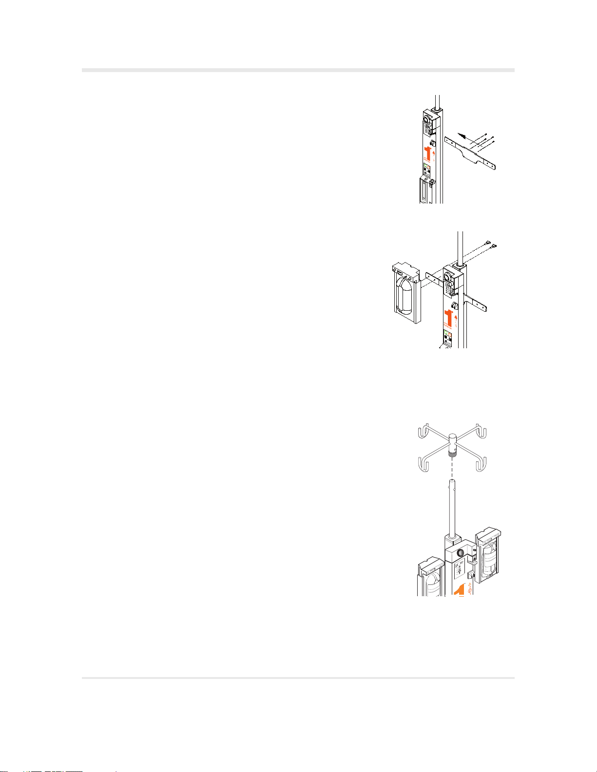
Step 3 - Install the Pressure Chambers
1Remove the four HI-2 Bracket screws located just under the Pressure
Gauge Box on the back of the Fluid Warmer and slide the HI-2
Bracket through the slot between the Fluid Warmer and the Power
Pole.
Re-install the four screws through the bracket and tighten with the
5/64" wrench supplied.
Note: Make sure the two slanted ends of the HI-2 Bracket face towards
the front of the Fluid Warmer.
2Feed the thumb screws through the back of the HI-2 Bracket and
into the HI-2 Pressure Chamber; hand tighten.
3Connect the two ends of the 1/4" black pneumatic tubing from the
Pressure Gauge Box and the Pressure Chamber to the In-Line
Pneumatic Fittings by pressing them firmly into the Pneumatic
Fittings until they can go no further.
Step 4 - Attach the Fluid Bag Hanger
1Slide the Fluid Bag Hanger on top of the pole.
2Align with tabs.
3Press down and snap into place.

SECTION 5 • Out of the Box-Assembly
Level 1®NORMOFLO®H-1129 Irrigation Fluid Warmer | Operator’s Manual 11
Step 5 - To Set Up the 3-Liter (3L) Pressure Accessory
1Disconnect the black pneumatic tubing from each In-Line Pneumatic
Fitting (b). Press on the red ring closer to the 1L pressure chamber,
and gently pull on the black tubing.
2Remove the black pneumatic tubing from the J-clips (c) on the sides
of the pole.
3Make sure the Adapter Assembly’s valve handle is in the OFF/
VENT position (d).
4Insert the black tube from the Adapter Assembly into the In-Line
Pneumatic Fitting (b).
5Connect the Adapter Assembly (g) to the 3L Pressure Cuff (f) by
connecting the male and female Luer connectors (e) securely.
6Slide the 3L Fluid Bag into the Pressure Cuff, and hang them from
the Fluid Bag Hanger.
7Repeat steps 3-6 if you are using a second 3L Pressure Cuff.
Step 6 - Disinfect the Recirculating Solution Reservoir
1Remove the fill-port plug (a) on the reservoir.
2Prepare a 0.3% hydrogen peroxide/sterile water solution for the
reservoir. Mix 140 ml of 3% hydrogen peroxide solution and 1,260 ml
of sterile water.
3Fill the reservoir with 1.4 liters of 0.3% hydrogen peroxide/ sterile
water solution.
4Replace the fill-port plug.
5Insert a Disposable Set into the Fluid Warmer.
6Insert the power cord into a properly grounded receptacle.
7Turn the Fluid Warmer ON. Let the solution circulate for a
30-minute disinfection period.
8Turn the Fluid Warmer OFF.
9Empty the reservoir.
10 Remove the Disposable Set and discard according to established
hospital procedures.
b
cc
b
de
gf
a

SECTION 5 • Out of the Box-Assembly
12 Level 1®NORMOFLO®H-1129 Irrigation Fluid Warmer | Operator’s Manual
Step 7 - Preparation for Use
1Remove the fill-port plug (a) on the front of the warming unit and
fill the reservoir to the maximum level with 1.4 liters of one of the
following solutions:
• 0.3% Hydrogen Peroxide/Sterile Water Solution: Mix 140 ml of
3% hydrogen peroxide and 1,260 ml of sterile water.
Note: If this option is selected, always use a 0.3% hydrogen
peroxide/sterile water solution when adding solution to the
reservoir.
• Distilled Water
Note: Change the recirculating solution every 30 days.
2Replace the fill-port plug.
3Lubricate O-Rings in #1 Block (b) and #2 Block (c). Place a small
amount of silicone lubricant, provided in the supplied O-Ring Kit,
on a cotton swab and apply all around the inside of each O-Ring.
Step 8 - Perform Electrical Safety Tests
Perform all applicable electrical safety tests as required per institutional
procedure. These include but are not limited to:
• Leakage current
•Hypot
•Groundbondtest
WARNING
• Grounding reliability can only be achieved when MAINS power
cords are connected to a properly grounded receptacle. Risk of
electrical shock exists if the equipment is not connected to a
properly grounded receptacle, resulting in death or serious
injury to the patient or user.
The Electrical Safety Check must be performed by qualified personnel
authorized by the institution to perform such testing. The Safety Check
must be performed and documented at least once per year, or according to
institutional policy.
a
b
c

SECTION 6 • Principle of Operation
Level 1®NORMOFLO®H-1129 Irrigation Fluid Warmer | Operator’s Manual 13
SECTION 6
Principle of Operation
The schematic illustration on the following page depicts the
Level 1®NORMOFLO®H-1129 Irrigation Fluid Warmer operations. The
primary operations are described below.
Fluid Warming
The Level 1®NORMOFLO®H-1129 Irrigation Fluid Warmer utilizes a
solution reservoir housed in a controller unit. Recirculating solution is
warmed and pumped through a heat exchanger (a part of the
Disposable Set). The solution is returned to the reservoir for
continuous recirculation and remains isolated from the patient and
from the irrigating fluid path. The recirculating solution is heated to a
pre-set temperature. The system continuously monitors and controls
the recirculating solution temperature. The Level 1®NORMOFLO®
H-1129 Irrigation Fluid Warmer is designed to stop fluid warming and
provide audible and visual alarms in the event of an over-temperature
condition.
Pressurized Fluid Delivery
The Fluid Warmer provides pressurized fluid delivery through the use
of an on-board compressor and two Pressure Chambers. The Pressure
Chambers pressurize the fluid bags for fast fluid delivery. A control
panel on each Pressure Chamber displays the pressure in the chamber.
A pressure regulator knob lets you select the desired pressure; a dial
gauge displays the selected pressure.

SECTION 6 • Principle of Operation
14 Level 1®NORMOFLO®H-1129 Irrigation Fluid Warmer | Operator’s Manual
MIN
MAX
Reservoir
Fluid
Return
Solution
Pump
Float
Switch
Pressure
Chambers
Solution
Heaters
N
O
T
F
O
R
U
S
E
W
I
T
H
A
N
Y
I
.
V
.
S
O
L
U
T
I
O
N
N
O
T
F
O
R
U
S
E
W
I
T
H
A
N
Y
I
.
V
.
S
O
L
U
T
I
O
N
N
O
T
F
O
R
U
S
E
W
I
T
H
A
N
Y
I
.
V
.
S
O
L
U
T
I
O
N
To Air Compressor
in Base
Heat
Exchanger
Irrigating Fluid Bag
Sterile Patient Line
Pressure
Gauge
H-1129H-1129
NORMOFLOW® Irrigating Fluid Warmer
Gas Vent
Pressure
Gauge Box
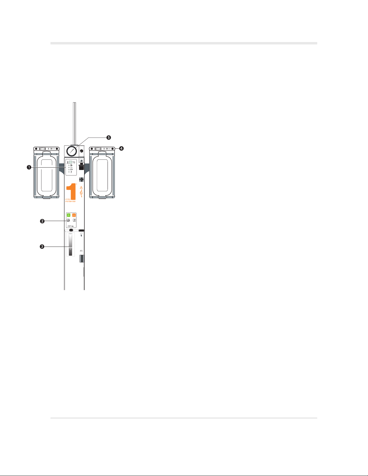
SECTION 7 • Controls and Displays
Level 1®NORMOFLO®H-1129 Irrigation Fluid Warmer | Operator’s Manual 15
SECTION 7
Controls and Displays
Five locations on the Level 1®NORMOFLO®H-1129 Irrigation Fluid
Warmer govern how the device is controlled and where function indicators
are displayed. They are called out in the figure on the facing page and
defined in the list below.
1Fluid Warmer Display Panel
2Power and Alarm Test Panel
3Reservoir Level Display
4Pressure Chamber Control Panel
5Pressure Gauge Box
The Fluid Warmer has three Interlocks, which are defined in this section.
The Interlocks detect for correct installation of a Disposable Set.
3
3
Table of contents
Other Smiths Medical Food Warmer manuals


