Smithy MIDAS MI-1220 LTD User manual

MIDAS 1220 & 1230 LTD
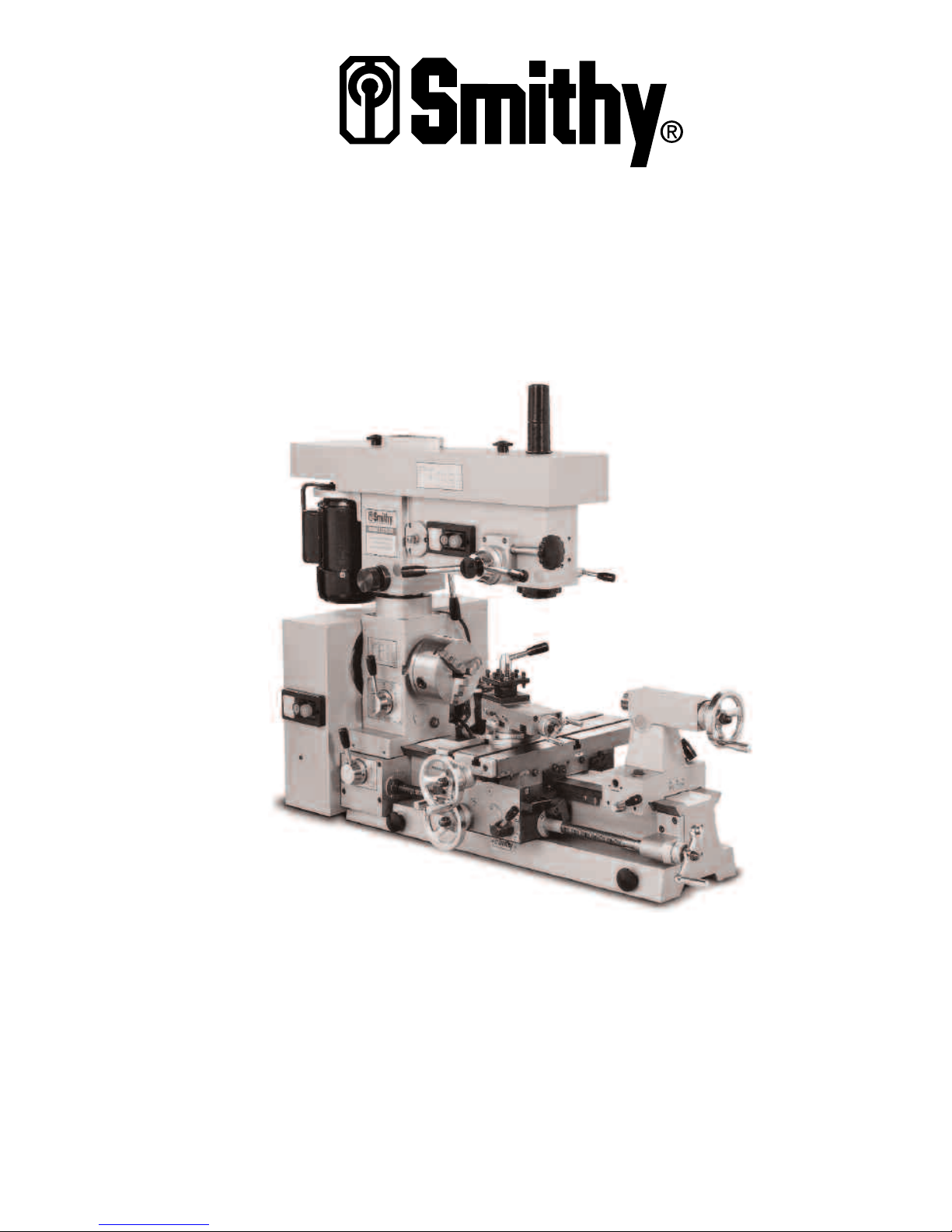
Combination Lathe - Mill - Drill
OPERATOR’S MANUAL
Updated Feb. 2019
170 Aprill Dr., Ann Arbor, MI, USA 48103
1-800-476-4849
www.smithy.com

© 2019 Smithy - All rights reserved (Revision 1).
170 Aprill Dr., Ann Arbor, Michigan, USA 48103
Toll Free Hotline: 1-800-476-4849
International: 734-913-6700
All images shown are from Midas 1220 LTD machine.
All rights reserved. No part of this manual may be reproduced or transmitted in any form by
any means, electronic, mechanical, photocopying, recording, or otherwise,
without prior written permission of Smithy Co. For information on getting permission for
While every precaution has been taken in the preparation of this manual, Smithy Co. shall not
have any liability to any person or entity with respect to any loss or damage caused or
alleged to be caused directly or indirectly by the instructions contained in this manual. Please
see section on warranty and safety precautions before operating the machine.
Printed and bound in the United States of America.

Table of Contents
Chapter 1: Introduction
Introduction . . . . . . . . . . . . . . . . . . . . . . . . . . . . . . . . . . . . . . . . . . . . . . .1-1
Chapter 2: Safety
Safety . . . . . . . . . . . . . . . . . . . . . . . . . . . . . . . . . . . . . . . . . . . . . . . . . . .2-1
Chapter 3: Caring For Your Machine
Caring for you machine . . . . . . . . . . . . . . . . . . . . . . . . . . . . . . . . . . . .3-1
Chapter 4: Basic Parts of the MI-1220 LTD
Basic Parts . . . . . . . . . . . . . . . . . . . . . . . . . . . . . . . . . . . . . . . . . . . . . . .4-1
Chapter 5: Uncrating and Setting Up the MI-1220 LTD
Moving the machine . . . . . . . . . . . . . . . . . . . . . . . . . . . . . . . . . . . . . . .5-1
Uncrating and Positioning the machine . . . . . . . . . . . . . . . . . . . . . .5-1
Millhead . . . . . . . . . . . . . . . . . . . . . . . . . . . . . . . . . . . . . . . . . . . . . . . . . .5-2
Tailstock . . . . . . . . . . . . . . . . . . . . . . . . . . . . . . . . . . . . . . . . . . . . . . . . .5-2
Three Jaw Chuck . . . . . . . . . . . . . . . . . . . . . . . . . . . . . . . . . . . . . . . . . .5-3
Selecting Location . . . . . . . . . . . . . . . . . . . . . . . . . . . . . . . . . . . . . . . . .5-3
Cleaning and Lubricating the MI-1220 LTD . . . . . . . . . . . . . . . . . . . .5-4
Oiling the Ways . . . . . . . . . . . . . . . . . . . . . . . . . . . . . . . . . . . . .5-4
Oiling the Millhead . . . . . . . . . . . . . . . . . . . . . . . . . . . . . . . . . .5-4
Oiling the Headstock . . . . . . . . . . . . . . . . . . . . . . . . . . . . . . . .5-4
Oiling the Carriage . . . . . . . . . . . . . . . . . . . . . . . . . . . . . . . . . .5-5
Oiling the Compound Angle Toolpost . . . . . . . . . . . . . . . . . .5-5
Oiling the Apron . . . . . . . . . . . . . . . . . . . . . . . . . . . . . . . . . . . .5-5
Oiling the Leadscrew . . . . . . . . . . . . . . . . . . . . . . . . . . . . . . . .5-6
Oiling the Tailstock . . . . . . . . . . . . . . . . . . . . . . . . . . . . . . . . . .5-6
Oiling the Mill/Drill Clutch . . . . . . . . . . . . . . . . . . . . . . . . . . . .5-6
Adjusting Belt Tension . . . . . . . . . . . . . . . . . . . . . . . . . . . . . . . . . . . . .5-7
Mill . . . . . . . . . . . . . . . . . . . . . . . . . . . . . . . . . . . . . . . . . . . . . . . . . . .5-7

Lathe . . . . . . . . . . . . . . . . . . . . . . . . . . . . . . . . . . . . . . . . . . . . . . . . . . .5-7
Adjusting Gibs . . . . . . . . . . . . . . . . . . . . . . . . . . . . . . . . . . . . . . . . . . . .5-7
Reducing Backlash . . . . . . . . . . . . . . . . . . . . . . . . . . . . . . . . . . . . . . . .5-8
Running in the MI-1220 LTD . . . . . . . . . . . . . . . . . . . . . . . . . . . . . . . . .5-8
Millhead Run in . . . . . . . . . . . . . . . . . . . . . . . . . . . . . . . . . . . . .5-8
Lathe Run in . . . . . . . . . . . . . . . . . . . . . . . . . . . . . . . . . . . . . . . .5-9
Setting Lathe and Mill Speeds for the MI-1220 LTD . . . . . . . . . . .5-10
Chapter 6: Turning
Turing Speeds . . . . . . . . . . . . . . . . . . . . . . . . . . . . . . . . . . . . . . . . . . . .6-1
Gear Ratios . . . . . . . . . . . . . . . . . . . . . . . . . . . . . . . . . . . . . . . . . . . . . . .6-3
Chapter 7: Metal Theory
Tool Sharpness . . . . . . . . . . . . . . . . . . . . . . . . . . . . . . . . . . . . . . . . . . .7-1
Heat . . . . . . . . . . . . . . . . . . . . . . . . . . . . . . . . . . . . . . . . . . . . . . . . . . .7-1
Chapter 8: Grinding Cutter Bits for Lathe Tools
High Speed Steel Cutters . . . . . . . . . . . . . . . . . . . . . . . . . . . . . . . . . . .8-1
Materials Other than Steel . . . . . . . . . . . . . . . . . . . . . . . . . . . . . . . . . .8-3
Bits for Turning and Machining Brass . . . . . . . . . . . . . . . . . . . . . . . .8-3
Special Chip Craters and Chipbreakers . . . . . . . . . . . . . . . . . . . . . . .8-4
Using a Center Gauge to Check V-Thread Forms . . . . . . . . . . . . . .8-4
Acme or Other Special Threads . . . . . . . . . . . . . . . . . . . . . . . . . . . . .8-5
Carbide-Tipped Cutters and Cutter Forms . . . . . . . . . . . . . . . . . . . . .8-5
Chapter 9: Setting Up Lathe Tools
Cutting Tool Height . . . . . . . . . . . . . . . . . . . . . . . . . . . . . . . . . . . . . . . .9-1
Turning Tools . . . . . . . . . . . . . . . . . . . . . . . . . . . . . . . . . . . . . . . . . . . . .9-1
Threading Tools . . . . . . . . . . . . . . . . . . . . . . . . . . . . . . . . . . . . . . . . . . .9-2
Cutoff, Thread Cutting and Facing Tools . . . . . . . . . . . . . . . . . . . . . .9-3
Boring and Inside Threading Tools . . . . . . . . . . . . . . . . . . . . . . . . . .9-3
Chapter 10: Setting Up with Centers, Collets and Chucks
Centering . . . . . . . . . . . . . . . . . . . . . . . . . . . . . . . . . . . . . . . . . . . . . . . .10-1
Mounting Work between Centers . . . . . . . . . . . . . . . . . . . . . . . . . .10-3
Using a Clamp Dog . . . . . . . . . . . . . . . . . . . . . . . . . . . . . . . . . . . . . . .10-4
Using Faceplates . . . . . . . . . . . . . . . . . . . . . . . . . . . . . . . . . . . . . . . . .10-4
Setting Up Work on Mandrel . . . . . . . . . . . . . . . . . . . . . . . . . . . . . . .10-5
Steady Rest and Follow Rest . . . . . . . . . . . . . . . . . . . . . . . . . . . . . . .10-6
Steady Rest . . . . . . . . . . . . . . . . . . . . . . . . . . . . . . . . . . . . . . .10-6
Follow Rest . . . . . . . . . . . . . . . . . . . . . . . . . . . . . . . . . . . . . . .10-7

Setting Up Work in a Chuck . . . . . . . . . . . . . . . . . . . . . . . . . . . . . . . .10-7
Mounting Work in a Four-Jaw Independent
Lathe Chuck . . . . . . . . . . . . . . . . . . . . . . . . . . . . . . . . . . . . . . .10-8
Mouting Work in a Three-Jaw Universal Chuck . . . . . . .10-9
Toolpost Grinders . . . . . . . . . . . . . . . . . . . . . . . . . . . . . . . . . . . . . . .10-11
Chapter 11: Lathe Turning
Rough Turning . . . . . . . . . . . . . . . . . . . . . . . . . . . . . . . . . . . . . . . . . . .11-1
Finish Turning . . . . . . . . . . . . . . . . . . . . . . . . . . . . . . . . . . . . . . . . . . . .11-2
Turning to Shapes . . . . . . . . . . . . . . . . . . . . . . . . . . . . . . . . . . . . . . . .11-2
Machining Square Corners . . . . . . . . . . . . . . . . . . . . . . . . . . . . . . . .11-3
Finishing and Polishing . . . . . . . . . . . . . . . . . . . . . . . . . . . . . . . . . . . .11-3
Taper Turning . . . . . . . . . . . . . . . . . . . . . . . . . . . . . . . . . . . . . . . . . . . .11-4
Chapter 12: Lathe Facing and Knurling
Facing Across the Clutch . . . . . . . . . . . . . . . . . . . . . . . . . . . . . . . . . .12-1
Knurling . . . . . . . . . . . . . . . . . . . . . . . . . . . . . . . . . . . . . . . . . . . . . . . . .12-2
Chapter 13: Cutting Off or Parting with a Lathe
Cutting Off or Parting with a Lathe . . . . . . . . . . . . . . . . . . . . . . . . . .13-1
Chapter 14: Lathe Drilling and Boring
Lathe Drlling . . . . . . . . . . . . . . . . . . . . . . . . . . . . . . . . . . . . . . . . . . . . .14-1
Reaming . . . . . . . . . . . . . . . . . . . . . . . . . . . . . . . . . . . . . . . . . . . . . . . . .14-1
Boring . . . . . . . . . . . . . . . . . . . . . . . . . . . . . . . . . . . . . . . . . . . . . . . . . .14-2
Cutting Internal Threads . . . . . . . . . . . . . . . . . . . . . . . . . . . . . . . . . . .14-3
Cutting Special Form Internal Threads . . . . . . . . . . . . . . . . . . . . . .14-4
Chapter 15: Changing Gears on Your MI-1220 LTD
Changing Gears . . . . . . . . . . . . . . . . . . . . . . . . . . . . . . . . . . . . . . . . . .15-1
Chapter 16: Cutting Threads on Your MI-1220 LTD
Threading Terms . . . . . . . . . . . . . . . . . . . . . . . . . . . . . . . . . . . . . . . . .16-1
Cutting Right Hand Threads . . . . . . . . . . . . . . . . . . . . . . . . . . . . . . . .16-3
Using the Threading Dial . . . . . . . . . . . . . . . . . . . . . . . . . . . . . . . . . .16-4
Cutting Multiple Threads . . . . . . . . . . . . . . . . . . . . . . . . . . . . . . . . . .16-5
What Not To Do When Cutting Threads . . . . . . . . . . . . . . . . . . . . .16-5
Finishing Off a Threaded End . . . . . . . . . . . . . . . . . . . . . . . . . . . . . . .16-5
Cutting Threads on a Taper . . . . . . . . . . . . . . . . . . . . . . . . . . . . . . . .16-5

Chapter 17: Milling
Milling . . . . . . . . . . . . . . . . . . . . . . . . . . . . . . . . . . . . . . . . . . . . . . . . . .17-1
Holding Milling Cutters . . . . . . . . . . . . . . . . . . . . . . . . . . . . . . . . . . . .17-2
Arbors . . . . . . . . . . . . . . . . . . . . . . . . . . . . . . . . . . . . . . . . . . . . . . . . . .17-2
Collets and Holders . . . . . . . . . . . . . . . . . . . . . . . . . . . . . . . . . . . . . . .17-2
Adaptors . . . . . . . . . . . . . . . . . . . . . . . . . . . . . . . . . . . . . . . . . . . . . . . .17-3
Milling Cutters . . . . . . . . . . . . . . . . . . . . . . . . . . . . . . . . . . . . . . . . . . .17-4
End Mill Cutters . . . . . . . . . . . . . . . . . . . . . . . . . . . . . . . . . . . . . . . . . .17-4
Plain Milling Cutters . . . . . . . . . . . . . . . . . . . . . . . . . . . . . . . . . . . . . .17-6
Side Milling Cutters . . . . . . . . . . . . . . . . . . . . . . . . . . . . . . . . . . . . . . .17-6
Slitting Saws . . . . . . . . . . . . . . . . . . . . . . . . . . . . . . . . . . . . . . . . . . . . .17-6
Angle Milling Cutters . . . . . . . . . . . . . . . . . . . . . . . . . . . . . . . . . . . . . .17-7
Form Relieved Cutters . . . . . . . . . . . . . . . . . . . . . . . . . . . . . . . . . . . . .17-7
Flycutters . . . . . . . . . . . . . . . . . . . . . . . . . . . . . . . . . . . . . . . . . . . . . . . .17-7
Using Cutting Fluid . . . . . . . . . . . . . . . . . . . . . . . . . . . . . . . . . . . . . . . .17-8
Tool Grinding . . . . . . . . . . . . . . . . . . . . . . . . . . . . . . . . . . . . . . . . . . . .17-8
Speeds and Feeds for Milling . . . . . . . . . . . . . . . . . . . . . . . . . . . . . .17-8
Feeds . . . . . . . . . . . . . . . . . . . . . . . . . . . . . . . . . . . . . . . . . . . . . . . . . .17-9
Up Milling . . . . . . . . . . . . . . . . . . . . . . . . . . . . . . . . . . . . . . . . . . . . . . .17-9
Down Milling . . . . . . . . . . . . . . . . . . . . . . . . . . . . . . . . . . . . . . . . . . . .17-10
Common Milling Operations . . . . . . . . . . . . . . . . . . . . . . . . . . . . . . .17-12
Milling Flat Surfaces . . . . . . . . . . . . . . . . . . . . . . . . . . . . . .17-12
Squaring a Workpiece . . . . . . . . . . . . . . . . . . . . . . . . . . . . .17-12
Milling a Cavity . . . . . . . . . . . . . . . . . . . . . . . . . . . . . . . . . . .17-13
Tapping . . . . . . . . . . . . . . . . . . . . . . . . . . . . . . . . . . . . . . . . . .17-13
Chapter 18: Workholding
Mounting to the Table . . . . . . . . . . . . . . . . . . . . . . . . . . . . . . . . . . . . .18-1
Using a Vise . . . . . . . . . . . . . . . . . . . . . . . . . . . . . . . . . . . . . . . . . . . . .18-1
Dividing Heads . . . . . . . . . . . . . . . . . . . . . . . . . . . . . . . . . . . . . . . . . . .18-2
Rotary Tables . . . . . . . . . . . . . . . . . . . . . . . . . . . . . . . . . . . . . . . . . . . .18-2
Chapter 19: Troubleshooting
Powerfeed and Thread Cutting . . . . . . . . . . . . . . . . . . . . . . . . . . . . .19-1
Carriage and Milling Table . . . . . . . . . . . . . . . . . . . . . . . . . . . . . . . . .19-2
Lathe Turning . . . . . . . . . . . . . . . . . . . . . . . . . . . . . . . . . . . . . . . . . . . .19-3
Milling . . . . . . . . . . . . . . . . . . . . . . . . . . . . . . . . . . . . . . . . . . . . . . . . . .19-4
Drilling . . . . . . . . . . . . . . . . . . . . . . . . . . . . . . . . . . . . . . . . . . . . . . . . . .19-4
Drive System . . . . . . . . . . . . . . . . . . . . . . . . . . . . . . . . . . . . . . . . . . . . .19-5
Chapter 20: Removing the Quill and Quill Feed Assembly
Steps . . . . . . . . . . . . . . . . . . . . . . . . . . . . . . . . . . . . . . . . . . . . . . . . . .20-1
Assembly . . . . . . . . . . . . . . . . . . . . . . . . . . . . . . . . . . . . . . . . . . . . . . . .20-2


Chapter 1
Introduction
Congratulations on purchasing a Smithy lathe-mill-drill. We are pleased you chose Smithy
to fulfill your machining needs.
The purpose of this manual is to give the machinist, beginning or advanced, the
information he need to operate the Smithy Midas 1220 LTD. It will teach you about the
machine’s parts and how to care for them. We’ll explain how to grind cutters, set up lathe
tools, hold work pieces, and do all basic machining operations.
Please read this operator’s manual carefully. If you don’t understand how your machine
works, you may damage it, your project, or yourself. If you want to learn more about
machining practices, Smithy offers books that meet the needs of machinists at all levels
of experience. We also suggest using your local library as a resource. Enrolling in a
machining class will give you the best knowledge of machining.
If you have any questions not covered in this manual, please call Smithy. Our trained
technicians will help you with any machining problems you may have. Dial our toll free
number 1-800-476-4849 Monday through Friday, 8:00 am to 5:00pm Eastern Time. You
can also find Smithy on the Internet at www.smithy.com. Check for service updated and
service bulletins.
We are always interested in your suggestions to improve our products and services. Feel
about this operator’s manual, or if you have a project you’d like to share with other Smithy
owners, contact Smithy Co., PO Box 1517, Ann Arbor, Michigan 48106-1517.
We look forward to a long working relationship with you. Thank you again for putting your
trust in Smithy.
This manual should remain with your Smithy machine. If ownership changes, please
include the owner’s manual with the machine.
Model No.:__________________________________________________
Serial No.:__________________________________________________
(at the back of the lathe bed)
Purchase Date:______________________________________________
Delivery Date:_______________________________________________
Sales Technician:____________________________________________
1-1
Or Visit www.smithy.com

Chapter 2
Safety
Your workshop is only as safe as you make it. Take responsibility for the safety of all who
use or visit it. This list of rules is by no means complete, and remember that common
sense is a must.
1. Know your machine. Read this manual thoroughly before attempting to operate your
machine. Don’t try to do more than you or your machine can handle. Understand the
hazards of operating a machine tool. In particular, remember never to change speeds or
set-ups until the machine is completely stopped, and never operate it without first rolling
your sleeves or tying them at your wrists.
2. Ground the machine. The MI-1220 LTD has three-conductor cords and three-prong
grounding-type receptacles. Never connect the power supply without properly grounding
the machine.
3. Remove all adjusting keys and wrenches from the machine before operating. A chuck
key or misplaced Allen wrench can be safety hazard.
4. Keep your work area clean and organized. Cluttered work areas and benches invite
accidents. Have a place for everything and put everything in place.
5. Keep children away from the machine while it is in use. Childproof your shop with
padlocks, master switches, and starter keys, or store the machine where children do not
have access to it.
6. Wear appropriate clothing. Avoid loose-fitting clothes, gloves, neckties, or jewelry that
could get caught in moving parts. If you have long hairs, tie it up or otherwise keep it
from getting into the machine.
7. Use safety glasses, goggles, or a face shield at all times. Use glasses designed for
machinery operation; regular glasses will not do. Have extras for visitors. Know when to
wear a facemask and earplugs, as well.
8. Check for damaged parts. Make sure the machine will run properly before operating it.
9. Disconnect the machine before servicing and when changing accessories. Shut power
off before making changes, removing debris, or measuring your work. Don’t reach over
the machine when it’s operating. Keep your hands out of the way.
10. Avoid accidental starts. Turn the switch to OFF before plugging in the machine.
11. Secure your work. Flying metal is dangerous. Loose work can also bind tools.
12. Use the recommended accessories. Understand how to use them before trying them
out.
2-1 For Assistance: Call Toll Free 1-800-476-4849

13. Use the correct tool for the job. Don’t try to make a tool into something it isn’t.
14. Keep your mind on your work. Pay attention to these simple rules and you will spend
many safe, enjoyable houses in your workshop.
Note: Your safety depends largely on your practices.
2: Safety
2-2
Or Visit www.smithy.com

Chapter 3
Caring For Your Machine
Your machine is a delicate, precision tool with hardened ways and hand-scraped bearing
surfaces under the table and carriage. Any rust spot or battering of the ways, any chips
or grit between close-fitting parts, will affect the accuracy of this fine tool. Follow these
guidelines whenever you use your Smithy machine:
1. When you finish working, wipe machined surfaces with a clean, oily rag. Never leave
the machine without this thin film of protective oil all over parts that might rust,
especially ground finished parts.
2. Never lay wrenches, cutting tools, files, or other tools across the ways of your lathe.
The slightest dent or burr will impair its accuracy.
3. Before inserting collars, centers, adapters, or drawbar attachments in either the
spindle or tailstock spindle, wipe them a clean, oily rag. Also, wipe all internal surfaces
carefully with an oily rag on a ramrod. Chips or dirt on the centers or in the spindle nose
can scratch or mark surfaces and interfere with the assembled part’s alignment.
4. Lubricate the machine before each use as seen on Section 5.4.
5. Use good 10W 30 weight non-detergent oil on your machine.
6. Cover your machine to protect it from dust and moisture.
Note: An old machinist trick is to leave camphor in the toolbox and on the machine to
prevent rust. Newer compounds that also protect machines that will unused for some
time are BoeShield, developed by the Boeing Company and CRC Lubricants. There are
also specialty oils that may be purchased.
3-1 For Assistance: Call Toll Free 1-800-476-4849

Chapter 4
Basic Parts of the MI-1220 LTD
Learn the operation of your machine, you have to know the names and functions of its
basic units.
Figure 4.1 Midas 1220 LTD
1. Bed. The bed is the machine’s foundation. It is heavy, strong, and built for absolute
rigidity. The two ways on the top are the tracks on which the carriage and tailstock
travel. To maintain an exact relationship between tool point and work piece from one end
of the machine to the other, the ways must be absolutely true and accurately aligned to
the line of centers and to one other.
2. Carriage. The carriage consists of the saddle and apron. It moves by hand or power
along the bed, carrying the cross slide, compound rest, and toolpost. Its function is to
support the cutting tool rigidity and move it along the bed for different operations. It locks
into place by tightening the carriage lock with the setscrew on the backside of the
carriage.
1
2
34
5
6
7
8
9
10 11
12
13
14
15
16
17
18
4-1
Or Visit www.smithy.com

3. Compound Rest. Mounted on the cross slide, the compound rest swivels to any angle
horizontal to the lathe axis to produce bevels and tapers. Cutting tools fasten to a
toolpost on the compound rest. The calibration on the front of the base are numbered in
degrees from 60 right to 60 left.
4. Cross Slide. The T-slotted cross slide moves crosswise 90 degrees to the lathe axis by
manual turning of the cross feed screw hand wheel. It also serves as the milling table.
5. Drill Press and Fine Feed Clutch. Pushing in the drill press clutch (engages the fine
feed). To work the clutch, release the spring tension by rotating the drill press handles
clockwise. Pull the clutch out to sue it as a drill press or push it in to use the fine feed.
Use the fine fee hand wheel to move the quill up and down.
6. Forward/OFF/Reverse Switch. This is the main switch used to operate the lathe. It is
simply a forward/reverse switch for the motor. The motor turns counterclockwise for
normal lathe operation and clockwise for normal milling and drilling operation. The
MI-1220 LTD has two switches, one located on the millhead and one on the right side of
the gearbox.
7. Gearbox. The gearbox houses the belts that derive the spindle and change gears for
the powerfeed. Select the thread pitch (for threading) or the feed rate (for turning) by
changing the four change gears on the right side of the gearbox.
8. Headstock. The headstock, which is secured to the bed, houses the gears the drive
the powerfeed and the taper that secure the lathe spindle.
9. Lathe Spindle. The end of the lathe spindle facing the tailstock is the spindle nose. The
spindle nose, which has an MT4 taper, rotates the work piece and drives the lathe chicks
and other workholding devices. All attachments (like three-jaw chucks, four-jaw chucks,
faceplates, etc.) bolt to the spindle flange either directly or via an adapter plate.
10. Leadscrew. The leadscrew, which runs the length of the bed, moves the carriage for
lathe turning or thread cutting. It works both manually and under power. You can also
use it manually with the mill.
11. Locks. Locks on the cross slide, carriage, quill, and tailstock (two) keep them from
moving. During machining, lock all axes except the one you want to move.
12. Micrometer Control and Calibration. Just inside the handles of the tailstock
crossfeed, drill calibrated in millimeters. The compound feed and crossfeed are
calibrated in two thousandths, the tailstock in thousandths, the leadscrew in two
thousandths, and the drill press in forty thousandths.
Note: These micrometer dial collars can move independently around the handle shafts.
This independent motion is called float. The MI-1220 LTD has floating dials on the cross
slide, tailstock, longitudinal and mill feeds. They let you zero the collars at any point and
read the feed travel from that point on the dial for increased accuracy.
13. Mill Spindle. The mill spindle attaches to the quill, which moves in and out of the
head. The quill lock keeps the quill still when you install or remove tools from it and while
milling horizontally. Usually, tools fir into collets that attach through the spindle via
drawbars.
Midas 1220 LTD Operator’s Manual
4-2 For Assistance: Call Toll Free 1-800-476-4849

14. Half-nut Lever. This lever transmits power to the carriage for threading.
15. Power Longitudinal Feed. Push the lever down to engage the power of the long feed
for general cutting.
16. Power Cross Feed. Push the lever down to engage the cross feed and pull it up to
disengage.
17. Powerfeed Speed Selector. The two-speed selector for powering the leadscrew is on
the front of the headstock. The leadscrew turns twice as fast in the II position as in the
I position.
18. Tailstock. The tailstock, which provides right-end support for the work, moves along
the bed and can stop at any point on it. It holds centers, drills, reamers, taps, and other
tools. To move the tailstock spindle, which has an MT3 taper, turn the tailstock hand
wheel. The scale of offset calibrations on the back of the tailstock is in millimeters.
Note: To offset the tailstock, loosed the four base locking bolts. To offset to the left,
loosed the left adjusting bolt and tighten the right and do the same on the other side
when you want to offset to the right. See figure. 4.2.
Figure 4.2 Tailstock base locking bolts.
Setover
Screw
Rgiht
Treslte
Setscrew
4: Basic Parts o thef Midas 1220 LTD
4-3
Or Visit www.smithy.com

Chapter 5
Uncrating and Setting Up the MI-1220 LTD
Moving the Machine
Moving a machine tool can be dangerous. Improper techniques and methods may injure
you and/or damage the machine. To find a professional to move and site your Smithy
machine, look in your local Yellow Pages under “Machine Tools, Moving and/or Rigging”.
If there is no such listing or your community does not have a rigging specialist, a local
machine shop or machinist may be able to provide referral.
When you pick up the machine at the shipping terminal, bring a crowbar, tin snips for
cutting the metal straps, and a hammer. If there is obvious shipping damage to the crate,
you’ll be able to inspect the machine before signing for it. Note any damage on the bill
of lading (shipping document). Fill out the claims forms and notify both Smithy Co. and
the shipping terminal about the damage. Failure to notify both parties can complicate
and/or invalidate a claims process.
Trucking company terminals usually have forklifts to assist customers. It’s most
convenient to transport the machines in trucks without canopies and large vans.
Uncrating and Positioning the Machine
Figure 5.1 Tip the crate from the tailstock end up and over the machine.
The machine is assembled, inspected, and ready to do in its stand. It’s wrapped in a water
and greaseproof cover, strongly braced, and crated. A box of accessories is also in the
crate.
The metal bands that encircle the crate are under tension. Wearing eye protection and
gloves, cut the metal bands with tin snips.
5-1 For Assistance: Call Toll Free 1-800-476-4849

Caution
The cut edges are sharp. The bands secure the crate top to the base.
After removing the straps, lift off the crate top. Tip the crate from the tailstock end up
and over the machine (Figure 5.1). Do not damage the crate. You may need it another
time to transport the machine.
Once your crate cover is removed it is time to put your machine on its bench. The
machine is just less than 500 pounds so make sure you have some extra hands to help.
There are four lifting pints that pull out from the bed of the lathe. You can use chains or
a tow rope to wraparound these pins and the aid of a lifting device such as an engine
hoist to list the machine on to a bench rated to support the machine’s weight.
Without a mechanical device to aid in your lifting you can lighten the machine by
removing a few or all of the following:
Millhead
1. Remove the four hexagon socket-head screws at the base of the millhead support
column. If a screw runs through the belt box into the flange of the support column,
remove it too.
2. Lock the millhead-locking handle.
3. Lift the millhead and column off the lathe head. You may have to rock it back and forth
while lifting it. Make sure that the mill head is locked to the column before removing the
millhead.
Tailstock
1. Loosen the tailstock lock and pull the tailstock off the end of the bed. The gib and
locking pin will fall out. Be careful no to lose them.
Figure 5.2 The chuck attaches to the spindle flange with three bolts.
The one bolt located on the other side of the spindle does not show.
Bolts
5: Uncrating and Setting Up the MI-1220 LTD
5-2
Or Visit www.smithy.com

Three-Jaw Chuck
1. Remove the three bolts behind the chuck that hold it to the spindle flange (Figure 5.2).
The chuck will come off. Don’t let it fall onto the ways. Placing a board between the chuck
and ways will protect the ways.
Place the machine on a strong, rigid table 40” long, 24” wide and 28” to 33” high. We
recommend you to bolt down the MI-1220 LTD machine using the holes in the base of
the bed or using the lifting handles as they held the machine to the shipping pallet.
Selecting a Location
There are several major considerations for selecting a location for your Smithy.
Operation is from the apron side, so allow at least 40” to 48” clearance in front of the
machine.
The machine should be on a 20-amp circuit, positioned as close as possible to the power
supply. Try not to use an extension cord. If you must use one, check with an electrician
about the proper size.
Provide ample working light over the operator’s shoulder.
Figure 5.3 Check along and across the bed to make sure it is level.
Place the machine on a solid foundation, concrete if possible. If you must put it on a
wood floor, make sure it is adequate. Brace it if necessary to prevent sagging or settling.
Make allowances at the back of the machine tool as at its end and above it for later
additions, attachments, and/or accessories. Provide clearance on the left end for bar
stock to be fed through the spindle. If you are considering placing more than one machine
in an area, allow enough floor space to feed long bar stock to each machine.
Notice To check bench and bed level accuracies,
successively place level at A, B, C, D
(longitudinal positions) and E and F (transverse
positions). Bedways alignment in the longitudinal place
should be better than 0.0016/40”; alignment in the
traverse plane should be better than 0.0024/40”.
Midas 1220 LTD Operator’s Manual
5-3 For Assistance: Call Toll Free 1-800-476-4849

Cleaning and Lubricating the MI-1220 LTD
Smithy machines are shipped with protective grease coating called cosmoline. Use
WD-40 or non-corrosive kerosene to remove the cosmoline.
Once you have your MI-1220 LTD set up and positioned correctly, you are ready for
lubricating. You must do this carefully and thoroughly before starting the machine. Use a
pressure oil can and a supply of good quality SAE No.10 weight oil.
To be thorough and complete, follow this routine:
Oiling the Ways
Run the carriage as far to the left as possible. Put a few
drops of oil on the ways. Run the carriage to the extreme
right and repeat. You may want to use Way Lube, special
oil formulated for the ways.
Oiling the Millhead Quill
Using your mill handles or your fine feed crank to lower
the millhead down. Apply a thin layer of oil to the quill and
work it down and up until it runs smoothly.
Oiling the Headstock
Figure 5.6 Oil the button behind the D gear.
Figure 5.4 Oiling the ways
Figure 5.5 Oiling the
Millhead Quill
5: Uncrating and Setting Up the MI-1220 LTD
5-4
Or Visit www.smithy.com

Open the gearbox door to expose the pick-off gears. Oil the button in the casting behind
the D gear. Then put a few drops of oil on the teeth of all the gears. Grease the zerk on
the A gear shaft.
Check the sight glass under the chuck. If necessary, add oil until it is half full. The oil fill
plug is at the back of the headstock above the motor. Be careful not to overfill it. The
gearbox requires only 8 to 10 ounces of oil.
Oiling the Carriage
Lubricate the oil buttons in the cross feed table.
There are two buttons on the left of the saddle for
the bedways and two on the front of the cross slide
for the cross slide ways.
Oil the button in the center of the cross slide.
Put a few drops of oil on the compound slides.
Oiling the Compound Angle Toolpost
Figure 5.8 Oil the buttons along the cross feed table.
Oil two buttons on top of the compound angle toolpost.
Oiling the Apron
Put oil in the button just behind the cross slide hand wheel.
Figure 5.7 Oiling the table
Midas 1220 LTD Operator’s Manual
5-5 For Assistance: Call Toll Free 1-800-476-4849

Put oil on the button at the back of the cross slide.
Oiling the Leadscrew
Put oil in the oil buttons on the left trestle.
Put oil in the support for the right end of the leadscrew.
Oiling the Tailstock
Figure 5.9 Oil the two buttons on the top of the tailstock.
Oil the buttons on top of the tailstock.
Oiling the Mill/Drill Clutch
Figure 5.10 Oil the clutch housing button.
Put oil in the button on top of the clutch housing.
Notice
To keep your machine in peak condition, lubricate it daily after removing any debris.
Do not fill the gearbox sight glass more than half way. Too much oil will make the
motor lug and sling oil out form behind the chuck and inside the belt box.
5: Uncrating and Setting Up the MI-1220 LTD
5-6
Or Visit www.smithy.com
This manual suits for next models
1
Table of contents
Popular Industrial Equipment manuals by other brands

joule
joule Cyclone Installation & maintenance manual

SCHUNK
SCHUNK PZV Assembly and operating manual

Acoustic Signature
Acoustic Signature TA-2000 instruction manual

KTR
KTR DATAFLEX 85 Series Operating & assembly instructions

Sundstrom
Sundstrom SR 507 Instructions for use

BOWMAN
BOWMAN MINI GAME TRAILER instructions