Smoke Factory ENTERPRISE TC4 User manual

SMOKE FACTORY
FOG & HAZE GENERATORS
ENTERPRISE TC4
SERVICE MANUAL
ATTENTION
!
Testing under 110-230V can be a danger for life.
The testing person should be a technical skilled
person to avoid injuries!

2ENTERPRISE TC4 – SERVICE MANUAL
SMOKE FACTORY
FOG & HAZE GENERATORS
1. Introduction
1.1 General
This document should be used if ENTERPRISE TC4 is not working properly. With this document it
should be possible to find the fault/ not working device and change this device without the direct help
of the manufacturer.
ENTERPRISE TC4 has two pumps and thermocouples (2400W heater) and a connector for an
external fan. ENTERPRISE TC4 is available for 230V/50Hz.
1.2 Danger
-While replacing any device the power plug should be unplugged.
-While testing under life conditions (230V), never touch blank contacts.
2. Components
2.1 Pump EX5 230V/50Hz (50172), 120V/60Hz (59019)
Picture 2.1: Pump EX5 230V/50Hz (50172)
2.2 HE 2400 Heat Exchanger (part number 69022)
Picture 2.2.1b: Power connection
Picture 2.2.1a: HE2400 Heat Exchanger – ENTERPRISE TC4 (69022)
Th
e
rm
ostat
X1:3 X1:6

2.3 Circuit Boards
There are two boards: the PCB ENTERPRISE TC4 and the PCB Remote (DMX and analogue).
2.3.1 PCB ENTERPRISE TC4 (part number 39003)
Picture 2.3.1a: PCB ENTERPRISE TC4 – Top view (39003)
Picture 2.3.1d: Fuse on PCB ENTERPRISE TC4 board
Picture 2.3.1c: PCB ENTERPRISE TC4 – Bottom view
2.3.2 PCB Remote (DMX and analogue) (part number 39004)
Picture 2.3.2: PCB Remote (39004)
PCB
Power
Connector for
thermocouple
Power
terminal for
the fan
Solder
pads for
triac
Terminal block
ENTERPRISE TC4 – SERVICE MANUAL 3
SMOKE FACTORY
FOG & HAZE GENERATORS

2.4 Fuse holder IP67 (part number 40056)
Picture 2.4: Fuse holder (40056)
3. Diagrams
3.1 Part list ENTERPRISE TC4
Fuse holder
Connector for external fan
4ENTERPRISE TC4 – SERVICE MANUAL
SMOKE FACTORY
FOG & HAZE GENERATORS

ENTERPRISE TC4 – SERVICE MANUAL 5
SMOKE FACTORY
FOG & HAZE GENERATORS
ENTERPRISE TC4

6ENTERPRISE TC4 – SERVICE MANUAL
SMOKE FACTORY
FOG & HAZE GENERATORS

3.2 Wire plan
Pumps
PCB ENTERPRISE TC4
(Top view, see
picture 2.1a)
1
2
3
4
5
6
X1
Fuse
Power
connection
for the fan
(External)Thermal
trip
Green/ yellow
(Ground)
Heater
(Top view)
Thermocouple
XLR PCB
Wirepl.ENTERPRISE TC4
X
1:1 Pumps (2x yellow)
X
1:2 Pumps (2x black)
X
1:3 Heat Catridge (1x red)
X
1:4 Power Supply
X
1:5 Power Supply
X
1:6 Heat Catridge (1x white/yellow)
Flat cable 6-pin
A
A
A
B
B
T
hermostat
Fog nozzle
2 13
Fuse
Where
appropriate
capacitor else
open
1 brown
2 black
3 blue
White
Green
WhiteGreen
ENTERPRISE TC4 – SERVICE MANUAL 7
SMOKE FACTORY
FOG & HAZE GENERATORS

3.3 Fluid circuit (Photograph)
Picture 3.3a: Fluid circuit – one side
Picture 3.3b: Fluid circuit – second side
The fog fluid is coming from the fluid bottle [1]. It is flowing to the two pumps [2]. Coming out of the
pumps the fluid is flowing via the pressure pipes to the HE. There it will be heated up and leaves the
exit as fog [4].
[1] Fluid
income from
fluid bottle
Fluid income
from fluid
bottle [1]
[2] To the
pumps
[2] To the
pumps
[3] Out of the
pumps, to
the HEs
[4] Fog exit
8ENTERPRISE TC4 – SERVICE MANUAL
SMOKE FACTORY
FOG & HAZE GENERATORS

4. Faults
First Step:
Open the unplugged unit. Plug the unit in; check the display. Start the ENTERPRISE TC4 unit and check if there is fog or not. If so check the consistency (not
wet) and the smell (not pungent) of the fog. It can take a while before the unit is working normal because of unsteady fluid leavings in the tubes. First listen if the
fluid pumps start, is fluid escaped somewhere, does the heat exchanger heat up, maybe there is an apparent fault. Be careful because of the 230V and
the heat. Is the defect part apparent, have closer look to this and do the testing as described in the appropriate chapter below. Is it more difficult to locate the
fault,follow the steps in the table below.
4.1 Description of general faults
No. Fault Identification Testing Result Repair
1.1 PCB ENTERPRISE TC4:
1.1.1 Check the power connection at the board (PIN
X1:4/5)
Power
No Power
Proceed with 1.2
Exchange the board
1.1.2 Check the fuse, continuity test No continuity
Continuity
Exchange the fuse
Proceed with 1.3
1. No power
after plugging
in of the
power supply.
Display remains
dead
1.1.3 Check if something is burned at the board Burned
Not burned
Exchange the board
Check if there is fluid/ humidity, if so dry
carefully
2.1 Check the pumps, maybe one or both are
broken (see test plan below)
One is not working
Both are working
Change the broken device
Proceed with 2.2
2.2 Check the heat exchanger, maybe it is/ they are
clogged or partial clogged (see test plan below)
One is not working
Both are working
Change the broken device
Proceed with 2.3
2.3 Check the tube connections/fittings, maybe one
is disconnected
Everything is connected properly
Some tubes are disconnected
Proceed with 2.4
Reconnect the disconnected tubes
2. Power
available, less
fog/ approx.
the half or no
fog
Display is ok but no
„normal“ fog/ less
fog or no fog.
2.4 Check the fog fluid, maybe it's nearly empty Fog fluid is sufficient available
Fog fluid is almost empty
Check the power supply (see test plan
below)
Change the fog fluid bottle
3. Various faults:
E4, wet fog,
overheat,
wrong display,
etc.
Unit is wet from the
inside with fog
fluid, boards are
wet
This fault is apparent, no testing is necessary.
Take machine to pieces and clean each component!
Heater is leaking internally
Cooling air was to foggy
Broken pressure pipe
The heater needs to be changed.
Change location
Change pipe
ENTERPRISE TC4 – SERVICE MANUAL 9
SMOKE FACTORY
FOG & HAZE GENERATORS

4.2 Testing/ Test plan
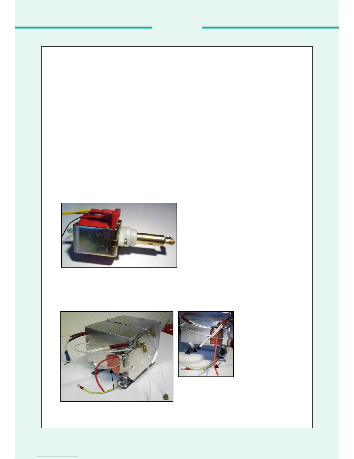
4.2.1 Pump EX5 230V/50Hz
Optical test
Test:
Check if all tubes are connected properly, no fluid is escaped (see 3.3 Fluid circuit).
Solution:
If there are tubes disconnected reconnect them. Is fluid escaped somewhere, have a closer look to the
tubes and fittings maybe there is one leaking. Change the leaking one. Maybe the heat exchanger is
clogged, see test plan for the HE 2400 Heat Exchanger. If there is no fluid escaped or tube
disconnected go on testing.
Function test
Check each pump separately.
Test:
Check if the pump starts working after entering P99, is it ratteling with a 50Hz rhythm? That’s ok. Is it
priming the fluid? Disconnect the pressure pipe (part number 59020) from the HE and check if there is
fluid coming out of it.
Solution:
If there is no sound or no fluid coming out of the disconnected tube, supply the pump directly with 230
VAC. If it’s not working, it is dead. If it’s working, it’s necessary to check the power supply from the
PCB. If the pump is working properly test the HE 2400 Heat Exchanger.
Power supply test
Test:
Check if there is power at pin X1:1/2 resp. at the power connection at the pump (see picture 2.1)
between the yellow and the black cable. At P99 you can measure about 170VAC.
Solution:
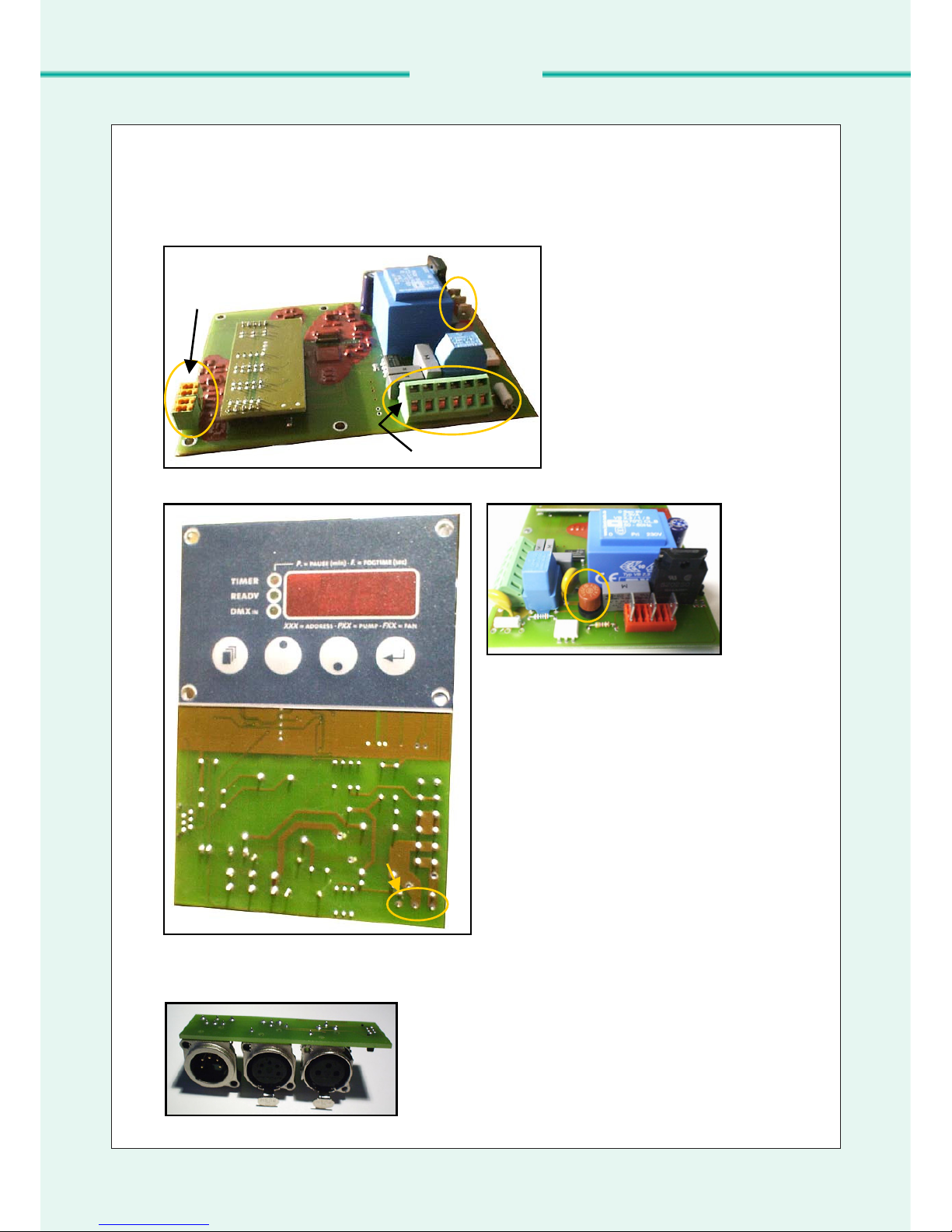
If there is no power check the PCB ENTERPRISE TC4 for function. If there is power and the pump
does work test the HE 2400 Heat Exchanger.
4.2.2 HE 2400 Heat Exchanger
Faults shown in display
Test:
Check the display for faults (E1-E4)
Solution:
Errors displayed:
E-1: Thermocouple A broken or not connected
E-2: Thermocouple B broken or not connected
E-3: Both thermocouples broken or not connected
E-4: Board to hot
For the errors E-1 to E-3 reconnect the thermocouples or change the heat exchanger. For E-4 switch
ENTERPRISE TC4 off and wait till the unit is cooled down.
Function test
Test:
Check if the heat exchanger is heating up (don’t touch it directly, it’s getting really hot, just nearby). If
the pumps are both working properly check if there is less or no fog.
Solution:
If the HE remains cold, measure the resistance of the heater: ENTERPRISE TC4 ca. 20Ω. If the
resistance is much higher, the device needs to be changed.
10 ENTERPRISE TC4 – SERVICE MANUAL
SMOKE FACTORY
FOG & HAZE GENERATORS

If it is possible to see whether there is fog only coming out of one nozzle one vaporizer coil seams to
be clogged. The Heat Exchanger needs to be changed. If there is less fog coming out of one nozzle
then out of the other one coil is partial clogged. The device needs to be changed too.
Power supply test
Test:
Check if there is power 230VAC at pin X1:3/6 resp. at the power connection at the heater (see picture
2.2b) between the red and the yellow/white cable, when the machine is heating up.
Solution:
If there is no power, check the PCB ENTERPRISE TC4 for function. If there is power, the pump does
work properly and there is still no fog the HE 2400 Heat Exchanger must be broken. Change the
device.
4.2.3 PCB ENTERPRISE TC4
The PCB ENTERPRISE TC4 is a processor driven board to control all functions of a DMX-fog-
machine. If there are some malfunctions, it is not possible to repair the board due to its complexity. All
values are pradjusted and stored in the internal memory, so that there is no way to calibrate or change
values. If all mechanical components like pump and heater are checked and the machine is still not
working, change the board.
Optical test
Test:
Check if the PCB is wet, fluid residue ?
Check if something is burned at the boards.
Solution:
If it is wet: clean it (see 4.3).
If something is burned at the board it needs to be changed.
Power supply test
Test:
Check if there is power at the pins X1:4/5 (mains power cord) and for example going out at the pins
X1:1/2 (pump if pumping) or X1:3/6 (heater if heating). Check the proper connection of all wires.
Solution:
If there is not power at the pins X1:4/5 – change the power cord. If the display is fine but there is no
voltage at the pump or heater connectors – change the PCB.
4.2.4 Miscellaneous
Fan connector
If a connected fan does not run, make sure that all wires are connected properly (maybe a continuity
test will help), the fuse and the fuse holder is fine and the fan is a 230VAC type with max. 700Watt.
PCB remote (DMX and analogue)
If the controlling via remote control is not as expected it is maybe the PCB remote board. Try to control
the fog via display. If now the fog is as expected change the PCB remote board.
No additional/ external power supply
After separating a unit for testing, connect this componenet to the origin connection and start the unit,
if no additional power supply is available.
Connections
After opening the case check if all cables and tubes are connected properly.
The Fog
The fog should always smell neutral (not pungent) and should never be wet. If the fog smells
somehow or is displeased, something is wrong. Check the unit and the fog fluid.
Wrong fluid
Using not the original fluid can case clogging of the heater. It is necessary to use only original fluid
available at Smoke Factory (www.smoke-factory.com).
ENTERPRISE TC4 – SERVICE MANUAL 11
SMOKE FACTORY
FOG & HAZE GENERATORS

4.3 How to clean a board accurately
Clean a PCB as follows:
After blown off the fluid residue with a air gun the board will be brushed with alcohol (for example) and
blown off with the air gun again. Do this two or three times to make sure all the residues are gone.
5 Replacement/Mounting/Demounting
Disconnect the ENTERPRISE TC4 unit from main supply (pull the plug out the socket). Screw off
the two screws of the handle on the top. Go on screwing off the six screws at the bottom of the unit.
Finally screw of the two screws of the fluid tank bracket for easier handling (see picture 4a). It’s not
necessary to screw off the feet of the ENTERPRISE TC4.
Picture 4a: Bottom of the ENTERPRISE TC4 unit
Take off the lid and disconnect the yellow/green cable (spanner size 7mm). Locate the PCB
ENTERPRISE TC4 board.
Picture 4b: Open ENTERPRISE TC4 unit
12 ENTERPRISE TC4 – SERVICE MANUAL
SMOKE FACTORY
FOG & HAZE GENERATORS

5.1 Pump EX5 230V/50Hz
Disconnect all connected tubes from the pump and cables from the terminal block (X1:1/2). Cut the
cable tie tying the pump. It is possible to take the broken pump out of the unit without drilling of the
rivets fixing the black rubbers to the housing. Put a new one in and tie the pump with a cable tie. (see
picture 5.1a). Reconnect all tubes and cables as described in 3.2 wire plan and 3.3 fluid circuit.
Picture 5.1a: Tied pump
5.2 HE 2400 Heat Exchanger
Disconnect the power cables from the terminal block (X1:3/6), the thermocouple wires and the tubes.
Drill (drill 5,1mm) the four rivets (see picture 5.2a) fixing the heat exchanger to the housing. Change
the device and fix it with steel/steel rivets 5x8mm. Reconnect all cables (take care of the polarity of the
thermocouple wires)and tubes as described in 3.2 wire plan and 3.3 fluid circuit.
Picture 5.2a: Rivets for heat exchanger
Black
rubber
Cable tie
ENTERPRISE TC4 – SERVICE MANUAL 13
SMOKE FACTORY
FOG & HAZE GENERATORS

5.3 Circuit boards
5.3.1 PCB ENTERPRISE TC4
Place the unit on one side. Disconnect all cables at the terminal block, the flat cable connector, the
thermocouple and the power cable for the fan; see pictures below (5c-f).
To disconnect the cables press a screwdriver in
the hole above the cable. While pushing it down
it is possible to pull out the cable.
Picture 5c: Terminal block
To disconnect the thermocouple press down the orange piece of
the terminal block and pull out the wires, careful the wires are
sharp-edged.
Picture 5d: Thermocouple terminal block
Disconnect the power cables for the fan. It is just necessary to
pull out the red crimps, see picture 5e.
Picture 5e: Power connection of the fan
Hole for
screwdriver
Press
down
Power connection
of the external fan
14 ENTERPRISE TC4 – SERVICE MANUAL
SMOKE FACTORY
FOG & HAZE GENERATORS

Place the unit on the other side. Finally disconnect the flat
cable 6-pin connector, see picture 5f.
Picture 5f: Flat cable 6-pin connector
Next drill off the rivet (see picture 5g) with a drill size 4mm
carefully. Now screw of the four nuts fixing the board at the
case with a spanner 5,5mm. It should be possible to take out
the board now.
Picture 5g: Rivet to fix the triac
Before fixing the new board it’s necessary to fix the triac with a screw (size M4) to the case, don’t
forget the insulation plate. To fix the triac is very important for the heat dissipation. If the triac is
fixed to the case stick the new board in and stick the feet of the triac into the pads on the new board
(position see old board or picture 2.1b). For this it might be necessary to curve the legs.. Now tighten
the four nuts. Solder the triac. The board has to be sealed to the housing with a flowable fluid silicone
rubber compound from RS Nr.: 692542 or a similar substance. Connect all cables as it is described in
the wire plan. Make sure that the green cable of the thermocouple is on the left side (closer to a
screw) and the white cable on the right side (longer distance to a screw) of the green/orange terminal
block. Plug in the power supply cables for the fan and connect the flat cable 6-pin connector.
5.3.2 PCB Remote (DMX and analogue)
Disconnect the flat cable from the board (see picture 5f). Drill the rivets. Take the board out and put a
new one in. Tied it via screws to the lid again. Reconnect the flat cable.
Rivet
Flat cable
Disconnect
on this side
ENTERPRISE TC4 – SERVICE MANUAL 15
SMOKE FACTORY
FOG & HAZE GENERATORS

Smoke Factory GmbH
Walsroder Str. 159 A, 30853 Langenhagen/Hannover, Germany
Tel.: +49-(0) 511-51 51 02-0, Fax: +49-(0) 511-51 51 02-22
Mail: info@smoke-factory.de, www.smoke-factory.de
5.4 Testing after exchange
Before closing the ENTERPRISE TC4 unit do the function test. After closing the lid do the final test.
5.4.1 Function test
1. Test the ENTERPRISE TC4 unit via display (up/down of Pxx) by pressing the button
2. Test the ENTERPRISE TC4 unit via analogue exit at the front side (e.g. the control board of
the lighting)
3. Test the ENTERPRISE TC4 unit via DMX control on the top
5.4.2 Final test
For this testing a special gage (e.g. Neuberger,TG 0701) for testing hardware is necessary. The
following tests are necessary:
1. Earth resistance test:
Checks if the metal housing is good connected to earth. Kind of continuity test. The resistance
(low) resp. the current flow between the earth pin of the power socket and the housing will be
measured.
2. Insulation resistance test:
The resistance between earth and one phase will measured (very high resistance)
3. Leakage current test:
If the ENTERPRISE TC4 unit is running the leakage current needs to be in the admissible
range (e.g. this part of the display in the gage is green and the not allowed range is red).
SMOKE FACTORY
FOG & HAZE GENERATORS
Table of contents
Other Smoke Factory Fog Machine manuals

Smoke Factory
Smoke Factory Data ll User manual

Smoke Factory
Smoke Factory Spaceball II User manual

Smoke Factory
Smoke Factory Carpet Crawler User manual

Smoke Factory
Smoke Factory Captain D. User manual

Smoke Factory
Smoke Factory Tour Hazer II User manual

Smoke Factory
Smoke Factory Spock User manual

Smoke Factory
Smoke Factory Spaceball II User manual
Popular Fog Machine manuals by other brands

MAGMATIC
MAGMATIC MAGMA PRIME user manual

EuroLite
EuroLite N-110 Smoke-machine user manual

Varytec
Varytec Stage Master S-1200 user manual

involight
involight FM400-E Important safety instructions

Esu
Esu 54678 Installation and operating instructions

Home Accents Holiday
Home Accents Holiday FM1000-ASH user manual