SMS ISKRA ME371 Parts list manual

Energy Measurement and Management
ME371,
MT371
Single- and Three-Phase
Electronic Meters with Built-in
DLC Communication Channel
ME372,
MT375
Single- and Three-phase
Electronic Meters with Built-in
GSM/GPRS Modem or RS485
Communication Interface
Technical
Description
EAD 020.611.325
Version 2.00, 29.05.2008

Energy Measurement and Management
Content:
Revision history....................................................3
Mx37y – Single- and Three-phase electronic
meters.....................................................4
1. Energy measurement and registration...........6
1.1. Multi-tariff registration...................................6
1.2. Power measurement....................................6
1.3. Load-profile ..................................................6
1.4. Supplied energy or power limitation.............7
1.5. Code red.......................................................7
1.6. Prepaid functionality.....................................7
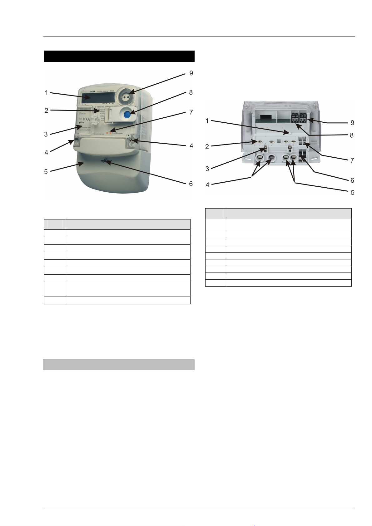
2. Meter appearance (ME37y)...............................9
2.1. Meter case (ME37y).....................................9
2.2. Overall and fixing dimensions (ME37y)......10
2.3. Meter configuration (ME37y)......................10
2.4. Metering system (ME37y) ..........................10
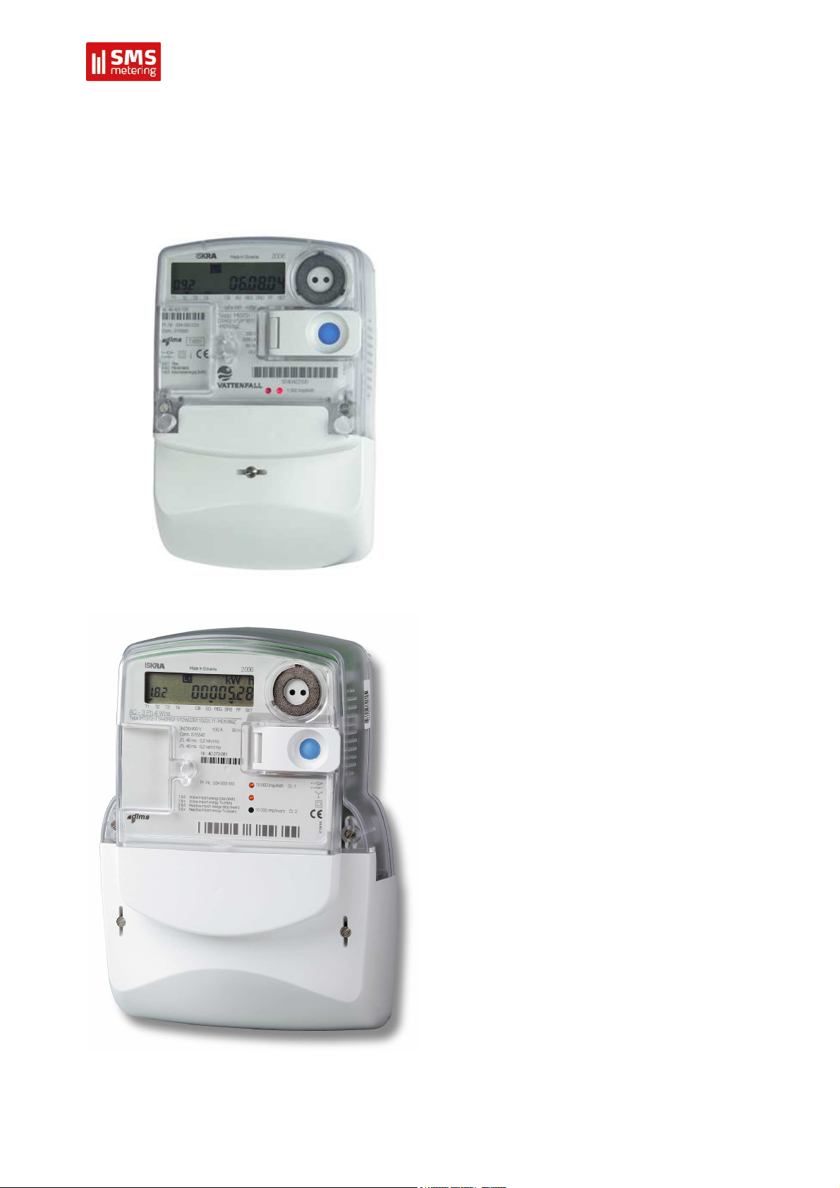
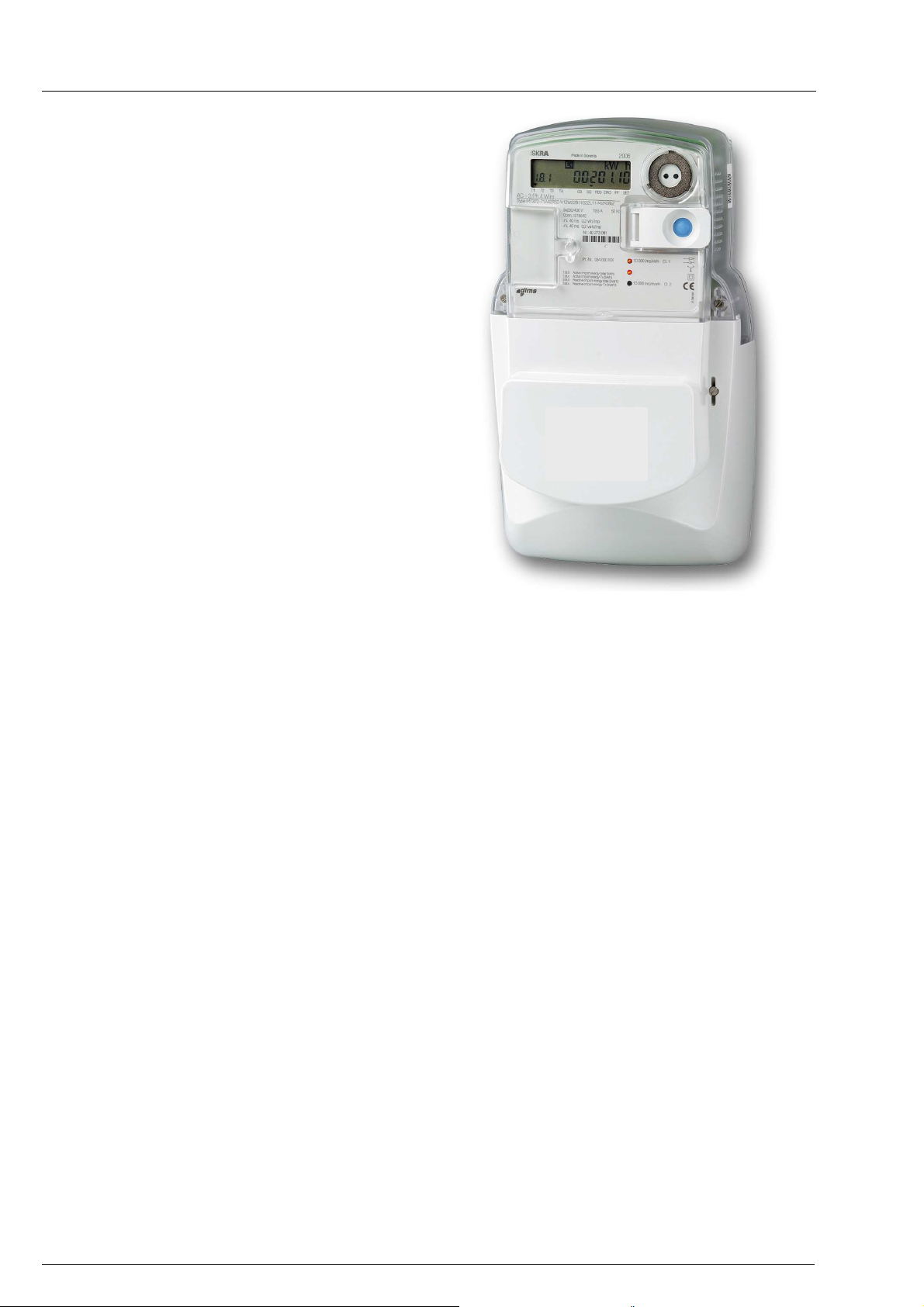
3. Meter appearance (MT37y).............................11
3.1. MT371….....................................................11
3.2. MT372….....................................................11
3.3. Meter case (MT37y)...................................11
3.4. Overall and fixing dimensions (MT371)......14
3.5. Overall and fixing dimensions (MT372)......15
3.6. Meter configuration (MT37y)......................15
3.7. Metering system (MT37y)...........................16
4. Meter configuration ........................................16
4.1. Power supply unit.......................................16
4.2. Microcontroller with FRAM.........................16
4.2.1. Load-profile recorder ...........................16
4.2.2. Log-book..............................................17
4.2.3. Keeping of billing results......................17
4.3. Real-time clock (RTC)................................17
4.3.1. Time-of-use registration.......................17
4.3.2. Maximum demand...............................17
4.4. Liquid Crystal Display – LCD .....................18
4.4.1. Data display.........................................18
4.4.2. Signal flags..........................................18
4.5. LED.............................................................19
4.6. Push-buttons ..............................................19
4.6.1. RESET and SCROLL push-button......19
4.6.2. Manual meter billing reset ...................22
4.7. Communication channels...........................22
4.7.1. Optical port – IR communication
interface................................................23
4.7.2. DLC modem (Mx371) ..........................23
4.7.3. Integrated GSM/GPRS communication
interface with antenna (option) (Mx372) 23
4.7.4. RS485 communication interface (option)
(Mx372).................................................23
4.7.5. M-Bus communication interface (option)
.............................................................. 23
4.7.6. Readout via built-in communication
interfaces.............................................. 23
4.8. AMR readout.............................................. 24
4.9. Inputs and outputs (ME37y)....................... 25
4.9.1. Alarm inputs ........................................ 25
4.9.2. Load control output.............................. 25
4.10. Inputs and outputs (MT37y)..................... 25
4.10.1. Inputs................................................. 25
4.10.2. Outputs.............................................. 25
5. Additional meter functions............................ 26
5.1. On request reading of E-meter ..................26
5.2. Billing registers reading of E-meter............ 26
5.3. Scheduled reading of E-meter................... 26
5.4. Historic reading of E-meter........................ 26
5.5. On request reading of G-meter.................. 26
5.6. Billing registers reading of G-meter ........... 26
5.7. Scheduled reading of G-meter................... 26
5.8. Historic reading of G-meter........................ 27
5.9. Device status ............................................. 27
5.10. Tariff structure configuration of E-meter.. 27
5.11. Remote customer connection/disconnection
................................................................. 27
5.12. Load-profile reading of E-meter............... 27
5.13. Load-profile reading of G-meter............... 27
5.14. Load-profile configuration of E-meter ...... 27
5.15. Load-profile configuration of G-meter...... 28
5.16. Power quality ........................................... 28
5.17. Power failure registration......................... 28
5.18. Alarms...................................................... 28
5.19. Commission E-meter ............................... 29
5.20. Security.................................................... 29
6. Data protection ............................................... 29
7. Meter connection procedure......................... 29
7.1. Connection procedure of GSM/GPRS
communication interface.......................... 30
8. Accessory for meters managing................... 30
9. Meter maintaining........................................... 30
10. Anti-fraud protection.................................... 31
10.1. Position of the seals................................. 31
10.2. Wire seals ................................................ 31
11. Front plate..................................................... 32
12. Meter connection.......................................... 32
12.1. Meter connection of ME37y meters......... 32
12.2. Meter connection of MT37y meters......... 33
13. Technical data............................................... 34
14. Type designation.......................................... 37

Mx37y_Technical_Description_ENG_v2.00.doc 3
Mx37y
─Single- and three-phase electronic meters with built-in DLC
modem, GSM/GPRS modem or RS485 comm. interface
Revision history
Version Date Comment
1.00 12.10.2007 Initial version
2.00 29.05.2008 Double-cage clamp, Capacity of the load-profile recorder 1 and 2, Billing profiles
1 and 2, Alarm inputs, List of error statuses, List of events in event log, Anti-
fraud protection, Front plate, Type designation, standards EN 50470–1 and EN
50470–3

Mx37y_Technical_Description_ENG_v2.00.doc
4
Mx37y
─Single- and three-phase electronic meters with built-in DLC
modem, GSM/GPRSmodem orRS485comm. interface
Mx37y – Single- and Three-phase
electronic meters
The Mx37y single- and three-phase electronic meters
are designed for measuring and registration of active,
reactive and apparent energy in single phase or in
three-phase four- or three-wire network for direct and
indirect connection. Measuring and technical
characteristics of meters comply with the IEC 62052-
11 and IEC 62053-21 international standards for
electronic active energy meters, class 1 or 2 (MID,
class B or A) , and reactive energy meters, classes 2
or 3 in compliance with IEC 62053-23 as well as a
standard for time switches IEC 62052-21.
Measuring and technical characteristics of the meters
also comply with the MID standards: EN 50470–1
(Electricity metering equipment - General
requirements, tests and test conditions - Metering
equipment: class indexes A, B and C) and EN
50470–3 (Electricity metering equipment - Particular
requirements - Static meters for active energy: class
indexes A, B and C).
Meters are designed and manufactured in
compliance with the standards and ISO 9001 as well
as more severe Iskraemeco standards.
The Mx37y meters are the third generation of
Iskraemeco electronic single- and three-phase
meters for a deregulated market of electric power,
with the following common functional properties:
•Time-of-use measurement of active energy
and maximum demand (in up to 4 tariffs)
•Load-profile registration
•LCD in compliance with the VDEW
specification
•Internal real-time clock
•Two push-buttons: Reset and Scroll
•Optical port in compliance with the IEC
62056-21 standard for local meter
programming and data downloading
•Built-in interface or a modem for remote
meter programming and data downloading
•Impulse output
•M-Bus – multi-utility (option)
•Plug-in switching device (option)
•Prepayment functionality (option)
•Limitation of supplied energy or power
(option)
•Code red (option)
•Remote connection and disconnection of
energy supply to individual customers
(option)
The first generation of Iskraemeco electronic meters
for a deregulated market of electric power, i.e. the
Mx42y meters were provided with RS232 or RS485
interface for remote two-way communication, and
utilized IEC 62056-21, mode C communication
protocol.
The second generation of Iskraemeco electronic
meters for a deregulated market of electric power, i.e.
the Mx351 were provided with an integrated DLC
modem for two-way communication via low voltage
distributions network - or upon request - RS485
interface instead, for remote two-way communication.
It utilized the DLMS communication protocol in
compliance with the IEC 62056-51 standard as well
as IEC 62056-21, mode C protocol. These meters
had the following additional functional properties:
•Indication of incorrect connection,
•Bistable relay for demand control
•Two S0 impulse inputs (option).
The third generation of Iskraemeco electronic single-
and three-phase meters for a deregulated market of
electric power consists of Mx37y meter types: with
built-in DLC communication channel (Mx371) or
GSM/GPRS modem – or upon request – with RS485
interface instead (Mx372), for remote two-way
communication.
The meter utilizes the DLMS communication protocol
in compliance with the IEC 62056-46 standard as well
as IEC 62056-21, mode C protocol. Further to the
Mx37y meters functionality they also include:
•Detectors of the meter and the terminal cover
opening
•Switching device for remote disconnection /
reconnection at the customer premises
(option)
•M-Bus for reading other meters (heat, gas,
water)

Mx37y_Technical_Description_ENG_v2.00.doc 5
Mx37y
─Single- and three-phase electronic meters with built-in DLC
modem, GSM/GPRS modem or RS485 comm. interface
Fig. 1: MT371 meter with ZO3 plug-in switching device
Mx37y meters properties:
•Active energy and demand meter
Accuracy class 1 or 2
•Reactive energy meter
Accuracy class 2 or 3
•Apparent energy meter
•Modes of energy measurement and
registration (single-phase meters)
For one-way energy flow direction
For two-way energy flow direction
For two-way energy flow direction but
registered in one (absolute) register
•Modes of energy measurement and
registration (three-phase meters)
For one-way energy flow direction, three-phase
energy is algebraic sum of energies registered
in each of the phases – meters are equipped
with an electronic reverse running stop
For two-way energy flow direction, three-
phase energy is algebraic sum of energies
registered in each of the phases
For one-way energy flow direction, three-
phase energy is sum of absolute values of
energies registered in each of the phases
•Meter connection to network
The three-phase meter can function as a single-
phase or a two-phase meter
•Meter quality:
Due to high accuracy and long-term stability
of metering elements no meter re-calibration
over its life is required
High meter reliability
High immunity to EMC
•Additional meter functions:
Current measurement in a neutral conductor
via the fourth measuring system:
Detection of missing/broken neutral conductor
Detection of phase and voltage unbalance
Measurement and registration of under- and
over-voltage
Generation of alarms and their transmitting
via the DLC modem and low voltage network
(“alarm pull” at Mx371 – the concentrator
reads Alarm ON status and Alarm OFF status
register from the meter) or via GSM/GPRS
modem or the RS485 communication
interface (“alarm push” at Mx372 – GSM
modem constantly reads Alarm ON status
and Alarm OFF status register from the meter
and, if any alarm is active and enabled, it
tries to notify the centre about the alarm)
•Time-of-use registration (up to 4 tariffs):
Tariffs change-over; internal real-time clock
•Load-profile recorder:
Two load-profile recorders (i.e. daily and
hourly values)
•Communication channels:
Infrared optical port in compliance with the
IEC 62056-21 for local meter programming
and data downloading
Built-in DLC modem (Mx371)
GSM/GPRS modem (Mx372) or
Built-in RS485 comm. interface (Mx372)
Built-in M-Bus comm. interface (option)
•LCD:
In compliance with the VDEW specification
•Data display modes:
Automatic cyclic data display with display
time of 10 sec.
Manual data display mode (by pressing the
Scroll push-button)
•Indicators:
on LCD:
- Presence of phase voltages L1, L2, L3
- Phase currents flow direction
- Actual tariff indication
- Status of switching device
- Meter status and alarms
- 3-state GSM signal level indicator (Mx372)
LED1: Imp / kWh
LED2: Imp / kVArh
•Communication protocols:
Optical port: IEC 62056 – 21, mode C or
DLMS (in compliance with IEC 62056 – 46)

Mx37y_Technical_Description_ENG_v2.00.doc
6
Mx37y
─Single- and three-phase electronic meters with built-in DLC
modem, GSM/GPRSmodem orRS485comm. interface
DLC modem (Mx371): DLMS by IEC 62056–46
GSM/GPRS modem (Mx372); IEC 62056 – 46
RS485 Interface (Mx372); IEC 62056 – 46
Identification system; IEC 62056 – 61
COSEM organization of data: IEC 62056-53
M-Bus: EN 13757-2 and EN 13757-3
•OBIS data identification code: IEC 62056–61
•Auxiliary inputs / outputs:
Output for load control with a 6 A relay
Output for load control with an Optomos relay
Alarm input (low voltage)
M-Bus interface to which up to 4 gas, heat or
water meters can be connected (also a switching
device ZO340-D1)
Two impulse outputs or an output for control of
a switching device (ZO320-D1)
•Automatic configuration of an AMR system:
Meters are registered automatically into an
AMR system (Intelligent Network Management)
•Automatic meter setting into the repeater
mode (DLC repeater) :
Each meter can automatically enter into the
repeater mode and transmit data in both
directions, even with meters with which it can
not communicate directly.
Data transmission of max. 7 remote meters
which temporarily operate in the repeater
mode increases efficiency of communication
and distance between the meters and a data
concentrator.
•Call-back (Mx372):
The meter can perform a call and send a
message to the centre:
- After installation
- If a pre-defined alarm condition exists (e.g.
after Power Down/Up event)
- If a signal appears on the alarm input
•Programming:
Programming of the meter as well as Firmware
upgrade can be done locally (via an optical port)
or remotely (via GSM modem – Mx372) in
compliance with the predefined security levels.
•Detection of meter and terminal cover
opening
•Simple and fast meter installation
•Current terminals:
Make good contact with current conductors
irrespective of their design and material
Do not damage conductors
•Voltage terminals:
Internal and/or external connection
A sliding bridge (for simple separation of a
voltage part from a current part)
•Compact plastic meter case:
Made of high quality self-distinguishing UV
stabilized material that can be recycled
IP54 protection against dust and water
penetration (by IEC 60529)
1. Energy measurement and registration
The meter measures and records electric energy:
•In a single-phase two-wire network (also
MT37y)
•Three-phase three-wire network (MT37y)
•Three-phase four-wire network: (MT37y)
total (∑Li)
only positive active energy
positive and negative active energy (A+, A-)
separately
absolute active energy A
only positive reactive energy
positive and negative reactive energy (R+,R-)
separately
apparent energy
Meters are provided with two LEDs on the front plate.
They are intended for checking the meter accuracy.
Impulse constant depends on the meter version
(direct or current transformer meter).
1.1. Multi-tariff registration
The meter enables registration of energy and power.
Up to four tariffs (8 tariffs is an option) for power and
energy can be registered. Tariff changeover is
defined with hour and minute. Minimal resolution
between changeovers is one minute.
Different combinations of the tariff program are
avaliable:
•Up to 4 tariff rates (8 rates as an option)
•Up to 4 seasons
•Up to 4 day types (8 as an option)
•Up to 8 individual changeovers inside individual
daily program
•Up to 32 programmable holidays
•Support to lunar holidays in compliance with
the Gregorian calendar.
1.2. Power measurement
Power is measured inside a measuring period. The
measuring period is a meter parameter and can be
set. Values that can be set are 15, 30 and 60
minutes. After termination of the measuring period,
the measured meter value is transferred from current
measuring period registers to registers for previous
measuring period that can be later used for the
formation of billing profile values.
1.3. Load-profile
Two load-profile recorders can be provided with up to
16 channels (values) each. In the first load-profile

Mx37y_Technical_Description_ENG_v2.00.doc 7
Mx37y
─Single- and three-phase electronic meters with built-in DLC
modem, GSM/GPRS modem or RS485 comm. interface
(time stamp, status, register-value) approx. 33,000
records (60 minutes, ~ 1400 days) and in the second
-one approx. 190 (1 day, ~ 190 days) records can be
recorded. The saving period (a recording period) can
be set. Available values are 15, 30 and 60 minutes or
a daily value.
Data in a load-profile recorder are accompanied with
a time stamp and with the meter status in the last
saving period as well as with a check sum. The time
stamp indicates the end of a registration period.
Memory capacity of the load-profile recorder for 15-
minute registration period is around 190 days
(extended load-profile capacity).
1.4. Supplied energy or power limitation
The limitation or disconnection functionality can be
activated in the meter itself or by remote action.
The meter disconnects the network (via a switching
device) if a maximum energy limit was exceeded
during a predefined period of time. The energy level
and the allowed exceeding period are set in the
meter.
The meter disconnects the network if a maximum
power limit was exceeded during a predefined period
of time. The power level and the allowed exceeding
period are set in the meter.
The customer can (after correcting the exceeding
level) reconnect network manually (by pressing the
blue button on the meter for 2-5 sec.).
1.5. Code red
“Code Red” is the situation of possible power
shortage e.g. due to limitation cooling capacity of the
power generation during hot summers. For such
situations, in accordance with certain extent, the
function can be activated. A “code red” situation is
usually preceded by a “code orange”. A “code red”
situation typically lasts for a period of few days.
COSEM Objects
Code Red Group ID,
Code Red Start Date,
Code Red Duration,
Code Red Power Limit,
Code Red Active,
Code Red Remaining Duration,
Code Red Meter Group ID.
During “code red” situations the necessary total
power amount is limited by setting the maximum
consumption threshold of a large number of individual
customers (group) to a lower level. This level may be
different for individual meters according to the
consumer’s contract. Handling “code red” involves a
broadcast to all meters and only pre-programmed
meters (members of that particular group) shall
respond to this action.
Depending on the customer contract the reduction
can vary from 0% to 100%. This Information is a part
of the configuration ID. The maximum contractual
reduction levels are presented in the Configuration
Identifier as Code Red ID.
A broadcast shall indicate the group ID, the date and
time of which the reduction becomes effective, and
the duration of the reduction.
1.6. Prepaid functionality
Prepaid functionality means that a meter only allows
consumption up to a remotely pre-set amount of
energy or credit paid in advance. At the moment
when no more credit is available, or an amount is
exceeded, the meter disconnects the customer from
the electric network.
A specified prepaid register counts at a rate equal to
the amount of consumed energy. The customer can
revalue the prepayment meter remotely (tokenless).
The prepaid register is tariff based. If the total amount
of prepaid cost for energy is consumed, the meter will
limit the level (as a warning) for a certain amount of
energy before totally disconnecting. If the prepaid
amount limit is reached, the customer will be
informed by an acoustic signal.
E-meter can operate in Credit or Prepayment Mode
depending on the Energy Mode. In Prepayment Mode
Available Credit can be revalued with Transaction.
Prepayment accounting
The implementation of prepayment accounting
functions can be separated into credit and charge
functions. The credit functions include:
•token credit function,
•emergency credit function.
Two types of charge functions are implemented:
•consumption-based tariff charges,
•time-based auxiliary charges.
Token credit:
Token Credit function deals with managing credit
registers according to credit token transfer. When
credit transfer is accepted, the values of “Available
Credit Register” and “Total Purchase Register” are
increased for the amount credit transferred.
Emergency credit:
Emergency credit function is used in situations when
“Available Credit Register Value” approaches or goes
under zero. For this purpose, three parameter objects
are implemented:
- “Emergency Credit Initial Limit” is used once after
meter installation for the purpose of enabling the
customer to make the first buy (or transferring the first
credit from the management centre). It defines the
credit value which is available when emergency credit
is first selected by the customer.

Mx37y_Technical_Description_ENG_v2.00.doc
8
Mx37y
─Single- and three-phase electronic meters with built-in DLC
modem, GSM/GPRSmodem orRS485comm. interface
- “Emergency Credit Limit” defines the credit value
which is available after the value of “Available Credit
Register” reaches zero and the customer selects the
emergency credit.
- “Emergency Credit Threshold” defines the positive
value of “Available Credit Register” at which the
meter begins to notify the customer that the credit will
expire. When the value of “Available Credit Register”
falls below the value of “Emergency Credit
Threshold”, the meter starts notification.
Emergency credit must always be selected by the
customer otherwise the meter disconnects the
customer from the grid when “Available Credit
Register” reaches zero.
Consumption-based tariff charging:
Consumption-based tariff charging is bound to energy
consumption register via “Energy Register
Reference” object which contains the COSEM logical
name of energy consumption register.
In each accounting period the meter calculates the
increment of energy consumption from the previous
accounting period. The increment is then multiplied
by the appropriate tariff charge rate according to
meter tariff definition. The calculated charge advance
based on consumption is finally charged from the
customer’s credit.
Time-based auxiliary charging:
This charging function is used for charges that are
fixed over predefined period of time defined as one
month. The accounting period of time-based auxiliary
charges is one minute. This means that the meter
calculates the minute value of auxiliary charge by
dividing the auxiliary charge for one month with the
number of minutes per month. The minute values are
then charged from the customer’s credit every
minute. When the meter is powered down, the
auxiliary charge is done after power-up, including
charges for the whole period of time when the meter
was powered-off.
Fig. 2: MT372 meter with ZO3 plug-in switching device

Mx37y_Technical_Description_ENG_v2.00.doc 9
Mx37y
─Single- and three-phase electronic meters with built-in DLC
modem, GSM/GPRS modem or RS485 comm. interface
2. Meter appearance (ME37y)
Fig. 3: Meter ME37y constituent parts
ITEM DESCRIPTION
1 Liquid crystal display (LCD)
2 Meter tehnical data
3 Legend for data displayed on LCD
4 A meter cover sealing screw
5 A terminal cover
6 A terminal cover sealing screw
7 Impulse LED
8 Scroll (blue) and Reset (orange) push-
buttons
9 IR optical interface
Two screws for fixing the meter cover (item 4) are
sealed with metrological seals.
The screw for fixing the terminal cover (item 6) and
the Reset push-button lid (item 8) are sealed with
seals of electric utility.
2.1. Meter case (ME37y)
A compact meter case consists of a meter base with
a terminal block and fixing elements for mounting the
meter, a meter cover and a terminal cover. The case
is made of self-distinguishing UV stabilized
polycarbonate which can be recycled. The case
ensures double insulation and IP54 (IEC 60529)
protection level against dust and water penetration.
The top hanger is provided on the back side of the
meter base, under the top edge. On request, an
extended top hanger can be mounted on the meter
base, which ensures the upper fixing hole height of
155 mm above the line connecting the bottom fixing
holes (DIN 43857).
The meter cover is made of transparent polycar-
bonate. A nickel-plated iron ring in the right top corner
is utilized for attaching an optical probe to the optical
port. There is a lid which is fixed to the meter cover
with a hinge. The lid covers the Reset push-button
and can be sealed in the closed position.
The terminal block contains current terminals,
auxiliary terminals and potential links for supplying
potential circuits of the meter.
Fig. 4: A terminal block of ME37y meter
ITEM DESCRIPTION
1 A switch for detection of terminal cover
opening
2 A screw for fitting current cables
3 Additional voltage terminals
4 Current terminals
5 Neutral terminals
6 Load control output
7 M-Bus communication interface
8 Second alarm input
9 First alarm input
Current terminals (item 4) are made of galvanized
iron sheet. They are universal terminals for all shapes
and cross sections of connected conductors up to
35 mm2. The terminals ensure the same contact
quality with conductors irrespective of whether they
are made of copper or aluminum. Only one screw in a
current terminal reduces time needed for the meter
installation in the field. Due to the indirect pressure on
the conductor it is not damaged.
Up to 8 auxiliary terminals can be fitted in the meter.
They can be utilized for M-Bus, bistable 6 A relay for
load control or alarm inputs. Inputs and outputs are
fitted into the meter regarding the customers request
at meter ordering.
Voltage terminals (item 3) are built into the meter
upon request. They are intended for supplying an
add-on unit from the meter terminal block.
Detectors of opening the terminal cover (item 1) and
the meter cover are built into the meter.
The terminal cover can be long or short. The meter
connection diagram is stuck on the internal side of
the terminal cover.

Mx37y_Technical_Description_ENG_v2.00.doc
10
Mx37y
─Single- and three-phase electronic meters with built-in DLC
modem, GSM/GPRSmodem orRS485comm. interface
For single phase meters BS terminal block (Imax =
100 A) is possible too.
2.2. Overall and fixing dimensions
(ME37y)
Fig. 5a: Overall and fixing dimensions of a meter fitted with
a long terminal cover
Fig. 5b: Overall and fixing dimensions of a meter fitted with
a short terminal cover
2.3. Meter configuration (ME37y)
SD
SD
detectioion
SD - Switching device
Fig. 6: ME371 meter block diagram
GSM/GPRS MODEM
or
Rs485 COMMUNICATION INTERFACE
SD - Switching device
Fig. 7: ME372 meter block diagram
2.4. Metering system (ME37y)
Besides precision measurement of active, reactive,
apparent energy and demand in a wide metering and
temperature range, the metering system enables
measurement of phase voltages, currents and supply
quality.
One metering element is built in the meter. The
current sensor is shunt, while voltage sensor is
resistive voltage divider. Signals of currents and
voltages are fed to the A/D converters, and then they
are digitally multiplied so that instantaneous power is
calculated. The instantaneous powers are integrated
and summed in a microcontroller, as well as further
processed.
SD
SD
detection

Mx37y_Technical_Description_ENG_v2.00.doc 11
Mx37y
─Single- and three-phase electronic meters with built-in DLC
modem, GSM/GPRS modem or RS485 comm. interface
3. Meter appearance (MT37y)
3.1. MT371…
Fig. 8: MT371 meter constituent parts
1. Meter base 6. Scroll push-button
2. Meter cover 7. Cover of Reset push-
button
3. Fixing screw of meter
cover 8. LED
4. LCD 9. Terminal cover
5. Optical port 10. Fixing screw of
terminal cover
Two screws for fixing the meter cover (item 3) are
sealed with metrological seals.
Two screws for fixing the terminal cover (item 10) and
the Reset push-button lid are sealed with seals of
electric utility.
3.2. MT372…
Fig. 9: MT372 meter constituent parts
1. LCD 8. A terminal cover
2. Technical data 9. A project number
3. Coupling circuit 10. A meter BAR code
4. A legend of registers
displayed on LCD 11. Impulse LEDs
5. Meter cover sealing
screws 12. Meter technical data
6. A meter serial number 13. SCROLL and RESET
push-buttons
7. Terminal cover sealing
screws
Two screws for fixing the meter cover (item 5) are
sealed with metrological seals.
Two screws for fixing the terminal cover (item 7) and
the Reset push-button lid are sealed with seals of
electric utility.
3.3. Meter case (MT37y)
A compact meter case consists of a meter base with
a terminal block and fixing elements for mounting the
meter, a meter cover and a terminal cover. The case
is made of self-extinguishing UV stabilized
polycarbonate which can be recycled. The case
ensures double insulation and IP54 (IEC 60529)
protection level against dust and water penetration.
The top hanger is provided on the back side of the
meter base, under the top edge. On request, an
extended metal top hanger can be mounted on the
meter base, which ensures the upper fixing hole
height of 230 mm above the line connecting the
bottom fixing holes (DIN 43857).
1
2
3
4
5
6
7
8
2
1
9
7
3
4
5
6
8
10
10

Mx37y_Technical_Description_ENG_v2.00.doc
12
Mx37y
─Single- and three-phase electronic meters with built-in DLC
modem, GSM/GPRSmodem orRS485comm. interface
The meter cover is made of transparent
polycarbonate. A nickel-plated iron ring in the right
top corner is utilized for attaching an optical probe to
the optical port. There is a lid which is fixed to the
meter cover with a hinge. The lid covers the Reset
push-button and can be sealed in the closed position.
A terminal block complies with the DIN 43857
standard. It is made of high quality polycarbonate
assuring resistance to high temperatures, voltage-
breakdown and mechanical strength.
Fig. 10: A terminal block of MT371 meter – bottom view
1. Current terminals 3. Voltage terminals for an
add-on unit
2. Auxiliary terminals 4. Detector of opening a
terminal cover
Fig. 11: A terminal block of MT372 meter – bottom view
1. Current terminals 4. Detector of opening a
terminal cover
2. Auxiliary terminals
3. Additional voltage
terminals
5. Auxiliary terminals –
inputs, outputs, SIM
card bed, alarm
inputs, etc.
Current terminals (item 1) are made of zinc-plated
iron and have only one screw. A universal clamping
terminal assures the same quality of the contact
irrespective of the shape of the connection conductor
(a compact wire, a stranded wire, greater or smaller
cross-sections). It also assures faster meter
assembly. Available current terminals are:
•Current terminal according to DIN standard for
currents up to 85 A with 8.5 mm hole diameter
•Current terminal for currents up to 120 A with
9.5 mm hole diameter
•Current terminal for CT meters for currents up
to 6 A with 5.5 mm hole diameter
The meter can be equipped with max. four additional
voltage terminals (item 3): 2 (L1), 5 (L2), 8 (L3), 11
(N). They enable simple connection of additional
external devices.
Up to 6 auxiliary terminals (item 2) can be fitted in the
right side of the current terminals. They can be
utilized for M-Bus and optomos relay impulse output
or optomos relay control output. Instead of the
optomos relay a 6 A bistable relay for load control
can be built into the meter. All of them are fitted into
the meter regarding the customer request at meter
ordering.
Versions:
- two pulse outputs (A+, R+) and relay (6 A) +
optomos (100 mA)
- M-Bus and relay (6 A) + optomos (100 mA)
Detectors (switches) of the terminal cover (item 4)
and the meter cover opening (on the PCB next to the
optical port) are built into the meter.
A sliding voltage bridge is intended for fast and
simple separation of meter current and voltage circuit
used for calibration or accuracy testing. A special
slider is built in each phase of the connection
terminal. It can be shifted up and down with a
screwdriver.
Sliding voltage bridge Auxiliary terminals
Fig. 12a: A terminal block – sliding voltage bridge and
auxiliary terminals
When a voltage bridge is in “0” position, it means that
the voltage part is separated from the current part.
During the meter testing and calibration the sliding
voltage bridges should be in position “0”.
Position 0
Position 1
1
3
4
2
5

Mx37y_Technical_Description_ENG_v2.00.doc 13
Mx37y
─Single- and three-phase electronic meters with built-in DLC
modem, GSM/GPRS modem or RS485 comm. interface
When a voltage bridge is in position “1”, the voltage
part is not separated from the current part. During the
normal meter operation the potential links should be
closed (position “1”). Upon request, the potential links
can be built under the meter cover.
1 Double cage clamp
2 Auxiliary terminals
Fig. 12b: A terminal block with auxiliary terminals
MT37y : 3x230/400 V, 10(120) A
1 Auxiliary terminals
2 Terminal cover sealing screw
Fig. 12c: A terminal block with auxiliary terminals
MT37y CT : 3x230/400 V, 5(6) A
The terminal cover can be long or short. The meter
connection diagram is stuck on the internal side of
the terminal cover.
Fig. 13: Details of a terminal block for GSM/GPRS meter
1. Coupling circuit for
external antenna 6. Additional voltage
terminals
2. SIM card bed 7. Outputs for load control
3. Current terminals 8. M-Bus
4. A sliding voltage bridge 9. Output for switching
device control
5. A switch for detection of
terminal cover opening 10. Alarm input (low
voltage)
Fig. 14: Details of a terminal block for RS485 meter
1. RS485 comm.
interface 6. Outputs for load control
2. Current terminals 7. M-Bus
3. Sliding voltage bridge 8. Output for switching
device control
4. A switch for detection
of terminal cover
opening 9. Alarm input (low voltage)
5. Additional voltage
terminals
2
1

Mx37y_Technical_Description_ENG_v2.00.doc
14
Mx37y
─Single- and three-phase electronic meters with built-in DLC
modem, GSM/GPRSmodem orRS485comm. interface
3.4. Overall and fixing dimensions
(MT371)
Mounting and fixing meter dimensions comply with
the DIN 43857 standard.
Fig. 15a: Overall and fixing dimensions of an MT371
meter fitted with a long terminal cover
Fig. 15b: Overall and fixing dimensions of an MT371
meter fitted with a short terminal cover
Fig. 16: Overall and fixing dimensions of an MT371 meter
fitted with a switching device and a long terminal cover

Mx37y_Technical_Description_ENG_v2.00.doc 15
Mx37y
─Single- and three-phase electronic meters with built-in DLC
modem, GSM/GPRS modem or RS485 comm. interface
3.5. Overall and fixing dimensions
(MT372)
Mounting and fixing meter dimensions comply with
the DIN 43857 standard.
Fig. 17a: Overall and fixing dimensions of an MT372 meter
fitted with a long terminal cover
Fig. 17b: Overall and fixing dimensions of an MT372 meter
fitted with a short terminal cover
Fig. 18: Overall and fixing dimensions of an MT372 meter
fitted with a switching device and a long terminal cover
3.6. Meter configuration (MT37y)
OPTION
M-Bus
Fig. 19: MT371 meter block diagram
Fig. 20: MT372 meter block diagram
1.2.3. Three metering
elements (on request four)
10. GSM/GPRS with a bed
for a SIM card or RS485
communication interface
4. A meter power supply unit 11. Inputs; alarm
5. A microcontroller with
17. FRAM memory
12.13. Outputs: relay,
switching device control or
M-Bus communication
interface
6. Liquid Crystal Display–LCD 14. Tariff inputs
7. Impulse diodes (LED) 15. Control circuits
8. Push buttons (Reset and
Scroll) 16. Real time clock - RTC
9. IR optical interface

Mx37y_Technical_Description_ENG_v2.00.doc
16
Mx37y
─Single- and three-phase electronic meters with built-in DLC
modem, GSM/GPRSmodem orRS485comm. interface
3.7. Metering system (MT37y)
Besides precision measurement of active energy and
demand in a wide metering and temperature range,
the metering system enables measurement of phase
voltages and currents.
Three (on request four) metering elements are built in
the meter. The current sensor is the Rogowski coil (a
current transformer with an air core), while a voltage
sensor is a resistive voltage divider. Signals of
currents and voltages are fed to the A/D converters,
and then they are digitally multiplied so that
instantaneous power is calculated. The instantaneous
powers are integrated and summed in a
microcontroller, as well as further processed.
Fig. 21: Metering element
Explosion view of the Rogowski coil is shown in the
figure bellow.
I
Fig. 22: Explosion view of the Rogowski coil
1. Rogowski coil frame 3. Two Rogowski coils
(secondary winding)
2. Meter current loop
(primary winding) 4. Printed circuit board
The metering elements ensure excellent metering
properties:
1. Wide metering range
2. Negligible influence of disturbances and
influence quantities
3. Long-term stability so that meter re-
calibration is not required over its life
4. Long meter life and high reliability
4. Meter configuration
Meters consist of:
1. Metering system (items 2.4. and 3.7.)
2. Power supply unit (item 4.1.)
3. Microcontroller with non-volatile FRAM
memory (item 4.2.)
4. RTC – Internal real-time clock (Item 4.3.)
5. LCD – Liquid Crystal Display in compliance
with VDEW specification (item 4.4.)
6. IR optical port (item 4.7.1.)
7. LEDs (item 4.5.)
8. Two push-buttons (Reset, Scroll) and one
push-button under the meter cover (Param)
(item 4.6.)
9. DLC modem (Mx371) (item 4.7.2.) or
GSM/GPRS (RS485) communication interface
(Mx372) (items 4.7.3. and 4.7.4.)
10. M-Bus communication interface (item 4.7.5.)
11. Impulse output or control optomos relay
(option)
12. Detectors (switches) of opening a meter and
terminal covers
13. M-Bus interface or switching device control
output (option)
4.1. Power supply unit
The power supply unit consists of a switcher, which
enables a meter to operate accurately in a wide
voltage range. It enables a meter to operate
accurately even when the meter is supplied from a
single phase and voltage in the network is only 80%
of the rated voltage.
4.2. Microcontroller with FRAM
The microcontroller acquires signals from the
metering element(s), processes them and calculates
values of measured energy. The results are stored in
energy registers for particular tariffs. It also calculates
demands and register maximum demand in billing
periods. The microcontroller also generates pulses
for the LED and the output pulses, enables two-way
communication via the optical port and the DLC
modem, and drives the LCD and the control outputs.
The microcontroller enables registration of a load-
profile and events into a log-book, as well.
4.2.1. Load-profile recorder
A load-profile recorder can be provided with up to two
channels. The following registration periods 15, 30
and 60 minutes or a daily value can be set. In each
channel up to sixteen objects can be registered of

Mx37y_Technical_Description_ENG_v2.00.doc 17
Mx37y
─Single- and three-phase electronic meters with built-in DLC
modem, GSM/GPRS modem or RS485 comm. interface
which two are reserved for time and meter status.
The remaining objects are used for registering energy
by tariffs:
•Values of energy registers by tariffs depending
on the set saving period
•Meter status
Data in a load-profile recorder are accompanied with
a time stamp and with the meter status in the last
saving period as well as with a check sum. The time
stamp indicates the end of a registration period.
Capacity of the load-profile recorder 1:
Capture
objects 1 2 3 4 6 8
Number
of records
33696
19680
13536
10464
7104 5472
Legend:
Capture objects are without a clock and a status register
A number of records represents profile entries.
Capacity of the load-profile recorder 2:
Capture
objects 1 2 3 4 6 8
Number of
records 190 140 132 103 81 67
Legend:
Capture objects are without a clock
A number of records represents profile entries.
4.2.2. Log-book
Meters can register up to 128 events and meter
status in a log-book which is organized as a FIFO
memory. In this way, the last 128 events and meter
status are always available. The following events and
meter status can be registered:
•Meter fatal error
•Billing reset of the meter
•Time setting of the real-time clock
•Voltage failure
•Voltage re-establishing in the network
•Erased registers of the load-profile recorder
•Erased registers of the log-book
•Phase voltages failure (L1, L2, L3)
•Phase voltages re-establishing (L1, L2, L3)
•Opening of the meter and the terminal covers
•No connection timeout (only DLC meters)
•Prepayment token entry successful
•Prepayment token entry failed
•Prepayment credit expired
•Prepayment emergency credit expired
•Prepayment emergency credit activated
4.2.3. Keeping of billing results
The meter keeps billing results (energy and demand
values registered by tariffs) in two billing profile, i.e. a
billing profile (billing profile 1) and a capture object
profile (billing profile 2).
The billing profile is used for storing billing registers
(data banks), and is actuated by billing actions. A
billing profile buffer is a place intended for data
banks. By default, the first register in a data bank is
time mark (0-0:1.0.0).
Billing profiles 1 and 2
Number of
registers 2 4 6 8 10
Profile
entries 49 36 29 24 20
4.3. Real-time clock (RTC)
A real-time clock involves an internal calendar that
assures information on year, month, day, day in a
week, hour, minute, second and leap year. The clock
accuracy should comply with the IEC 62052-21
standard for time switches.
A super capacitor (super-cap) is used as an auxiliary
power supply for surmounting longer power failures
(up to 10 days). For a complete charging of the super
capacitor the meter should be connected to network
voltage for at least 35 minutes. The clock is driven by
a crystal with 32.768 kHz frequency.
Option:
For longer failures up to two years long a Lithium
battery (3.6 V, 1 Ah, 1/2AA) is applied. A battery is
available only for Mx372 RS485 meter.
4.3.1. Time-of-use registration
The meter enables registration of energy and power.
Up to four tariffs (8 tariffs is an option) for power and
energy can be registered. Tariff changeover is
defined with hour and minute. Minimal resolution
between changeovers is one minute.
The real-time clock enables complex daily and
weekly tariff structures, as well as a couple of
seasons in a year.
Different combinations of the tariff program are
avaliable:
•Up to 4 tariff rates (8 rates as an option)
•Up to 4 seasons
•Up to 4 day types (8 as an option)
•Up to 8 individual changeovers inside individual
daily program
•Up to 32 programmable holidays
•Support to lunar holidays in compliance with
the Gregorian calendar.
4.3.2. Maximum demand
The real-time clock generates a demand period.
Demand is calculated as an average value over the
demand period. The following demand periods can
be set in the meter: 15, 30 and 60 minutes. At the
end of the demand period, calculated demand value

Mx37y_Technical_Description_ENG_v2.00.doc
18
Mx37y
─Single- and three-phase electronic meters with built-in DLC
modem, GSM/GPRSmodem orRS485comm. interface
is transferred from a register for current demand
period into a register for previous demand period and
is compared with a value in a register of the
maximum demand. If a new demand value is larger
than the value in the maximum demand register, it is
entered into the maximum demand register,
otherwise the old maximum demand value is kept. In
this way, a maximum demand is registered at the
meter billing reset.
4.4. Liquid Crystal Display – LCD
The 7-segment LCD, with additional characters and
symbols, complies with the VDEW specifications.
Large characters and a wide angle view enable easy
data reading.
Fig. 23: Liquid Crystal Display – LCD
Data are displayed in the right bottom corner by
means of eight 8 mm high alphanumeric characters.
The OBIS code (by IEC 62056-61) is employed for
data identification. It is displayed in the left bottom
corner by means of five 6 mm high alphanumeric
characters.
An indicator of energy flow direction is displayed in
the left top corner. A physical unit of displayed
quantity is shown in the right top corner. The indicator
of L1, L2 and L3 phase voltages presence is
displayed in the middle of the top row. If certain
phase voltage is not present, the indicator of that
phase is not displayed.
In the LCD bottom row there are eleven signal flags
that indicate current valid tariff, meter status and
alarms. Meaning of each signal flag is engraved on
the meter name plate below each of the signal flags
in use.
4.4.1. Data display
Data defined in Auto scroll sequence and in Manual
scroll sequence are displayed on the LCD. Data from
Auto scroll sequence are displayed in a circle - each is
displayed for 10 sec. On request, longer data display
time can be set. At Manual scroll sequence the blue
push-button should be pressed for displaying the next
piece of data. Data in Manual scroll sequence remains
displayed until the blue push-button is pressed again or
until time for automatic return into the Auto scroll
sequence is not elapsed.
Data that can be displayed are listed in the table
bellow. Which of them will be displayed depends on
customer request at meter ordering:
CODE DATA DESCRIPTION
0.0.0 Meter serial number
C.1.0 Meter manufacturer number
0.9.1 Time
0.9.2 Date
1.8.0 Total imported active energy (A+)
15.8.0 Total absolute active energy |A|
1.8.1 Imported active energy in the first tariff (T1)
15.8.1 Absolute active energy in the first tariff |T1|
1.8.2 Imported active energy in the 2-nd tariff (T2)
15.8.2 Absolute active energy in the 2-nd tariff |T2|
1.8.3 Imported active energy in the third tariff (T3)
15.8.3 Absolute active energy in the third tariff |T3|
1.8.4 Imported active energy in the fourth tariff (T4)
15.8.4 Absolute active energy in the fourth tariff |T4|
2.8.0 Total exported active energy (A-)
2.8.1 Exported active energy in the first tariff (T1)
2.8.2 Exported active energy in the 2-nd tariff (T2)
2.8.3 Exported active energy in the third tariff (T3)
2.8.4 Exported active energy in the 4-th tariff (T4)
1.6.1 A+ import. max. demand in the first tariff (T1)
1.6.2 A+ import. max. demand in the 2-nd tariff (T2)
1.6.3 A+ import. max. demand in the 3-rd tariff (T3)
1.6.4 A+ import. max. demand in the 4-th tariff (T4)
2.6.1 A- export. max. demand in the first tariff (T1)
2.6.2 A- export. max. demand in the 2-nd tariff (T2)
2.6.3 A- export. max. demand in the 3-rd tariff (T3)
2.6.4 A- export. max. demand in the 4-th tariff (T4)
3.8.0 Reactive energy import total
3.8.x Reactive energy import in tariff x
4.8.0 Reactive energy export total
4.8.x Reactive energy export in tariff x
F.F Meter fatal error
4.4.2. Signal flags
The signal flags in the display bottom row indicate
certain meter status and alarms. The following flags
are active at the MT372 meters (depending on the
meter type – RS485, GSM/GPRS, M-Bus):
INDICATION STATUS MEANING
T1 Lit The first tariff is active
T2 Lit The second tariff is active
T3 Lit The third tariff is active
T4 Lit The fourth tariff is active
T1, T2,
T3, T4 Blinking
The meter is in the
program mode. Mode is
accessible when seals
from the meter cover are
removed
BR Lit Billing reset is activated. It
is lit until expiration of MD
period
SD Lit Switching device has
disconnected a customer
(contacts are open)

Mx37y_Technical_Description_ENG_v2.00.doc 19
Mx37y
─Single- and three-phase electronic meters with built-in DLC
modem, GSM/GPRS modem or RS485 comm. interface
INDICATION STATUS MEANING
Lit Indicates signal strength:
good covering with a
GSM/GPRS signal
Blinking Bad covering with the
GSM/GPRS signal. An
external antenna is
recommended
SQ
Not Lit Very bad or no covering
with the GSM/GPRS
signal. An external antenna
is required
REG Lit Indicates that the meter is
ready for telecom-
munication network
Lit Meter data downloading or
uploading is in progress
DRO Blinking Data package is present in
the AMR communication
network
FF Lit Meter fatal error (the meter
should be dismounted and
sent to examination)
Lit Emergency credit is
activated
EC Blinking When available credit
crosses the emergency
credit threshold
* If the FF code is displayed, the meter should be
dismounted from a place of measurement and sent to
an authorized repair shop or to the manufacturer for
examination.
4.5. LED
The meter is provided with two LEDs on the front
plate. One indicates active energy flow, the other
reactive energy flow. They are intended for checking
the meter accuracy. Impulse constant depends on the
meter version.
In normal meter operation mode, the LED emits pulses
with frequency that is proportional to the measured
power and is intended for the meter calibration and
testing. The LED is turned on and glows steadily if load
is lower than the meter starting current.
4.6. Push-buttons
Two push-buttons are built in the cover of three-
phase meters:
•RESET – orange with a sealing option,
•SCROLL – blue.
Two push-buttons enable:
•Switching over among the meter operation
modes
•Browsing through measuring results and
adjustments
As to the duration, we distinguish three different
pressings on the push-button:
•short pressing – pressing time
shorter than 2 s,
•long pressing – pressing time
between 2 s and 5 s,
•prolonged pressing – pressing time
longer than 5 s.
Fig. 24: Push-buttons
Besides the above described push-buttons, the
meters are provided with the third one, which is built
in the PCB under the meter cover – a Param lock
switch. When unlocked, it enables to enter the meter
programming in a laboratory, and at the same time it
is used as a hardware-lock against tamper attempt.
4.6.1. RESET and SCROLL push-button
RESET push-button
Push-button functions are:
- Switching to the meter test operation mode
- Billing reset
The push-button can be locked by a seal.
DURATION OF PRESSING
ON THE PUSH-BUTTON TP
[S]
COMMAND
0.2 < Tp < 2 BILLING RESET
2 < Tp < 5 MENU
5 > Tp RESET
Billing reset by pressing the RESET push-button is
active only in AUTOSCROLL mode.
SCROLL push-button
Push-button functions are:
- LCD display test
The LCD should be tested in order to check if all its
segments are in order.

Mx37y_Technical_Description_ENG_v2.00.doc
20
Mx37y
─Single- and three-phase electronic meters with built-in DLC
modem, GSM/GPRSmodem orRS485comm. interface
- Displayed data list
- Switching to the meter test operation mode
DURATION OF PRESSING ON
THE PUSH-BUTTON TP [S] COMMAND
0.2 < Tp < 2 SCROLL
2 < Tp < 5 ENTER
5 < Tp ESC
Normal type
Normal type means normal common data display of
internal objects counted in object 0-0:21.0.1. After
power up, display is in normal type mode and shows
values counted in object 0-0:21.0.1, every 12s
consecutive.
Reduce type
Reduce type means data display of internal objects
counted in object 0-0:21.0.2. We can enter this mode
by appropriate pressing the SCROLL push-button.
Meter reset
The Reset (orange) and Scroll (blue) push-buttons
are used for resetting the meter by pressing
appropriate push-buttons, following predefined time
sequencies with Param lock switch off. The push-
buttons pressing are tracked by messages on a
display ( Fig. 25: Normal reset type)
Menu navigation
After power up, a meter is in autoscroll mode.
Predefined menu is available by appropriate push-
button pressing ( Fig. 26 and 27)
BLUE Key
ORANGE Key
test
Display
Display
Display test
Meter power up
tb
tb < 5s
tb > 5s Auto scroll
Display
Display test tbd > 3s
wait wait
Enter ESC Reset
Display test
Auto scroll
Display Display Display
Display
Display
Press BLUE or ORANGE key
Release BLUE or ORANGE key
Fig. 25: Normal reset type
This manual suits for next models
3
Table of contents
Other SMS Measuring Instrument manuals
Popular Measuring Instrument manuals by other brands

PCB Piezotronics
PCB Piezotronics IMI Sensors M603C11 Installation and operating manual

Camille Bauer
Camille Bauer LINAX PQ5000MOBCL MULTI-PQ System handbook

PCE Americas
PCE Americas PCE-CSM 8 manual

Deviser
Deviser SitePROFILER user guide

Hanna Instruments
Hanna Instruments HI 83749 instruction manual

Endress+Hauser
Endress+Hauser TOCII CA72TOC operating instructions