manuals.online logo
Brands
  1. Home
  2. •
  3. Brands
  4. •
  5. BLACK NOISE
  6. •
  7. Recording Equipment
  8. •
  9. BLACK NOISE GOMA User manual

BLACK NOISE GOMA User manual

Follow Us
GOMA stand for Generator, Offset, Mixer, Attenuverter.
The idea behind GOMA was to make an improved version of the classic 3 Attenuator/Attenuverter modules.
We wanted to design high-end but small module so it could fit in any case. We want it to be ergonomic and easy to use
despite is size. But we also wanted to pack as much features as possible to make of it a "swiss knife module".
The result is GOMA a 4HP modules made of high-end components for max precision (low tolerance resistors, low
noise/distortion opamps).
Each channel can be set as Attenuator or Attenuverter using the dedicate switch.
Each channel can be normalised to +5 or +10V using the dedicate switch.
We've taken great care in the design and choice of switches to make sure to avoid switching by mistake when tweaking
the knobs.
We've add LEDs to make it easy to use in dark environment.
We've add feedback LED on each channel so you can spot at anytime the state of the output.
And we add which is maybe the best feature, daisy chain !
You can easily daisy chain multiples GOMA module to create virtually infinite mixer/offset generator.
GOMA is so flexible that we use in all our patchs, we are very please about it and we hope you'll like as much as we are.
Thank you
Instagram
modulargrid
Forum
GOMA
Introduction 01
Summary
Introduction
01
Installation & power safety
02
Overview
03
Patch Ideas
04
Patch Ideas
05
0I
General Specifications
Power Consumption
+12V : 33mA
-12V : 33mA
+5V : 0mA
Panel Width
4HP
Module Depth
20mm - skiff friendly
BLACK NOISE warrants is products to be free of
defects in materials or workmanship and to be
conform with the specifications at the time of
shipment for a period of two years from the date
of purchase.
During that period any malfunctionning or
damaged units will be repaired, service and
calibrated into your workshop. This warranty does
not cover any problems resulting from damages
during shipping, incorrect installation or power
supply, abusive treatement, or any other obvious
user-inflicted fault.
If your product warranty is passed, it still can be
serviced as long as parts are available in our
workshop. We reserve the right to charge for labor,
parts and transit expenses where applicable.
Before sending your product to our workshop
please contact us for RMA and details. Any
unsolicited parcel will be rejected and or returned.
The postage to our workshop is on the customer.
The return of your module is on us. BLACK NOISE
can not take any responsability for damages
caused during transport.
Warranty
1
Set each channel to Polarizer / 10V
Use feedback LED to test each channel
Set each knob to 0% feedback LED should be red
Set each knob to 100% feedback LED should be Green
5
Unplug you rack power from the main.
1
As shown on the sketch on the right, align the red
line from the power ribbon cable with the line draw
next to the power connector.
2
Check twice the alignment of the ribbon cable.
3
4
Plug you rack power to the main and power you
rack.
If the feedback LED light up like they should do
you module is ready, if not please contact us at :
contact@blacknoisemdodular.com
6
GOMA
Installation & power safety 02
B
IN
OUT
X
+5V/+10V
GOMA can be use as a flexible mixer with virtualy infinite
channels. The modules is made of 3 identical sections. If
nothing is plug into the output of a section the signal flow
into the next section. You can also you the extension port
on the backside to daisy chain multiples modules
allowing to create infinite mixer.
Sections
A
B C
1
1A2A
2B1B
2
4
GOMA can be use as a Polarizer also known as
attenuverter or as Attenuator. The dedicate switch allow
to switch between each mode.
Mode Selector
1
Attenuator mode
Attenuator mode allow to attenuate the input signal.
Polarizer mode
The polarizer also known as Attenuverter allow not only
to attenuate the signal but also to invert it.
Attenuvator/Polarizer
According the selected mode, the control knob allow
you to attenuate or inverter the input signal.
Mode Control
4
Input for your signal to process. Each input is normaled
to +5V or +10V according to the selected mode.
Signal Input
5
Output of the processed signal. If no jack is plugged the
signal go into the next section allowing for offsetting or
mixing signals.
Signal Output
6
The input of each sections is normaled to either +5V or
+10V. The dedicate switch allow to switch between
each mode.
Range Selector
2
Attenuator mode
In attenuator mode and according to the selected voltage
mode you can generator voltage from 0V up to +10V.
Polarizer mode
In polarizer mode and according to the selected voltage
mode you can generator voltage from -10V up to +10V.
Each section features is own feedback LED. The LED
display the processed signal going into the output.
For positive voltage the LED light up in green, negative
voltage are displayed in red.
Signal Feedback
3
3
5
6
A
B
C
1A
1B
2A
2B
Attenuator
5V 10V
Polarizer
Polarizer selected Attenuator selected
5v Range selected 10v Range selected
Attenuator Polarizer
A
IN
OUT
X
C
IN
OUT
X
EXT
IN
EXT
OUT
GOMA
Overview 03
Generator
3
Polarizer
2
Attenuator
1
Control
polarizer
level
INPUT OUTPUT
Select
Polarizer
Mode
IN
Control
attenuation
level
INPUT OUTPUT
Select
Attenuator
Mode
IN
Polarizer mode
Attenuator mode
+5V
-5V
+10V
-10V
10V5V
+5V
+10V
10V5V
OUTPUT
Select
Range
Mode
Set
voltage
level
INPUT
GOMA
Patch Ideas 04
Patch overview
Offset
4Mixer
5
INPUT
OUTPUT
Select
Attenuator
Mode
Set
knob to 100%
Set
offset
Voltage
Polarizer mode
Attenuator mode
+5V
-5V
+10V
-10V
10V5V
+5V
+10V
10V5V
Select
Range
Mode
INPUT 1 INPUT 4
INPUT 5INPUT 2
INPUT 3
For mixing audio
signals set each
channel to
attenuator.
For mixing CV
signals set channel
to attenuator or
polarizer according
your mixing needs. Set
level of each
channel
DaisyChain
MIX
OUTPUT
GOMA modules can be daisy chain to create virtually infinite mixer/off-
set generator.
To daisy chain module simply connect the inclued jumper cable from
the "O" pin of the first module to the "I" of the second module. Repeat
this procedure to connect each extra modules
How to daisy chain GOMA modules
0
I
0
I
0
I
IN 1
OUT
EXT
IN
EXT
OUT
IN 2
OUT
IN 3
OUT
GOMA 1
IN 4
OUT
EXT
IN
EXT
OUT
IN 5 OUT
IN
OUT
GOMA 2
DaisyChain
GOMA
Patch Ideas 05

Other manuals for GOMA

1

Other BLACK NOISE Recording Equipment manuals

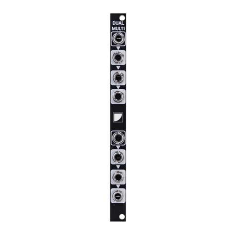
BLACK NOISE DUAL MULTI Manual

BLACK NOISE

BLACK NOISE DUAL MULTI Manual

BLACK NOISE DRII User manual

BLACK NOISE

BLACK NOISE DRII User manual

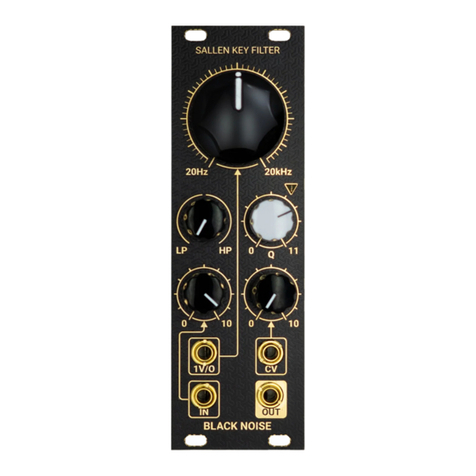
BLACK NOISE SALLEN KEY Manual

BLACK NOISE

BLACK NOISE SALLEN KEY Manual

BLACK NOISE DR II - S Manual

BLACK NOISE

BLACK NOISE DR II - S Manual

BLACK NOISE QBI User manual

BLACK NOISE

BLACK NOISE QBI User manual

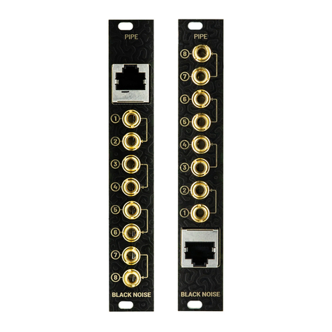
BLACK NOISE PIPE User manual

BLACK NOISE

BLACK NOISE PIPE User manual

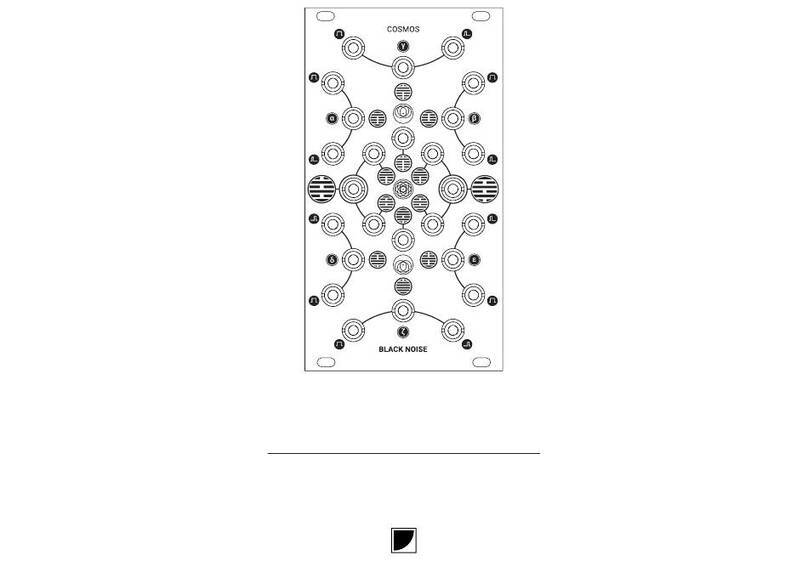
BLACK NOISE COSMOS Manual

BLACK NOISE

BLACK NOISE COSMOS Manual

BLACK NOISE GOMA Manual

BLACK NOISE

BLACK NOISE GOMA Manual

BLACK NOISE SALLEN KEY User manual

BLACK NOISE

BLACK NOISE SALLEN KEY User manual

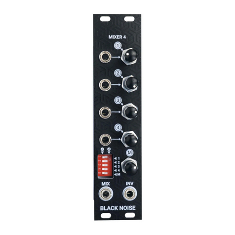
BLACK NOISE MIXER4 User manual

BLACK NOISE

BLACK NOISE MIXER4 User manual

BLACK NOISE SAM-C User manual

BLACK NOISE

BLACK NOISE SAM-C User manual

BLACK NOISE SAM-C Manual

BLACK NOISE

BLACK NOISE SAM-C Manual

BLACK NOISE Dual Rectifier II - S User manual

BLACK NOISE

BLACK NOISE Dual Rectifier II - S User manual

BLACK NOISE QBI Manual

BLACK NOISE

BLACK NOISE QBI Manual

BLACK NOISE DRII Manual

BLACK NOISE

BLACK NOISE DRII Manual

BLACK NOISE EG-LFO II User manual

BLACK NOISE

BLACK NOISE EG-LFO II User manual

Popular Recording Equipment manuals by other brands

Roland TR-707 owner's manual

Roland

Roland TR-707 owner's manual

Ateis UAPG2 G2 Full instruction guide

Ateis

Ateis UAPG2 G2 Full instruction guide

2hp Comp manual

2hp

2hp Comp manual

Benedini TBS Micro V2.0 manual

Benedini

Benedini TBS Micro V2.0 manual

TTS Talk-Tracker user guide

TTS

TTS Talk-Tracker user guide

Mitsubishi FX2N-32CCL-NP Hardware manual

Mitsubishi

Mitsubishi FX2N-32CCL-NP Hardware manual

Behringer FEEDBACK DESTROYER FBQ1000 quick start guide

Behringer

Behringer FEEDBACK DESTROYER FBQ1000 quick start guide

Data Video HS-550 manual

Data Video

Data Video HS-550 manual

STEINWAY LYNGDORF P200 installation manual

STEINWAY LYNGDORF

STEINWAY LYNGDORF P200 installation manual

PAC RSIC-SI-CRC EZ installation guide

PAC

PAC RSIC-SI-CRC EZ installation guide

Adeunis RF sigfox MODBUS MASTER ARF8240CA user guide

Adeunis RF

Adeunis RF sigfox MODBUS MASTER ARF8240CA user guide

Lowrance X-5 Operation Operation manual

Lowrance

Lowrance X-5 Operation Operation manual

Viessmann Vitocom 100 Installation and service instructions for contractors

Viessmann

Viessmann Vitocom 100 Installation and service instructions for contractors

Sennheiser UI 770 quick guide

Sennheiser

Sennheiser UI 770 quick guide

Korg Trinity series Parameter guide

Korg

Korg Trinity series Parameter guide

Phonocar 05963 installation instructions

Phonocar

Phonocar 05963 installation instructions

M-S Cash Drawer EP-125KSC instructions

M-S Cash Drawer

M-S Cash Drawer EP-125KSC instructions

Korg Pandora PX2 owner's manual

Korg

Korg Pandora PX2 owner's manual

manuals.online logo
manuals.online logoBrands
  • About & Mission
  • Contact us
  • Privacy Policy
  • Terms and Conditions

Copyright 2025 Manuals.Online. All Rights Reserved.