SMT Volaro Series 4 Stand User manual

PC450/HD450
Operator’s Manual
--
Volaro Series 4 Lift

Safety Notes
•
•
•
• “”
• only
• Do not’
• Do not
• Do not
• Do not
• Do not
• Do not
PARTS & SERVICE
SMT Health Systems
Phone: (218) 847-3386 Toll Free: (800) 725-7761
Toll Free Fax: (888) 385-2345
Email: [email protected]
1380 Legion Road, Detroit Lakes, MN 56501
Safe Working Loads
NOTE:“” “”

Volaro Lift/Transfer Assessment Form
Are you using the correct lift for your needs?
Patient Name _________________________ ID#_________________Room#_____
Assessment Completed by____________________________Date_____________
Lift(s) Required___________________________Sling Size___________________
Comments for PRN Use_______________________________________________
Assessment Updated by_____________________________ Date_____________
_____________________________Date_____________
Assessment Care Planned by_________________________Date_____________
--
--

-

•
•
5”
• -
•
•
•
•
•
-
• -1”
•
•
•
•
•
• 3”
• 4”
•
•
•
PC450/HD450 Specification Sheet

DL201S: DIVIDED LEG SLING
H301S: HAMMOCK SLING
TDL202S: TOILETING SLING
MESH SLINGS:
Volaro Lift Slings
Volaro Sling Laundering Instructions
• -
• -Low Heat Only -
• -
• No Bleach
Warning:
Warranty is VOID.


Selecting the Style and Size of Sling to be Used:
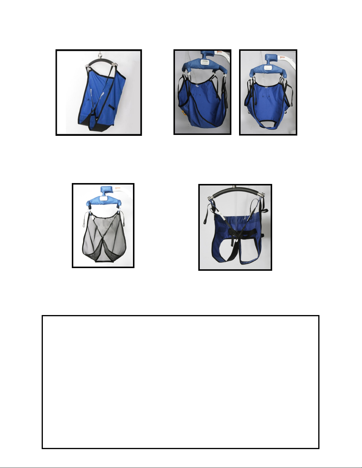
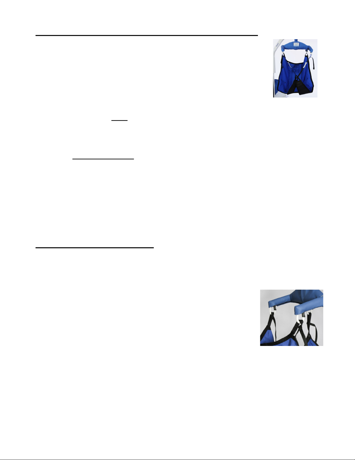
The first step is to select the Style of sling to be used. The most common
sling is the divided leg sling (shown). This sling is designed to be removed from
the person after they have been transferred into their wheelchair. This way they
do not have to sit on the sling throughout the time they are sitting in their chair.
If you find it difficult to remove a divided leg sling from behind a person while
they are seated in a wheelchair, you may choose to leave it behind/under them.
Be sure to observe the correct position of the sling before you lift the person.
The sling may have repositioned. If a person has leg discomfort while you use
the divided leg sling on them, another option would be the hammock sling. If you are lifting a single
or bilateral amputee, you must always use a hammock sling. The hammock sling comes with or
without the commode hole.
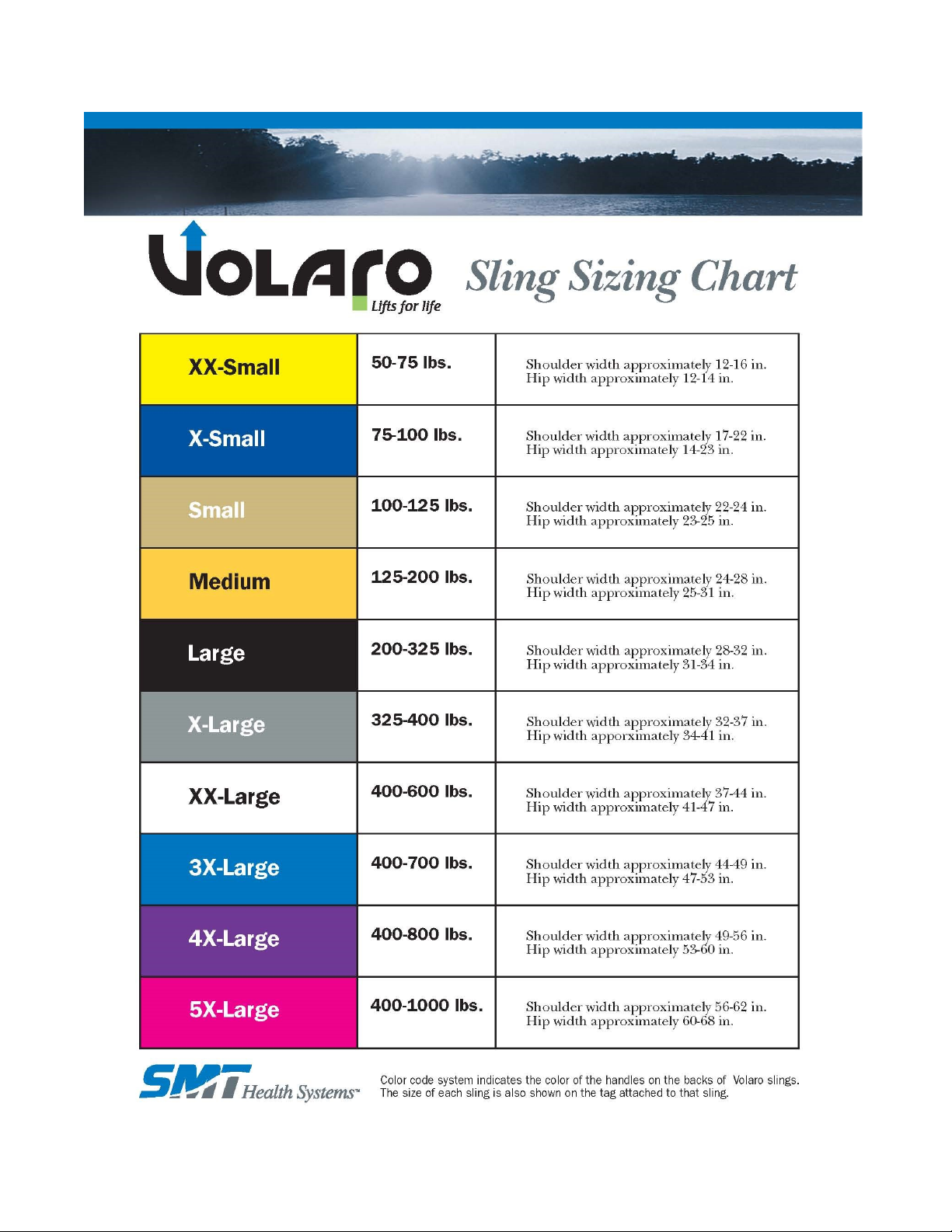
The second step is to determine the proper Size. Lay a sling across the persons chest. If
it’s the proper size sling, you will note 2-8 inches of extra material extended past the side of each
arm. NOTE: This is only a guide. Body shapes vary so much that fitting the patient to the
sling ultimately needs to be determined by the health care professional. If you observe
little or no fabric extended past the arms, you must upgrade to a larger sling. All styles have color
coded positioning handles to easily indicate the size of the sling. (Page 7) The loops on the straps
are color coded to match each side in positioning the sling to the desired location. Make sure you
use the same color loop on the “J” hook directly across from each other to keep the sling even.
Changing the orientation of these loops will change the angle of the person being transferred. This
comes in handy for charting the colors that would work best for each individual. All sling styles
come with built in positioning handles on the back of the sling. These always face out and are used
to position a person back in a chair.
Lifting from Chair to Bed:
To apply the divided leg sling on someone sitting in a wheelchair, first lean the person
slightly forward to get clearance between the back of the person and the back of the wheelchair.
Keeping the sling from twisting, using the pockets in the back of the sling, make sure the sling is all
the way down and that there is no gap behind the person. If the sling is not all the way down, it will
not come under the leg very easily. Work the sling alongside the legs,
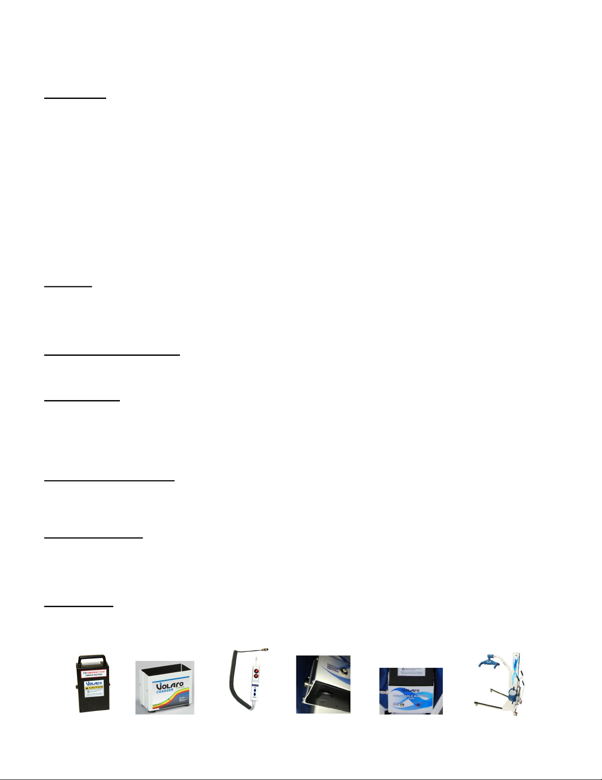
getting as much material toward the front of the chair as possible. Raise the
leg and pull the material through, preventing any wrinkles. Crisscross the
inside flaps with the main loops, then thread the strap with the color-coded
loops through the main loop. Crisscrossing the inside flaps will keep the legs
together for a more comfortable and dignified transfer. Now that the sling is
positioned, bring the lift toward the person, open the legs of the lift to the
wide position, lower the hanger until the desired colored loops can be
hooked on the hanger. Note: Raise until there is tension on the straps, then double check
to make sure sling loops are nested into the bottom of the hooks properly.
Now push the up button on the handle or use the hand control to raise the person just high enough
to clear the chair. Position the lift so that the person will be lowered to the proper position onto the
bed. Lower the lift. Once there is plenty of slack in the straps, remove the loops from the hanger
and pull the lift out of the way. Unthread the straps from the main loops. Roll the person on their
side and fold the sling, then roll to the other side and remove the sling.

Lifting from the Floor:
To transfer from the floor, apply the sling with the same procedure as if they were in bed. If
the person is on the floor as a result of a fall, no transfer should be attempted until it is de-
termined that there are no injuries. Once the sling is positioned under the person as if they were
lying in a bed, bring the lift up to the person being transferred from either the head or legs. If the lift is
brought in by the head, apply a pillow between the head and the base of the lift. (The reverse may be
done as well with the patient’s legs resting on pillows on the base of the lift.) Lower the lift to the lowest
position and hook up the front two straps to the hanger. You will need to use the two extension straps
supplied with the sling ( A). This strap loops through itself ( B ) in order to extend the head end of the
sling strap low enough for a floor lift. A second set of straps can be used to extend it further if neces-
sary. ( C ).
Push the lift as close to the patient as possible, then lock the brakes. (When bringing the lift in by the
legs, lift the legs onto the base, cushioning with pillows.) Now hook up the back two straps by bending
the knees and applying the loops to the hanger. All the models of slings come with straps on the foot
end that are long enough to transfer from the floor. Note: If you are using a sling without head support,
you will need to support the patient’s head with your hands.
Lifting from Bed to Chair using the Divided Leg Sling:
When transferring from bed to chair just reverse the steps in the previous instructions. Roll the
person to their side and lay the folded sling behind them. Align the bottom of the back of the sling by
the tailbone. Roll the person to their side and pull the rest of the sling through, straightening any
wrinkles. Bring material under the legs the same way as if they were in the chair. Crisscross the inside
flaps and thread the straps through the main loops. Bring the lift in, adjust the base to the widest
position, and lower hanger near the center of the person being transferred. Keep the lift in the widest
position possible at all times, especially when transferring a person who is uncooperative or combative.
Bend the knees and hook up the color coded loops that were previously used to bring them to a sitting
position. Press the button to raise the lift just high enough to clear the bed and make sure the material
under the leg stays straight toward the knee, keeping out as many wrinkles as possible. Note: Raise
until there is tension on the straps and then double-check to make sure the loops are nested
in the bottom of the hooks. If the base is in the narrow position, adjust it to the widest po-
sition once you are clear from the bed and always before turning the lift. Once the patient is
over the chair, lower and guide them by the built-in handles on the sling to bring them back far into the
chair. Note: Use only the lift handle bars to move the lift. Pulling or pushing on the person or
the beam will cause the lift to be unstable. To remove the sling, reverse the step. Unthread the
straps from the main loops, raise the legs and pull the material aside. Now lean the person forward and
pull sling clear.

Power Pacs:
NOTE: Power pac removal is your emergency stop feature.
-
-
Switches:
-
Emergency Down Feature:
Power Failure:
5/16” 3/8”
Manual Down Operation:
Width Adjustment:
Wheel Locks:
Mechanical Operation

Hanging and Dual Display Scale
Calibration Instructions
PC450/HD450
“ON/ZERO”
“ON/ZERO”“LB/KG”
“ZERO”“CAL”.
“C O”.
“ON/ZERO”
“16” to “0”.“C 25”.
“ON/ZERO”“16”“0”
“25”
Do not touch lift while it is counting down
“ON/ZERO”
Note:
Call SMT Customer Service if you have any questions. 800-725-7761

Charging Procedure
Note:
❑
❑
❑
❑
❑
❑
❑
Additional charging information
bulk charge
ramping charge (absorption
mode)
temperature compensated float charge
Maintaining the proper power pac voltage when
the power pac is not in use will extend the serviceable life of the power pac.
SMT Health Systems, Inc.
1380 Legion Road
Detroit Lakes, MN 56501
Phone: (218) 847-3386 ● (800) 725-7761
Fax: (888) 385-2345
Email: sales@smthealthsystems.com
SMT Volaro 12V Power Pac Charging

WEIGHING WITH ELECTRONIC SCALE (optional)
❑ “ON/ZERO” “ ”
❑
❑ “ON/ZERO”
NOTE: Lbs. Kilos - LBKG
”CONV” Lbs
❑
NOTE
’
❑
NOTE: Be sure that you are not pulling on the hanger
❑ one minute.
VOLARO CHARGER SPECIFICATIONS
-
-
-
-
-


ITEM
#
QTY PART # DESCRIPTION
11NA HD Frame Assembly
21NA PC Frame Assembly
31NA Mast & Base Plate Assembly
42PC4003A Leg Assembly
5170635 Notch Plate (SN prior to A4000 uses # PC45020)
6110015-1Power Box Assembly (Does not include circuit board 10011-2.)
722293 Rear Caster Mount Cap
81PC45022 Safety Limit Switch
922196 / LT2046 4” rear caster (standard) or 5” high profile caster
10 22003 / 2034 3” dual front caster (standard) or 4” single high profile caster
11 1PC45005A Actuator Spring Mount
12 1PC45026 Mast Cap
13 1PC45027 Actuator Support Bushing
14 1PC45023-1Actuator Support Bushing Mount
15 170953 Non-Scale Beam (SN A6894 or older uses PC45031NS)
16 170953 Scaled Beam Assembly (SN A6894 or older uses PC45006A)
17 42013 Cam Follower
18 4PC45037 Carriage Glide Block
19 435237-1Nylatron Roller
20 12039 Actuator Assembly
21 1PC45008A Handle Bar Actuator Assembly
22 22008 Red Push Button Switch
23 1PC4509A-1Leg Adjuster Handle Assembly
24 135506-2Scale Cover (for Dual Display Scale in Beam)
25 42159 Saddle Bag Strap Retainer
26 235005-2Saddle Bag
27 22125 Mast Plug
28 12279 Mast Cap Plug
29 1PC45056 Lower Circuit Board Mount (Dual Display Scale Only)

ITEM
#
QTY PART # DESCRIPTION
30 1PC45057 Upper Circuit Board Mount (Dual Display Only)
31 12743 Scale Power pac Box (Dual Display Only)
32 12791 Scale Circuit Board (Dual Display Only)
33 1PC45060 Load Cell (Dual Display Only)
34 1PC45031-1Non-scale adaptor (Dual Display Only)
35 12087 Counter Balance Spring
36 235022-1Mast Brush Holder (Older gray models only)
37 235021-1Mast Brush
38 2PC4511A Leg Adjuster Linkage Assembly
39 2PC45065-1Leg Bumper – Color _____________
40 150178-1Actuator Mount Bushing
41 110006-A3 Charger Assembly (includes 2026 transformer)
42 110047-2Hand Control (Remote)
43 235506-2Scale Face Plate (Dual Display)
44 1PL10004A Hanger Assembly (not including padding and covers)
45/46 170756 Strap Retainer and Spring Kit (set of 4)
47 22033 Hanger Thrust Bearing
48 22035 Leg Bearing
49 1PP40053-1Leg Adjuster Spring (Urethane)
50 1PA62201-1Hand Control (Remote) Holder
51 1PL44000-2Hanger Cover Center – Color _______________
52 2PL44001 Hanger End Cover - Color _______________
53 1PL44002 Beam End Cover - Color _______________
54 110048-212V Power pac Assembly
55 12026 Wall Transformer (White)
56 12272 Square End Cap
57 12006 -Adjuster Handle Grip -1 Black, -2 Blue
58 22002 -Handle Bar Grip -1 Black, -2 Blue

2
4
6
8
1
3
5
7
NOTE: Do not pull plug out by wires, this could loosen/damage them.
Circuit Board Wiring Diagram

Volaro Series 4 Lift
Problem Cause Solution
Lift
’
Actuator
Power Pac
Power Pac Charger
Scale
2. “” “”

-’
-
(This for should be copied for each operator and kept with their
personnel records.)
Volaro PC450/HD450
General Procedure Guide for Training
Yes No

Yes No
“”
“” “”
CAUTION: Push and turn the lift from the handles only. Pushing on the top of the
beam or on the resident could jeopardize the lift’s stability.
Other manuals for Volaro Series 4 Stand
1
This manual suits for next models
2
Table of contents