C
Fiber optic connection:
Take care when mating connectors with the units, all
beroptic connectors are polarized and should never be
forced.
Fiber cable
Ready made Fiberoptic cable assemblies, terminated
with IP67 rated, polarized, Huber&Suhner Q-ODC con-
nectors, are normally ordered from SMW with the system.
They available in several standard lengthsand can also
be supplied in customized lengths and with other termina-
tions like Q-ODC to FC-APC, Q-ODC to LC-APC or
Q-ODC to SC-APC.
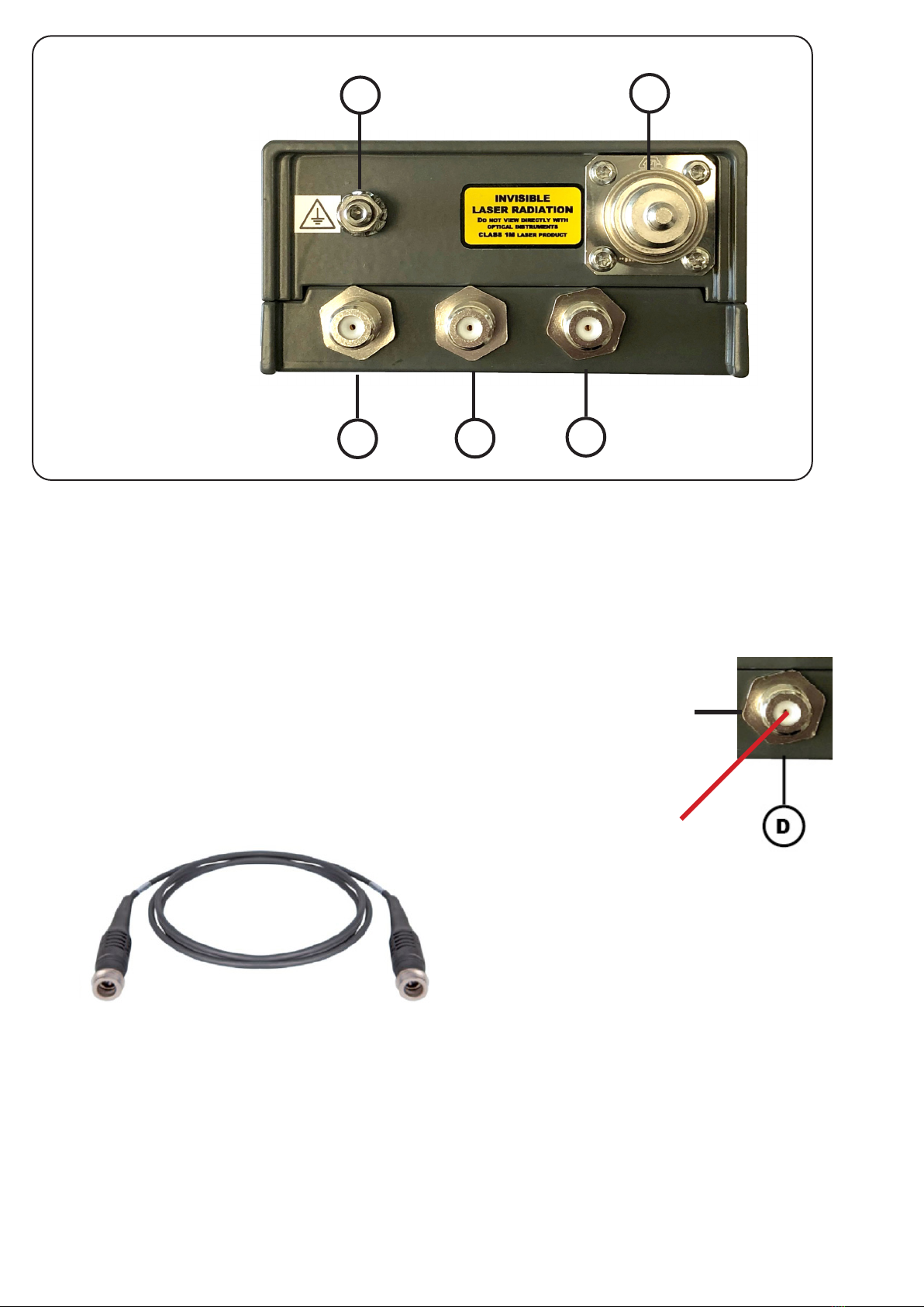
A
RF / L-band connector
Your unit is equipped with one L-band connection.
Connectors are type F (option N).
• On the LNB-LINK, connect your LNB. DC power
from the DC power input (D, g 3) is fed through to
RF / L-band connector for powering the LNB. Rating
is max 1A for LNB, short circuit protected
• On the Receiver Rx, connect your RF signal receiver
for SAT signals from the LNB.
B
RF Monitor output
The RF Monitor output have a -20 dB attenuation compa-
red with the RF connector to be used for
control or measuring the level of the RF signal
Cleaning is essential!
The information carrying ber core is 9 µm in
diameter, approx. a tenth of the human hair, so
ber-optic connections are very sensitive to
impurities on the ber ends. Impurities such as dust,
bers from clothes, ngerprints etc will result in
degradation of system performance or system error.
Cleaning with an appropriate cleaning tool, such as
a “Click Pen”, is strongly recommended EVERY
TIME before reconnecting a beroptic cable.
The IBC brand “Click Pen” should be a part of any
installers’ tool kit and is available from SMW (p/n
280505-01) or can purchased locally from a well
stocked Fiberoptic supplier.
Please also refer to Huber&Suhner Application Note
”Cleaning of Fiber-optic connectors” which can be
ordered free of charge from SMW.
5
Fig. 5
Fig. 6
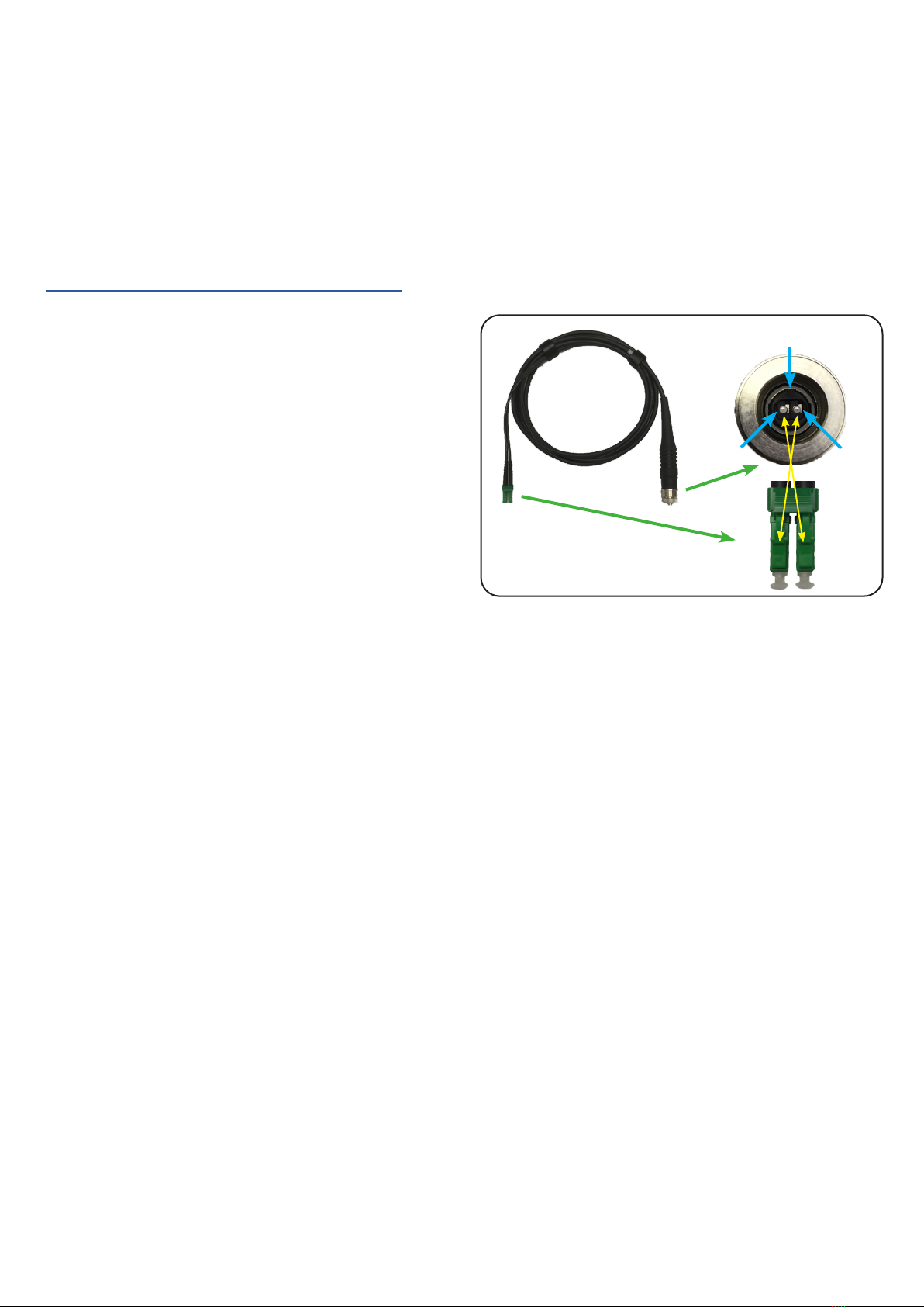
Connecting
Take care when mating the Q-ODC connectors with the
units, Q-ODC connectors are polarized and should never
be forced on.
MATE: Push cable plug gently into connector, rotate (a)
to nd keying position, push connector (b) until ”click” to
mate (Fig. 7).
UNMATE: Pull coupling ring to unmate(Fig. 5,6).
Fig. 7
(b)
click
(a)