DINGLI JCPT0607DCS User manual
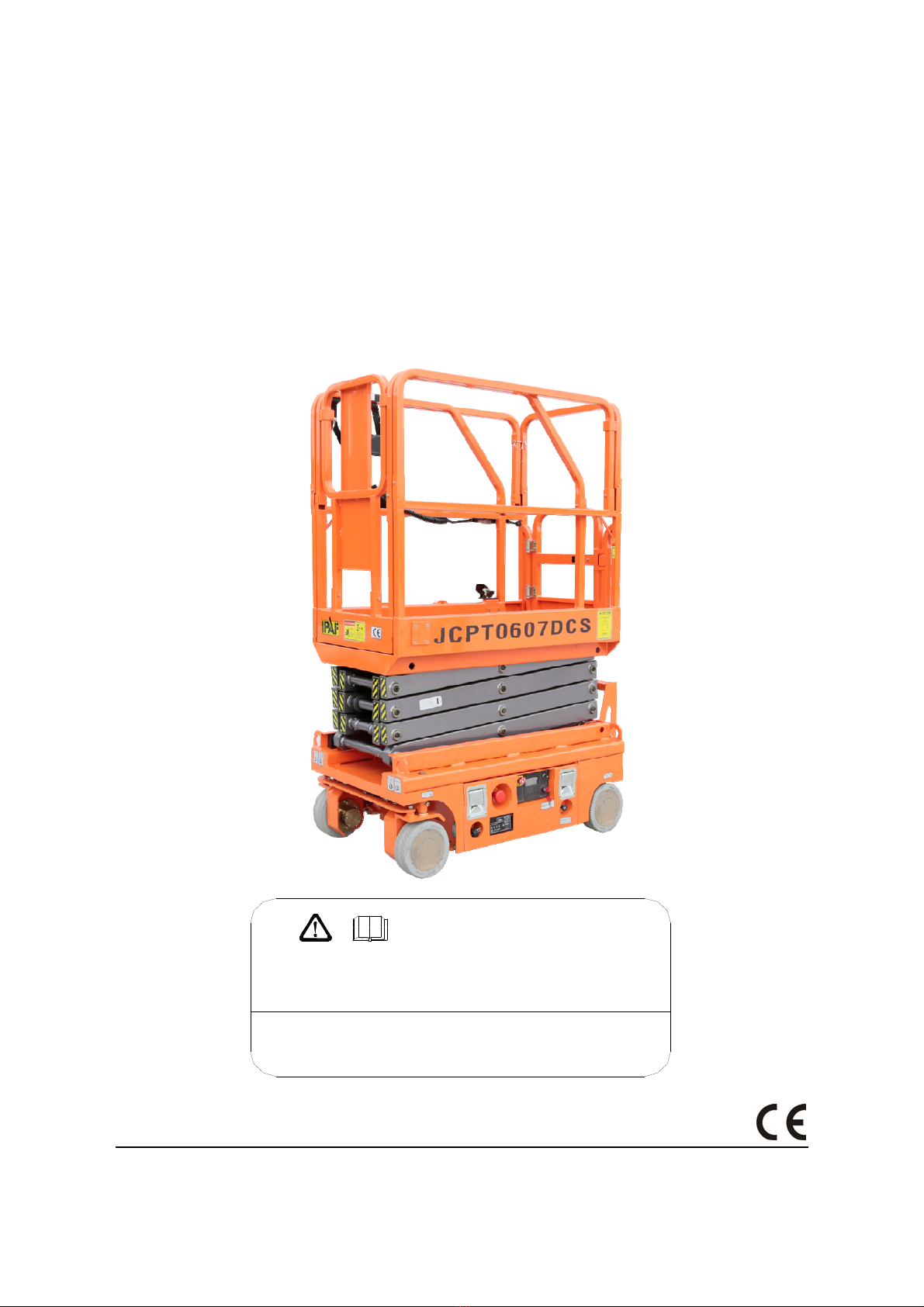
SELF-PROPELLED SCISSOR LIFTS
OPERATOR’S MANUAL
with Maintenance Information and Parts List
( For JCPT0607DCS )
Part Number: SM0115111
Zhejiang Dingli Machinery Co., Ltd. First Edition, November 2015 Printing
WARNING
THE MANUFACTURER SHALL NOT BE HELD LIABLE IN CASE OF FAULTS
OR ACCIDENTS DUE TO NEGLIGENCE, INCAPACITY, INSTALLATION BY
UNQUALIFIED TECHNICIANS AND IMPROPER USE OF THE MACHINE
DO NOT OPERATE THIS MACHINE UNTIL YOU READ AND UNDERSTAND
ALL THE DANGERS,WARNINGS AND CAUTIONS IN THIS MANUAL

OPERATOR’S MANUAL with Maintenance Information
Version of the Record
i
Version of the Record
VersionNumber Create Date
SM0115111_Rev1.0 …………………………………………………………………………… 2015-11


OPERATOR’S MANUAL with Maintenance Information
i
Important
Read, understand and obey these safety rules
and operating instructions before operating
this machine.
Only trained and authorized personnel shall be
permitted to operate this machine. This
manual should be considered a permanent
part of your machine and should remain with
the machine at all times. If you have any
questions, please call DINGLI Machinery.
Contents
Page
Safety Rules 1
Legend 7
Decals 8
Specifications 11
Control panel 12
Pre-Operating Instructions 15
Workplace Inspection 17
Function Tests 18
Operating Instructions 22
Transport and Lifting Instructions 33
Maintenance 35
Schematic 55
Inspection and Repair Log 57
Owners, Users and operators:
We appreciate your choice of our machine for
your application. Our number one priority is
user safety, which is best achieved by our joint
efforts. We feel that you make a major
contribution to safety if you, as the equipment
users and operators:
1 Comply with employer, job site and
governmental rules.
2 Read, understand and follow the
instructions in this and other manuals
supplied with this machine.
3 Use good safe work practices in a
commonsense way.
4 Only have trained / certified operators,
directed by informed and knowledgeable
supervision, running the machine.
If there is anything in this manual that is not
clear or which you believe should be added,
please contact us.
Contact us:
Zhejiang Dingli Machinery Co., Ltd.
1255 Baiyun South Road. Leidian Town.
Deqing Zhejiang
China
Tel: +86-572-8681688
Fax: +86-572-8681690
Web: www.cndingli.com
E-mail:[email protected]

OPERATOR’S MANUAL with Maintenance Information
Safety Rules
1
Danger
Failure to obey the instructions and
safety rules in this manual will
result in death or serious injury.
Do Not Operate Unless:
√You learn and practice the principles of
safe machine operation contained in this
operator's manual.
1 Avoid hazardous situations.
Know and understand the safety rules
before going on to the next section.
2 Always perform a pre-operation
inspection.
3 Always perform function tests prior to
use.
4 Inspect the workplace.
5 Only use the machine as it was
intended.
√You read, understand and obey the
manufacturer's instructions and safety
rules— safety and operator's manuals and
machine decals.
√You read, understand and obey employer's
safety rules and worksite regulations.
√You read, understand and obey all
applicable governmental regulations.
√You are properly trained to safely operate
the machine.
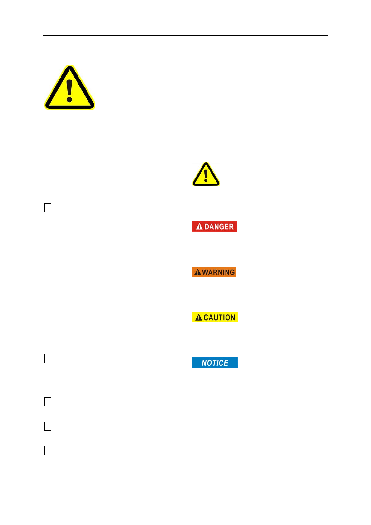
Decal Legend
DINGLI product decals use symbols, color
coding and signal words to identify the
following:
Safety alert symbol—used to alert
personnel to potential personal injury hazards.
Obey all safety messages that follow this
symbol to avoid possible injury or death.
Red—used to indicate the
presence of an imminently hazardous situation
which, if not avoided, will result in death or
serious injury.
Orange—used to indicate the
presence of a potentially hazardous situation
which, if not avoided, could result in death or
serious injury.
Yellow with safety alert
symbol- used to indicate the presence of a
potentially hazardous situation which, if not
avoided, may cause minor or moderate injury.
Blue without safety alert
symbol- used to indicate the presence of a
potentially hazardous situation which, if not
avoided, may result in property damage.
OPERATOR’S MANUAL with Maintenance Information
Safety Rules
2
Intended Use
This machine is intended to be used only to lift
personnel, along with their tools and materials
to an aerial work site.
Safety Sign Maintenance
Replace any missing or damaged safety signs.
Keep operator safety in mind at all times. Use
mild soap and water to clean safety signs. Do
not use solvent-based cleaners because they
may damage the safety sign material.
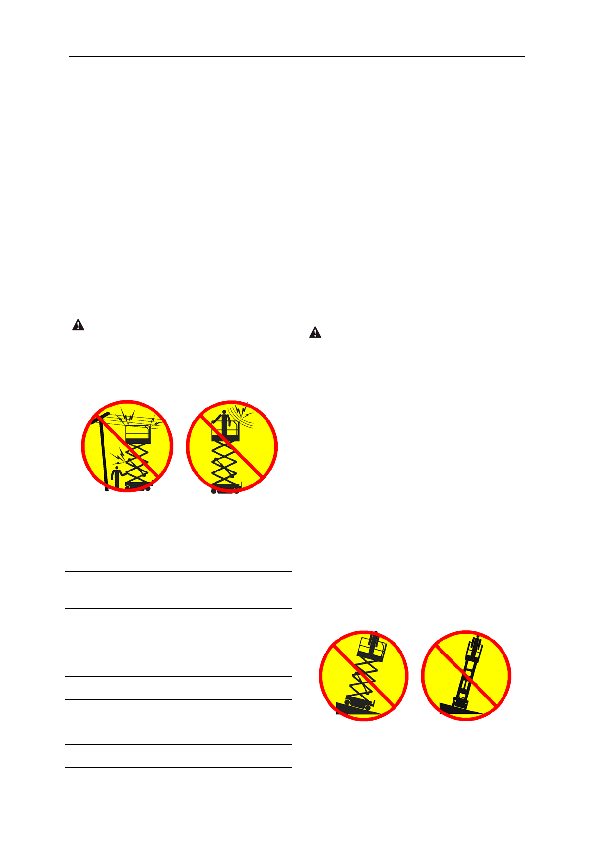
Electrocution Hazard
This machine is not electrically insulated and
will not provide protection from contact with or
proximity to electrical current.
Maintain safe distances from electrical power
lines and apparatus in accordance with
applicable governmental regulations and the
following chart.
Voltage
Phase to Phase
Minimum Safe
Approach Distance
0 to 300V Avoid Contact
300V to 50kV 3.05m
50kV to 200kV 4.60m
200kV to 350kV 6.10m
350kV to 500kV 7.62m
500kV to 750kV 10.67m
750kV to 1000kV 13.72m
Allow for platform movement, electrical line
sway or sag and beware of strong or gusty
winds.
Keep away from the machine if it contacts
energized power lines. Personnel on the
ground or in the platform must not touch or
operate the machine until energized power
lines are shut off.
Do not operate the machine during lightning or
storms.
Do not use the machine as a ground for
welding.
Tip-over Hazard
Occupants, equipment and materials must not
exceed the maximum platform capacity or the
maximum capacity of the platform extension.
Maximum capacity – JCPT0607DCS
Maximum occupants (Indoor use) 2
Maximum occupants (Outdoor use) 1
Platform allowable maximum load 240 kg
Extension deck allowable maximum load 100kg
Work Area Safety
Do not raise the platform unless the machine
is on a firm, level surface.
Do not drive over 1.1 km/h with the platform
raised.
Do not depend on the tilt alarm as a level
indicator. The tilt alarm sounds on the chassis
and in the platform when the machine is on a
OPERATOR’S MANUAL with Maintenance Information
Safety Rules
3
slope.
If the tilt alarm sounds:
Lower the platform. Move the machine to a
firm, level surface. If the tilt alarm sounds
when the platform is raised, use extreme
caution to lower the platform.
For outdoor use machine, do not raise the
platform when wind speeds may exceed 12.5
m/s. If wind speeds exceed 12.5 m/s when the
platform is raised, lower the platform and do
not continue to operate the machine.
Do not operate the machine in strong or gusty
winds. Do not increase the surface area of the
platform or the load. Increasing the area
exposed to the wind will decrease machine
stability.
Do not use the platform controls to free a
platform that is caught, snagged or otherwise
prevented from normal motion by an adjacent
structure. All personnel must be removed from
the platform before attempting to free the
platform using the ground controls.
Use extreme care and slow speeds while
driving the machine in the stowed position
across uneven terrain, debris, unstable or
slippery surfaces and near holes and
drop-offs.
Do not drive the machine on or near uneven
terrain, unstable surfaces or other hazardous
conditions with the platform raised.
Do not push off or pull toward any object
outside of the platform.
Maximum allowable manual force
Model Application
manual
force
Maximum
occupants
JCPT0607DCS
Outdoor 200N 1
Indoor 400N 2
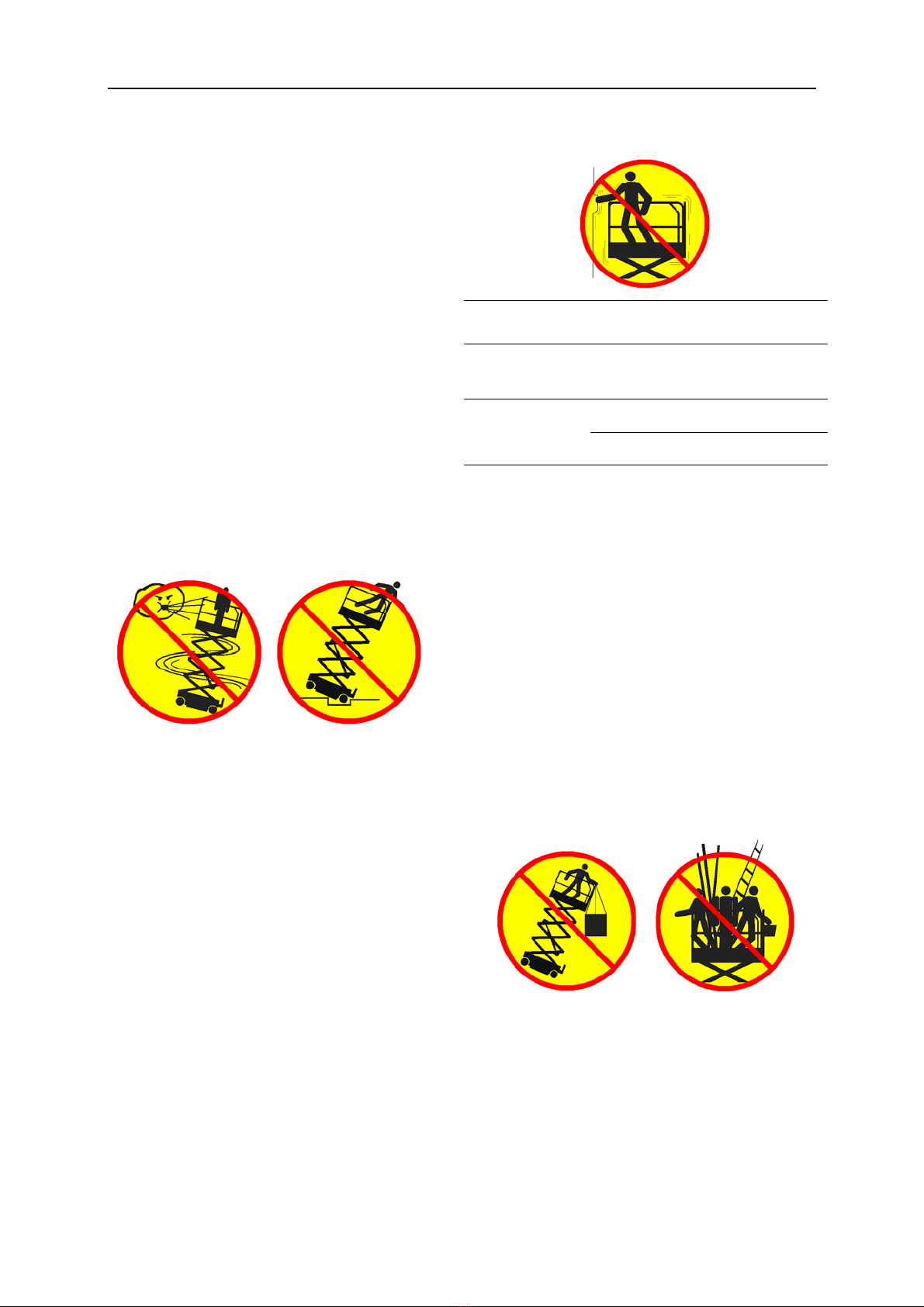
Do not use the machine as a crane.
Do not place or attach fixed or overhanging
loads to any part of this machine.
Do not push the machine or other objects with
the platform.
Do not operate the machine with the chassis
trays open.
Do not contact adjacent structures with the
platform.
Do not alter or disable the limit switches.
Do not tie the platform to adjacent structures.
Do not place loads outside the platform
perimeter.
Do not alter or disable machine components
that in any way affect safety and stability.
Do not replace items critical to machine
stability with items of different weight or
specification.
Do not use batteries that weigh less than the
original equipment. Batteries are used as
counterweight and are critical to machine
OPERATOR’S MANUAL with Maintenance Information
Safety Rules
4
stability. Each battery must weigh 25 kg. The
batteries must weigh a minimum of 50 kg.
Do not modify or alter an aerial work platform
without prior written permission from the
manufacturer. Mounting attachments for
holding tools or other materials onto the
platform, toe boards or guard rail system can
increase the weight in the platform and the
surface area of the platform or the load.
Do not place ladders or scaffolds in the
platform or against any part of this machine.
Do not transport tools and materials unless
they are evenly distributed and can be safely
handled by person(s) in the platform.
Do not use the machine on a moving or mobile
surface or vehicle.
Be sure all tires are in good condition and lug
nuts are properly tightened.
Crushing Hazard
Keep hands and limbs out of scissors.
Keep hands clear when folding rails.
Use common sense and planning when
operating the machine with the controller from
the ground. Maintain safe distances between
the operator, the machine and fixed objects.
Maintain a firm grasp on the platform rail when
removing the rail pins. Do not allow the
platform guard rails to fall.
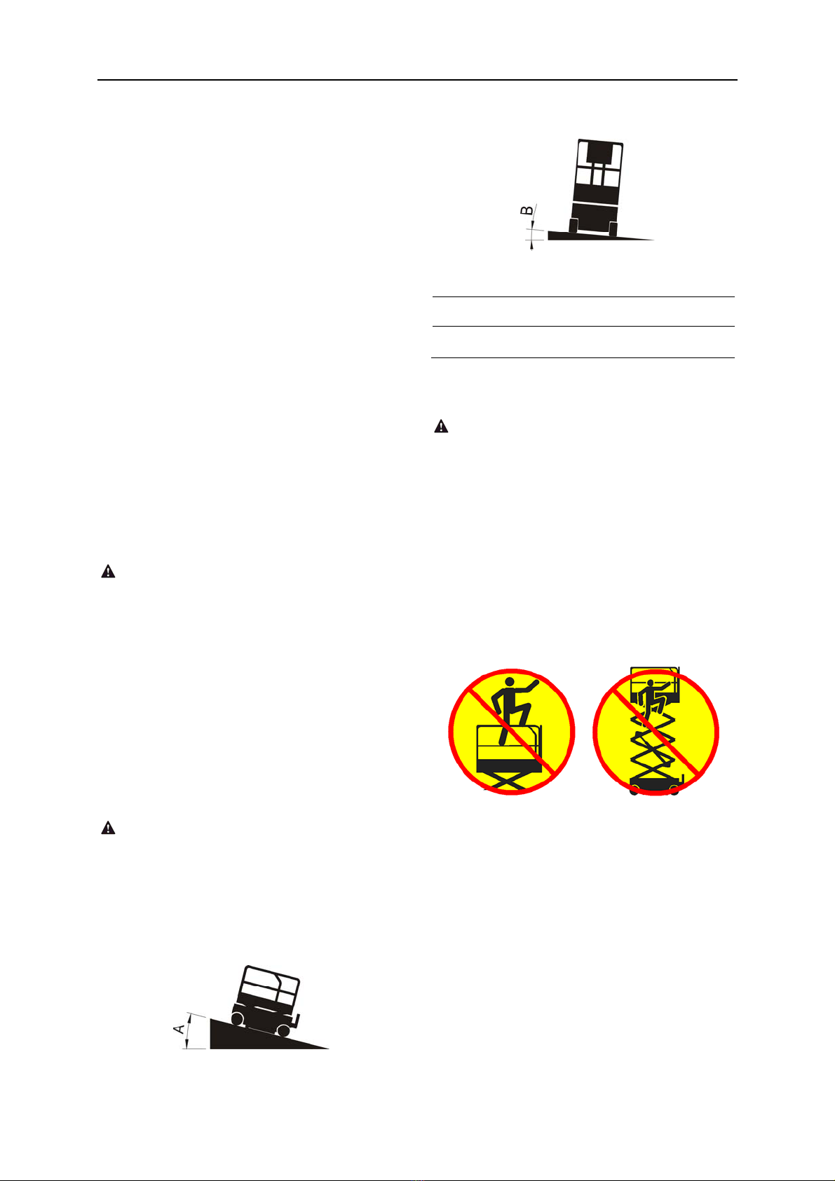
Operation on Slopes Hazard
Do not drive the machine on a slope that
exceeds the slope and side slope rating of the
machine.
Slope rating applies to machines in the stowed
position.
Maximum slope rating stowed
Maximum side slope rating stowed
Model AB
JCPT0607DCS 25% (14°) 25% (14°)
Note: Slope rating is subject to ground
conditions and adequate traction.
Fall Hazard
The guard rail system provides fall protection.
During operation, occupants in the platform
must wear a full body harness with a lanyard
attached to an authorized lanyard anchorage
point. Attach only one (1) lanyard per lanyard
anchorage point.
Do not sit, stand or climb on the platform guard
rails. Maintain a firm footing on the platform
floor at all times.
Do not climb down from the platform when
raised.
Keep the platform floor clear of debris.
Close the entry gate before operating.
Do not operate the machine unless the guard
rails are properly installed and the entry is
secured for operation.
Do not operate the machine the entry gate is
secured for operation.
OPERATOR’S MANUAL with Maintenance Information
Safety Rules
5
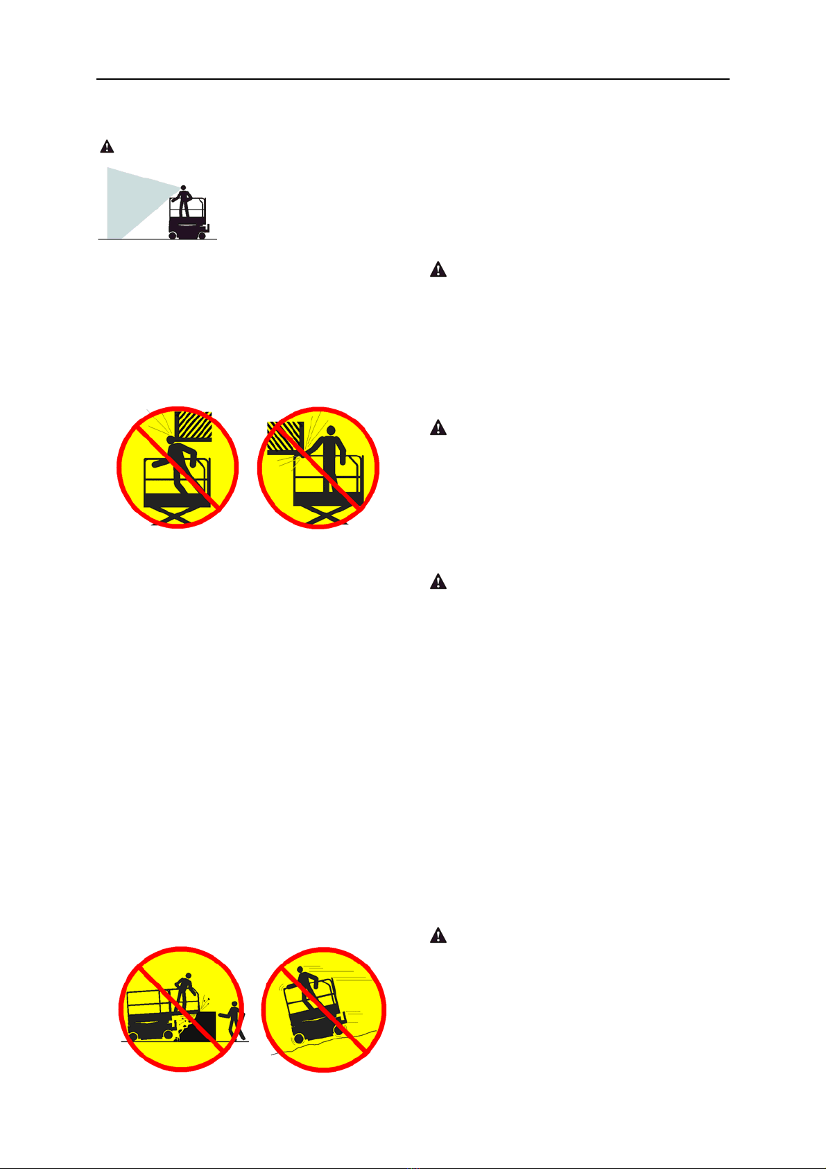
Collision Hazard
Be aware of limited sight distance and blind
spots when driving or operating.
Be aware of extended platform position(s)
when moving the machine.
Check the work area for overhead obstructions
or other possible hazards.
Be aware of crushing hazards when grasping
the platform guard rail.
Operators must comply with employer, job site
and governmental rules regarding use of
personal protective equipment.
Observe and use color-coded direction arrows
on the platform controls and platform decal
plate for drive and steer functions.
Do not operate a machine in the path of any
crane or moving overhead machinery unless
the controls of the crane have been locked out
and/or precautions have been taken to prevent
any potential collision.
No stunt driving or horseplay while operating a
machine.
Do not lower the platform unless the area
below is clear of personnel and obstructions.
Limit travel speed according to the condition of
the ground surface, congestion, slope, location
of personnel, and any other factors which may
cause collision.
Component Damage Hazard
Do not use any battery or charger greater than
24V.
Do not use the machine as a ground for
welding.
Explosion and Fire Hazard
Do not operate the machine in hazardous
locations or locations where potentially
flammable or explosive gases or particles may
be present.
Damaged Machine Hazard
Do not use a damaged or malfunctioning
machine.
Conduct a thorough pre-operation inspection
of the machine and test all functions before
each work shift. Immediately tag and remove
from service a damaged or malfunctioning
machine.
Be sure all maintenance has been performed
as specified in this manual
Be sure all decals are in place and legible.
Be sure the manuals are complete, legible and
in the storage container located in the platform.
Crushing Hazard
Keep hands and limbs out of scissors.
Use common sense and planning when
operating the machine with the controller from
the ground. Maintain safe distances between
the operator, the machine and fixed objects.
OPERATOR’S MANUAL with Maintenance Information
Safety Rules
6
Bodily Injury Hazard
Do not operate the machine with a hydraulic oil
or air leak. An air leak or hydraulic leak can
penetrate and/or burn skin.
Improper contact with components under any
cover will cause serious injury. Only trained
maintenance personnel should access
compartments. Access by the operator is only
advised when performing a pre-operation
inspection. All compartments must remain
closed and secured during operation.
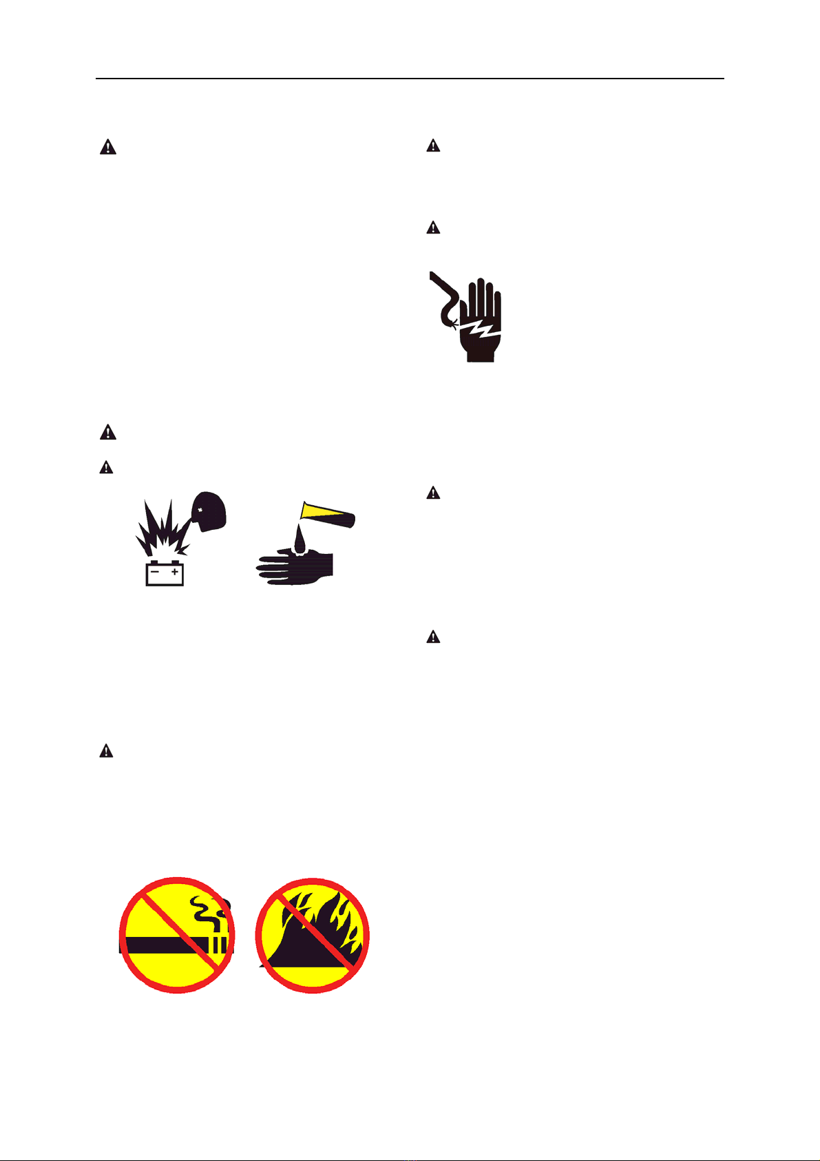
Battery Safety
Burn Hazard
Batteries contain acid. Always wear protective
clothing and eye wear when working with
batteries.
Avoid spilling or contacting battery acid.
Neutralize battery acid spills with baking soda
and water.
Explosion Hazard
Keep sparks, flames and lighted tobacco away
from batteries. Batteries emit explosive gas.
The battery tray should remain open during the
entire charging cycle.
Do not contact the battery terminals or the
cable clamps with tools that may cause
sparks.
Component Damage Hazard
Do not use any battery charger greater than
24V to charge the batteries.
Electrocution/ Burn Hazard
Connect the battery charger to
a grounded, AC 3-wire
electrical outlet only.
Inspect daily for damaged
cords, cables and wires.
Replace damaged items
before operating.
Avoid electrical shock from contact with
battery terminals. Remove all rings, watches
and other jewelry.
Tip-over Hazard
Do not use batteries that weigh less than the
original equipment. Batteries are used as
counterweight and are critical to machine
stability. Each battery must weigh 25 kg. The
batteries must weigh a minimum of 50 kg.
Lifting Hazard
Use the appropriate number of people and
proper lifting techniques when lifting batteries.
Lockout after Each Use
1 Select a safe parking location - firm level
surface, clear of obstruction and traffic.
2 Lower the platform.
3 Turn the key switch to the off position and
remove the key to secure from
unauthorized use.
4 Chock the wheels.
5 Charge the batteries.
OPERATOR’S MANUAL with Maintenance Information
Legend
7
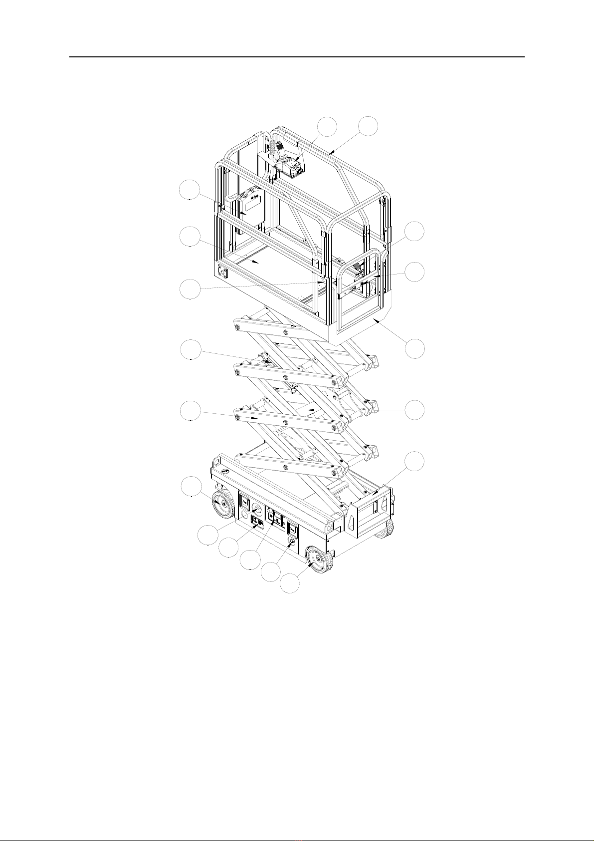
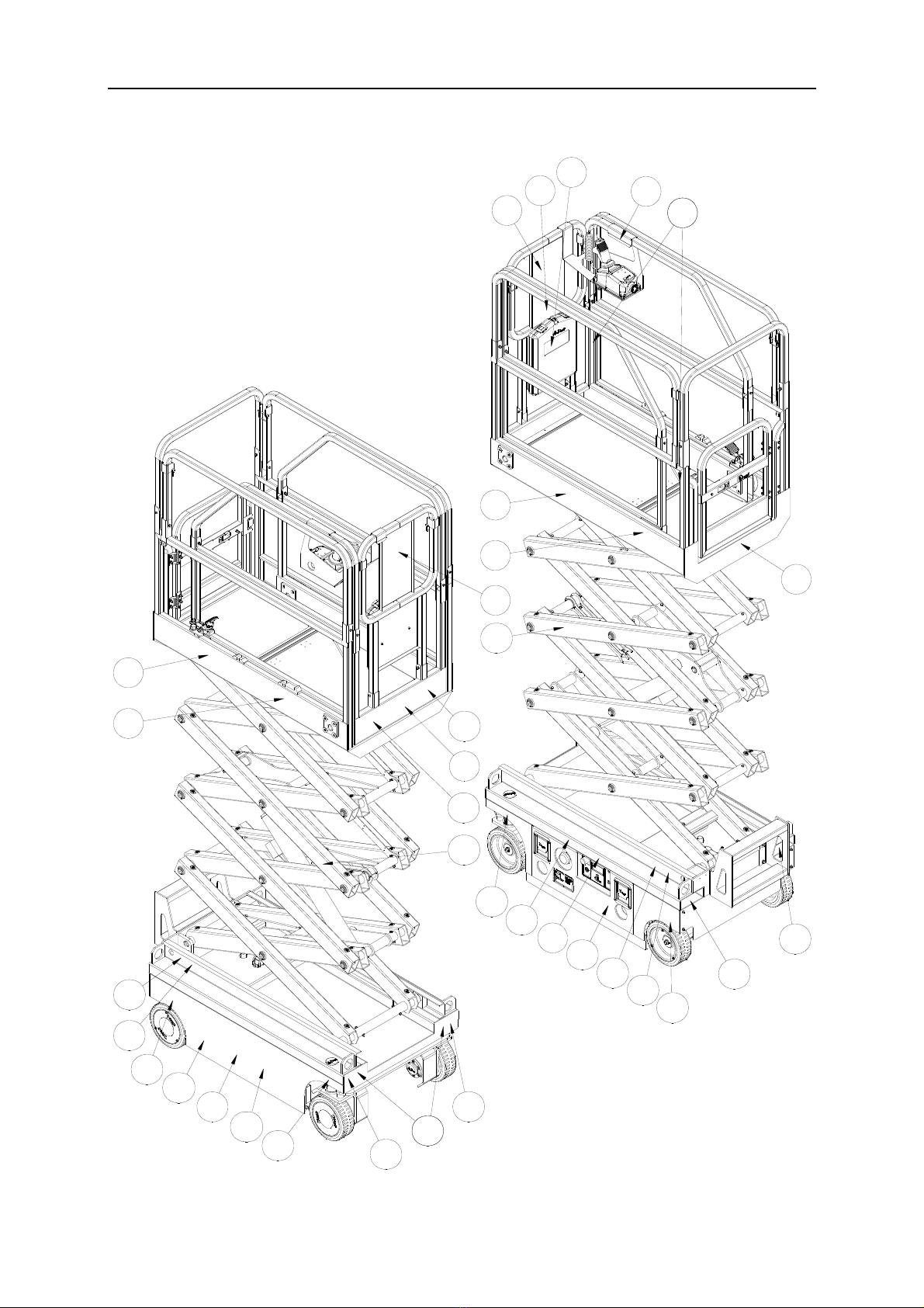
Legend
1 Platform controller
2 Platform guard rails
3 Platform extension release pedal
4 Platform entry gate
5 Main Platform
6 Lift Cylinder
7 Entry ladder
8 Drive wheels
9 Emergency lowering knob
10 Ground Control Panel
11 Batteries charger
12 Main power switch
13 Steer Wheels
14 Scissor
15 Safety arms
16 Lanyard anchorage point
17 Platform extension
18 Manual storage container
18
2
1
4
5
6
7
8
12
16
15
13
14
17 3
9
10
11

OPERATOR’S MANUAL with Maintenance Information
Decals
8
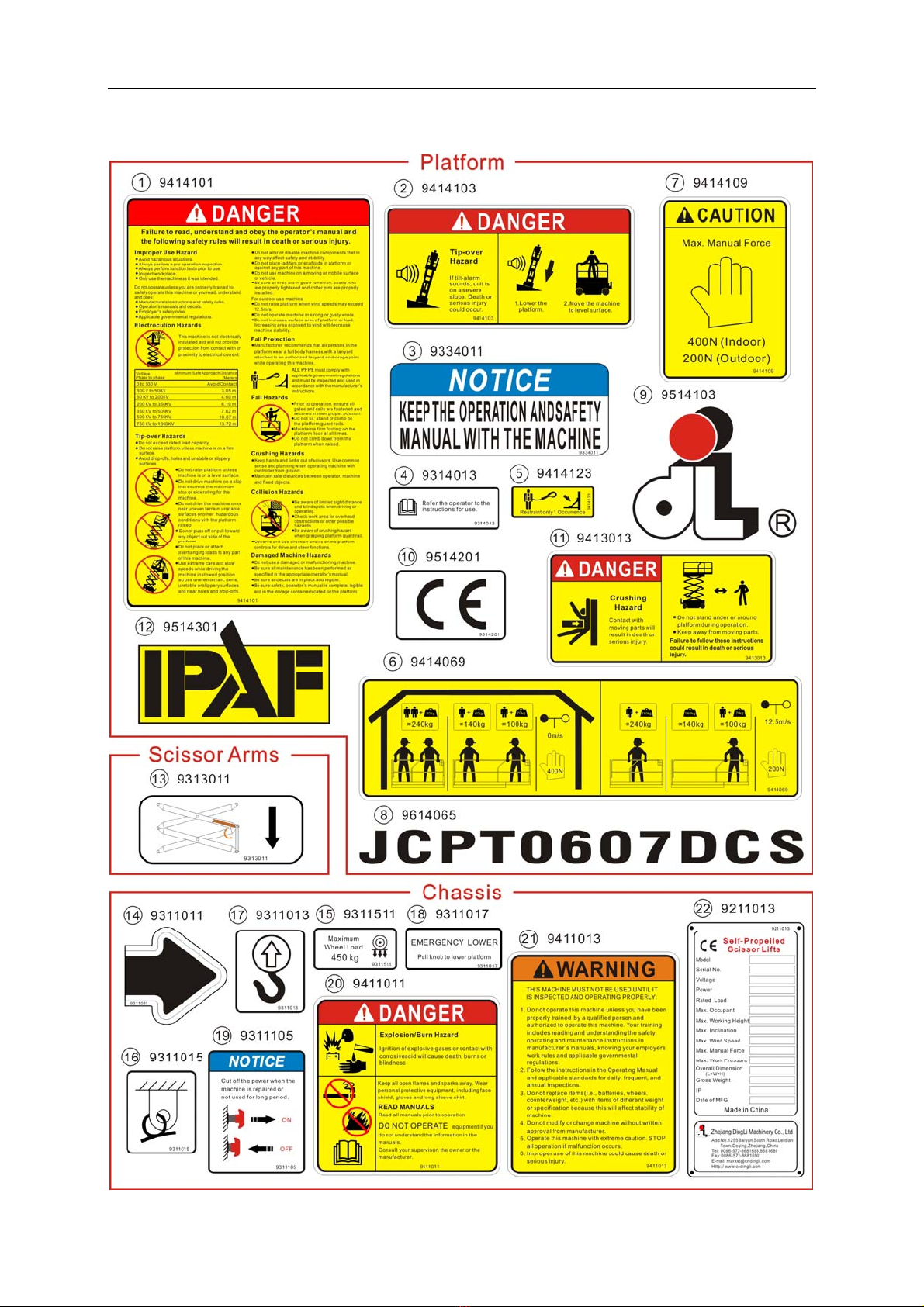
Decal Inspection
Use the pictures on the next page to verify that all decals are legible and in place.
Below is a numerical list with quantities and descriptions.
No. Part No. Description Qty. Remark
1 9414101 Danger – Safety rules 1
2 9414103 Danger – Tip-over hazard 1
3 9334011 Notice – Operator’s manual storage 1
4 9314013
Instructions – Refer the operator to the
instructions for use 2
5 9414123 Label – Lanyard anchorage 2
6 9414069 Label – Capacity 240kg 1
7 9414109
Caution – Max. manual force: 400N (Indoor)
200N (Outdoor) 2
8 9614065 Cosmetic – JCPT0607DCS 2
9 9514103 Cosmetic – Mark 1
10 9514201 Cosmetic – CE 1
11 9413013 Danger – Crushing hazard 1
12 9514301 Cosmetic – IPAF 1
13 9313011 Instructions – Safety arm 2
14 9311011 Instructions – Forklift pockets 4
15 9311027 Instructions – Wheel load: 450kg 4
16 9311015 Instructions – Tie down point 4
17 9311013 Instructions – Lift point 4
18 9311017 Instructions – Emergency lower 1
19 9311105 Notice – Main power switch operation 1
20 9411011 Danger – Explosion / burn hazard 1
21 9411013 Warning – Inspected and operation properly 1
22 9211013 Decal – Manufacturer's plate 1
OPERATOR’S MANUAL with Maintenance Information
Decals
9
11
1
2
3
4
55
6
7
8
9
10
12
13
13
17
16
14
14
15
18
15
17
16
17
16
20
22
15
17
16
21
4
7
8
15
19
OPERATOR’S MANUAL with Maintenance Information
Decals
10

OPERATOR’S MANUAL with Maintenance Information
Specifications
11
JCPT0607DCS
Height, working maximum 5.6 m
Height, platform maximum 3.6 m
Height, stowed maximum
Rails up
2.03 m
Height, stowed maximum
Rails lowered
1.67 m
Width 0.76 m
Length, platform retracted 1.44 m
Length, platform extended 2.04 m
Platform dimensions
Platform length × width 1.29×0.7 m
Platform extension length 0.6 m
Maximum load capacity 240 kg
Maximum wind speed 12.5 m/s
Wheelbase 1.05 m
Turning radius (outside) 1.55 m
Turning radius (inside) 0.4 m
Ground clearance 6 cm
Ground clearance
Pothole guards deployed
1.5cm
Weight 880kg
Machine weights vary with option configurations
Power source 2 Batteries , 12V 85Ah
Controls Proportional
AC outlet in platform Standard
Maximum hydraulic pressure
(functions)
155 bar
System voltage 24 V
Tire size Φ230×80 mm
Airborne noise emissions <70 dB
Maximum sound level at normal operating
workstations (A-weighted)
Vibration value does not exceed 2.5m/s
2
Maximum slope rating,
Stowed position 25%
Maximum side slope rating,
Stowed position 25%
Note: Slope rating is subject to ground
conditions and adequate traction.
Maximum working slope X-1.5°,Y-3°
Drive speeds
Stowed, maximum 4.0 km/h
Platform raised, maximum 1.1 km/h
Floor loading information
Tire load, maximum 450 kg
Tire contact pressure 10.9 kg/cm
2
1068.2 kPa
Occupied floor pressure 1143.3 kg/m
2
11.2 kPa
Note: Floor loading information is approximate
and does not incorporate different option
configurations. It should be used only with
ade
q
uate safet
y
factors.
Continuous improvement of our products is a
DINGLI policy. Product specifications are
subject to change without notice or obligation
OPERATOR’S MANUAL with Maintenance Information
Control Panel
12
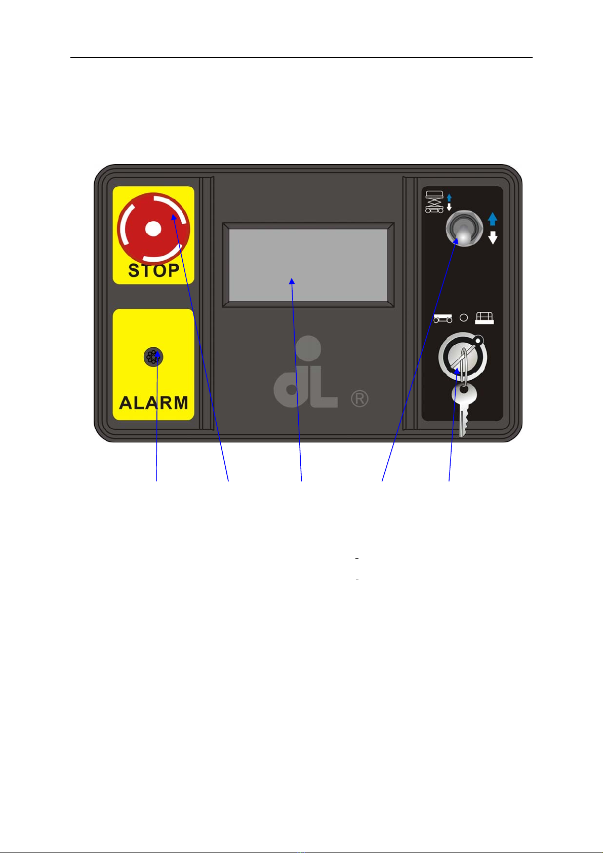
Ground Control Panel
1 Alarm
2 Red Emergency Stop button
Push in the red Emergency Stop button to the
off position to stop all functions. Pull out the
red Emergency Stop button to the on position
to operate the machine.
3 LED
4 Platform up / down Switch
Move the switch UP and the platform will raise.
Move the switch DOWN and the platform will
lower.
5 Key switch for platform / off / ground
control selection
Turn the key switch to the platform position
and the platform controls will operate. Turn the
key switch to the off position and the machine
will be off. Turn the key switch to the ground
position and the ground controls will operate.
○
1○
2○
3○
4○
5
OPERATOR’S MANUAL with Maintenance Information
Control Panel
13
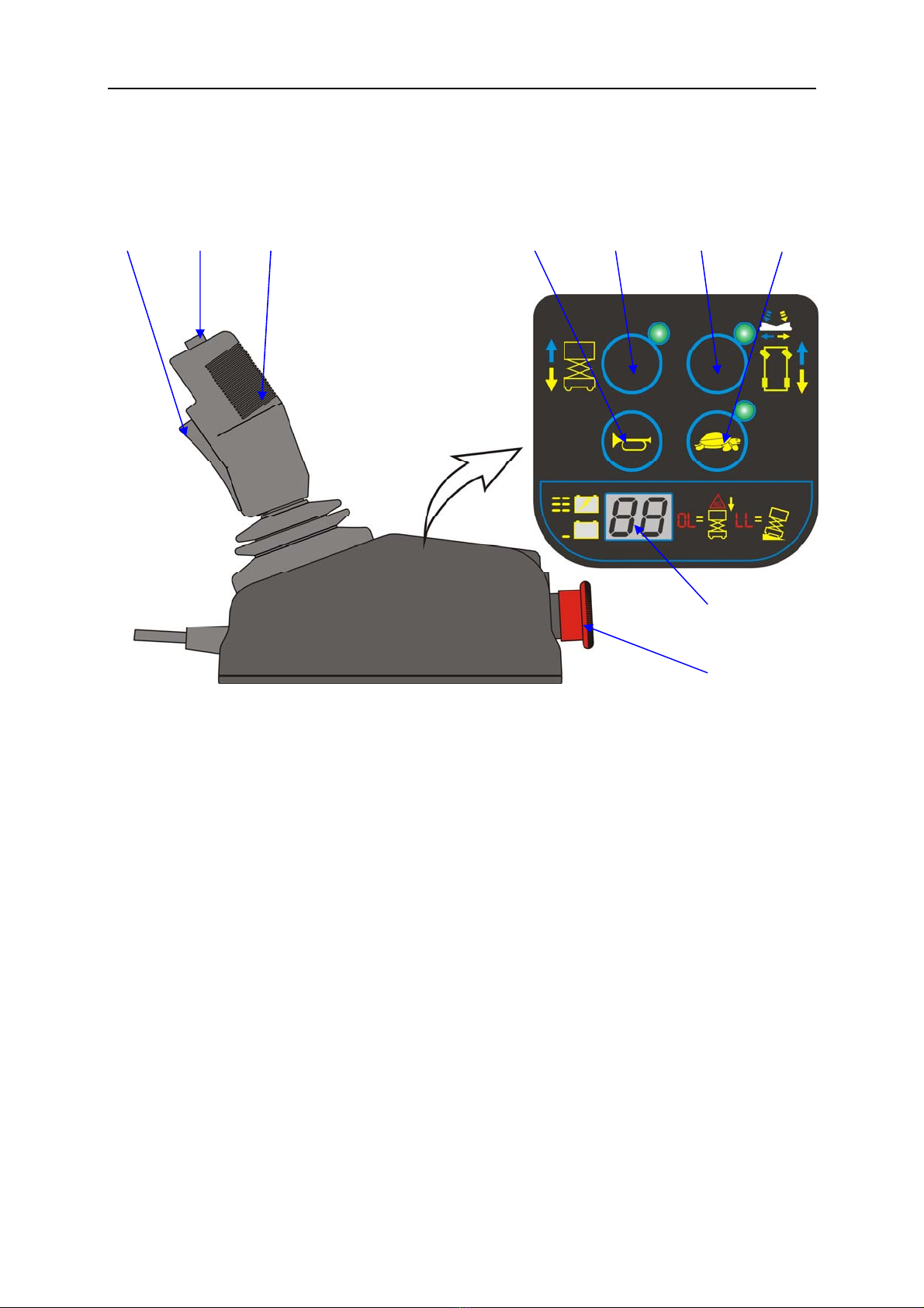
Platform Control Panel
1 Function enable switch for lift and
drive functions
2 Thumb rocker switch for steer
functions
3 Proportional control handle
4 Horn button
5 Lift function select button
6 Drive function select button
7 Drive speed button
8 LED
9 Red Emergency Stop button
○
8
○
9
○
1○
2○
3○
4○
5○
6○
7

OPERATOR’S MANUAL with Maintenance Information
Control Panel
14
Platform Control Panel
1 Function enable switch for lift and drive
functions
Lift function: Press and hold the function
enable switch to enable the lift function on
the platform control handle. Move the
control handle in the direction indicated by
the blue arrow and the platform will raise.
Move the control handle in the direction
indicated by the yellow arrow and the
platform will lower. The descent alarm
should sound while the platform is
lowering.
Drive function: Press and hold the
function enable switch to enable the drive
function on the platform control handle.
Move the control handle in the direction
indicated by the blue up arrow on the
control panel and the machine will move
in the direction that the blue arrow points.
Move the control handle in the direction
indicated by the yellow down arrow on the
control panel and the machine will move
in the direction that the yellow arrow
points.
Press and hold the function enable switch
to enable the drive function on the
platform control handle. Move the control
handle in the direction indicated by the
blue left arrow on the control panel and
the machine will turn to the lift direction
that the blue arrow points. Move the
control handle in the direction indicated by
the yellow right arrow on the control panel
and the machine will turn to right direction
that the yellow arrow points.
2 Thumb rocker switch for steer functions
Press the thumb rocker switch in either
direction to activate steer function.
3 Proportional control handle
4 Horn Button
Push the horn button and the horn will
sound. Release the horn button and the
horn will stop.
5 Lift function select button
Press this button to activate the lift
function.
6 Drive function select button
Press this button to activate the drive
function.
7 Drive speed button
Press this button to activate the slow or
fast drive function.
8 LED
Diagnostic read out and battery charge
indicator.
9 Red Emergency Stop button
Push in the red Emergency Stop button to
the off position to stop all functions. Pull
out the red Emergency Stop button to the
on position to operate the machine.

OPERATOR’S MANUAL with Maintenance Information
Pre-operation Inspection
15
Do Not Operate Unless:
√You learn and practice the principles of
safe machine operation contained in this
operator's manual.
1 Avoid hazardous situations.
2 Always perform a pre-operation
inspection.
Know and understand the pre-operation
inspection before going on to the next
section.
3 Inspect the workplace.
4 Always perform function tests prior to
use.
5 Only use the machine as it was
intended.
Fundamentals
It is the responsibility of the operator to
perform a pre-operation inspection and routine
maintenance.
The pre-operation inspection is a visual
inspection performed by the operator prior to
each work shift. The inspection is designed to
discover if anything is apparently wrong with a
machine before the operator performs the
function tests.
The pre-operation inspection also serves to
determine if routine maintenance procedures
are required. Only routine maintenance items
specified in this manual may be performed by
the operator.
Refer to the list on the next page and check
each of the items.
If damage or any unauthorized variation from
factory delivered condition is discovered, the
machine must be tagged and removed from
service.
Repairs to the machine may only be made by
a qualified service technician, according to the
manufacturer's specifications. After repairs are
completed, the operator must perform a
pre-operation inspection again before going on
to the function tests.
Scheduled maintenance inspections shall be
performed by qualified service technicians,
according to the manufacturer's specifications
and the manual.
Table of contents
Other DINGLI Scissor Lift manuals

DINGLI
DINGLI JCPT2223RT Setup guide

DINGLI
DINGLI E-TECH ACE Series Installation guide

DINGLI
DINGLI JCPT2223RTB Setup guide

DINGLI
DINGLI JCPT1523DC Setup guide

DINGLI
DINGLI S06-EH Setup guide

DINGLI
DINGLI JCPT DCS Series Installation guide

DINGLI
DINGLI S056-RS Setup guide

DINGLI
DINGLI JCPT0808 Setup guide

DINGLI
DINGLI S0608EH Setup guide

DINGLI
DINGLI SP039-E Setup guide


