manuals.online logo
Brands
  1. Home
  2. •
  3. Brands
  4. •
  5. Rotary
  6. •
  7. Scissor Lift
  8. •
  9. Rotary GLP99SM User manual

Rotary GLP99SM User manual

SCISSOR LIFT FREE WHEELS
GEMINI LOW PROFILE
OPERATING
INSTRUCTIONS
GLP99SM-GLP99SM/P
2
SCISSOR LIFT
EC DECLARATION OF CONFORMITY
The Company
ROTARY LIFT EUROPE S.r.l.
Via Tiburtina Km 209+800
65025 –MANOPPELLO SCALO –PESCARA (ITALIA)
Tel. 085/8569058-Fax 085/8569059
DECLARES ON ONE’S OWN RESPONSIBILITY THAT THE EQUIPMENT SPECIFIED BELOW:
TYPE OF EQUIPMENTS: SCISSOR LIFT FREE WHEELS
MODEL: GLP99SM •; GLP99SM/P •;
PART NUMBER: ..............................................
TO WHICH THIS DECLARATION IS RELATED, CONFORMS WITH THE FOLLOWING EUROPEAN
DIRECTIVES: 98/37/CEE - 73/23CEE- 93/68 CEE - 89/336
IT ALSO DECLARES THAT THE FOLLOWING EUROPEAN RULES HAVE BEEN RESPECTED :
EN 292.1- EN 292.2- EN294-EN 349- EN 1050- EN 60204-1. ETS 300 683 EN 55022B.
Name and address of the approval body: TÜV PRODUCT SERVICE - Zertifierstelle
Ridlerstrasse 31
D-80339 Munchen
Certificate number: M6 97 12 29366 004
Notifiziert bei der EG Kommission unter Nr. 0123
---------------------------------------------------------------------------- -------------------------------------------------------------------------
(Place and date) (Signature or stamp of the authorized person)
YEAR OF MANUFACTURE
VOLTAGE
220/380 Vac
220 Vac
240 Vac
110 Vac
Hz
50 Hz
60 Hz
AUTHORIZED SERVICE CENTER
3
CONTENTS
FIRST PART
Chapter 1-Introduction-packing-transport
page 3
Chapter 2-Machine description
page 4
Chapter 3-Safety
page 6
Chapter 4-Installation
page 7
Chapter 5-Operation
page 15
Chapter 6-Maintenance
page 16
Chapter 7-Troubleshooting
page 16
Chapter 8-Accessories
page 17
Chapter 9-Spare parts
page 17
SECOND PART
(For the use of installer)
Check book page 26
SYMBOLS

HAZARD-DANGER

PROHIBITED

WARNING
Follow the instruction given by the messages preceded by a safety alert symbol
CHAPTER 1- INTRODUCTION - PACKING –TRANSPORT
INTRODUCTION
This manual was written for shop technicians (car lift operators) and maintenance technicians. Before operating these car lifts, please
read these instructions completely. This manual gives helpful information about:
•Safety of people;
•Safety of the car lift;
•Safety of lifted car.
This manual is considered to be a permanent part of the lift and must be kept in an easily accessible place so that the operator can find
it and refer to it .A particularly careful reading of chapter “3” on safety is recommended.
All versions of “GLP99SM-GLP99SM/P” have been designed and built as required by:
EUROPEAN RECOMMENDATIONS: EEC 98/37/CEE, 73/23/CEE, 93/68/CEE, 89/336/CEE.
EUROPEAN RULES: EN 291/1992, EN 292/1992, EN 294, EN349, EN1050, EN 60204-1, EN 300683, EN 55022B.
Only skilled and previously authorized technicians should be allowed to carry out transport, assembling, setting, maintenance, overhaul,
moving, dismantling operations, etc. concerning the lift. The manufacturer is not responsible for possible damage to people, vehicles
and objects in the case that said operations are carried out by unauthorized personnel or the lift improperly used.
Read these instructions completely before operating the lift.
The lift must only be used for vehicles up to the specified capacity. Any inproper use of this lift is strictly forbidden
Disconnect the lift from the main electric supply before any extraordinary maintenance operation.
Lift installation must be carried out as specified by these instructions.
The manufacturer is not liable for possible damage resulting from failure to follow the instruction supplied with this car lift.
PACKING
Standard versions of the car lift are pre-assembled and equipped as follows:
2 x bases and platforms (p1-p2) placed on top of each other and sealed with pallet.
1 x control box.
1 x cardboard box equipped with hydraulic connections, rubber pads.
1 x set of lifting/lowering ramps.
MODELS
PACKING
A
B
C
KG.
GLP99SMP
1800
400
600
800
GLP99SM
1800
400
600
800
Control box
1000
400
500
75
cardboard box
400
300
200
10
ramps
1000
250
600
100
covers
(in ground version)
600
250
600
80
4
TRANSPORT
Packing can be lifted or moved by fork lift trucks, cranes or bridge cranes. In case of slinging, a second persons must always take care
of the load to avoid dangerous oscillations. At the arrival of goods, check for possible damage due to transport operations. Also verify
that all items specified in the delivery notes are included. In case of damage or possible defects in transit the person in charge or the
carrier must be immediately informed. Furthermore, during loading and unloading operations good must be handled as shown in the
picture.
PACKING REMOVAL
Wooden packing can be recycled , in case of packing removal,
comply with the applicable rules in the lift installation country.
CHAPTER 2- MACHINE DESCRIPTION MODELS-TECHNICAL SPECIFICATIONS
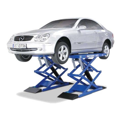
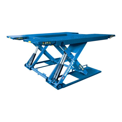
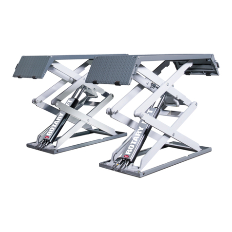
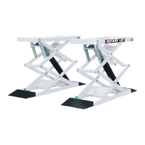
“GLP99SM” models are double scissor, low profile, (only 12 cm.), and fixed (that is anchored to the ground) car lifts and can be
delivered in both surface or recessed versions. They have been designed and built for car, van lifting and placing operations.
Our car lifts are equipped as follows:
A-BASE (Fixed structure)
B-BOOMS, PLATFORM (Lifting and travelling structure).
C-CONTROL BOX
M-serial number A-note
Fixed structure unit.
This is the car lift base, made of steel sheet with floor fixing holes.
Lifting and travelling structure unit.
This is composed of box-type steel sheet booms. The load carryng platform is made of longitudinal steel tubes linked to each other by
vertical rods anchored to the booms by steel pins at the fixed points, and by rollers at the movable ones. Lifting system links are
equipped with self-lubricating bushings where servicing is not required.
Control box.
The unit with a metallic box that contains oil tank, pump, motor, hand pump and electro-valve sets.There are also power and hydraulic
supply connections. Low-voltage controls (24V) are placed on the power unit. they are the following:
1.LIFTING PUSH BUTTON
2.LOWERING PUSH BUTTON
3.LIMIT SWITCH CUTOUT
4.LED
5.MASTER SWITCH
1- Lifting push button: When pressed, motor and lifting mechanism are operated.
5
2- Lowering push button: When pressed, motor and lowering mechanism are operated.
3. Limit switch cutout: When pressed, all limit switchs on the lift and photoelectric cell are de-activated.
4. Led: Indicates that the control board is powered.
5. Master switch: When in “0” position lift is not powered. The switch can be padlocked to prevent the use of the lift during the
maintenance. “1” position: the lift is powered.
“GLP99SM-GLP99SMP” double scissor car lifts are able to lift vehicles and van whose weight is no more than 3000 kg. The height is
adjustable so that it can be easily and safely operated as needed. All version are equipped with extension platforms so vehicles with a
longer “wheel base” can be lifted. Our range of double scissor lifts can meet any demand coming from car repairmen, tyre dealers,
body repairmen etc.
6
WARNING: “GLP99SM-GLP99SMP” car lift has been designed and built to lift and place cars in closed areas. Any other use is
forbidden, and particularly, the following operations cannot be performed:
-VARNISHING - LIFTING OF PEOPLE OR SCAFFOLDING - SQUASHING PRESS - CAR JACK OR WHEEL REPLACEMENT.
CHARACTERISTICS
•Low-voltage controls (24V).
•Power unit with electromechanic card.
•Hydraulic-volumetric synchronism of platform.
•Acoustic signal at the end of the lowering cycle.
•Mechanical safety system.
•Hand lowering device in case of power failure.
•Double auto-levelling platform device.
•Magnetic induction limit switches.
•“Touchpad” control.
•Safety valve in case of hydraulic failure. TECHNICAL DATA
•Operation Electro-hydraulic.
•Capacity 3000 kg.
•Weight From 900 to 1000 kg.
•Lifting time 50 sec.
•Lowering time 50 sec.
•Max. lifting height 1850 mm.
•Motor 3ph 3kw 220/380V 50Hz.
•Noise level <76 dB.
•Working temperature -10°/+50°.
Working max pressure 250 Bars
The direction of the motor is clockwise, as shown in the table placed on the motor.
CHAPTER 3 –SAFETY
Read this chapter carefully it contains important information concerning the safety of the operator. The operator and the
maintenance personnel are required to observe the accident prevention legislation in force in the country of installation of the
lift.

1 During lifting or lowering operations, the lift must be operated only from the operator area as shown in the diagram.

2 Stopping or passing within the danger area when the lift is working or already raised is strictly forbidden. Only the
operator is allowed to stay under the lift.

3 The operator must make sure the hazard area is clear when lifting or lowering the lift

4 Never use the lift without protection or when safety devices are off-line.

5 Always use the rubber pads when lifting a vehicle, observing the proper points of support specified by the vehicle’s
manufacturer.

6 Switch off the engine and engage the parking brake after placing the vehicle on the car lift; Furthermore, disengage the
shift lever and move it to the “neutral position.

7 To prevent the vehicle from falling make sure it is properly placed on the lift.

8 Getting in or on the vehicle and-or starting the engine when the car lift is raised is strictly forbidden.

9 Never leave objects and-or obstructions under the vehicle or scattered on it during the lowering phase.

10 Keep the area under/next to the lift clear and remove possible oil spots to avoid the risk of slipping.

11 Never use water-steam-varnish-solvent jets in the lift area, and particularly, close to the control box.

12 Proper lighting is extremely important. Make sure all areas next to the car lift are well and uniformly lie, according to
that specified by the applicable laws of the place of installation.

13 Climbing on the platform when lifting the vehicle or when the same has been already raised is strictly forbidden.

14 Any use of the lift other than what herein specified can cause serious accidents to the operator as well as to the
people in close proximity.

15 The tampering of safety devices is strictly forbidden.

16 Never exceed the maximum lifting capacity. Make sure the vehicles to be raised are without loads.

17 In case of anomaly, stop the car lift and block the on/off selector by using a padlock. Only skilled technicians
should be allowed to restart the lift. Be sure the power supply is off before repairing and servicing the lift. The
operator, the lift or the vehicles raised can be seriously damaged if these instruction are not followed.
7
SAFETY DEVICES
ANTI-SHEARING SAFETY.The lift is provided with a device that stops it automatically for a few seconds at approximately 30 cm from
the floor, when the lift is lowered from this point the device produces a warning acoustical signal.
PHOTOELECTRIC SWITCH (PHOTO CELL). A special device to stop the lift during lowering or lifting operations whenever the
presence of obstructions between the two platforms could cause dangerous situations or a difference of 50 mm. exists between the two
platforms.
SAFETY VALVE FOR AUTOMATIC LOWERING CUT OUT. Normally open two way safety valves. They are able to automatically lock a
single or double-acting cylinder in case a sudden increase in velocity occurs. The valves are located inside the cylnders and prevent the
load from failing down in case of sudden pipe bursting or cutting.
DEAD-MAN CONTROL. The car lift is equipped with a dead-man control. Lowering and lifting operations are stopped immediately by
releasing push button controls.
MECHANICAL SAFETY DEVICES. A metallic device, pneumatically operated.
CHAPTER 4- INSTALLATION
UNPACK THE GOODS AND CHECK FOR POSSIBLE DAMAGE BEFORE INSTALLING THE LIFT.
ONLY SKILLED TECHNICIANS, APPOINTED BY THE MANUFACTURER, OR BY AUTHORIZED DEALERS SHOULD BE
ALLOWED TO INSTALL THE CAR LIFT. SERIOUS DAMAGE TO PEOPLE OR EQUIPMENT CAN BE CAUSED IF THIS RULE IS NOT
FOLLOWED.
The lift must be installed according to the specified safe distance from walls, columns, other equipments etc. The roof must be a
minimum 4500 mm. in height. The minimum distance from walls must be 1500 mm. take into consideration the necessary space to work
easily. Further space for the control site and for possible walkways in case of emergency is also necessary. The lift can be placed on
any floor, as long as it is perfectly level and sufficiently strong. (250 x cm²).
INSTALLATION PROCEDURE
1. Lift location.
2. Power supply and pneumatic feed availability.
3. Electric connections.
4. Hydraulic connections.
5. Electric network connection.
6. Lift fixing.
7. Initial running.
1) LOCATION OF THE LIFT
Place the automotive lift using a crane truck or any other lifting equipment. Raise the two platforms using a crane, place them at a height
of about 75 cm. (to open) and put a wooden block 10x10 in picture. Move the car lift, sling it as described in diagram and adjust the
distance between the two platforms so that they are exactly parallel. After having set the location of the lift, it may be necessary to level
the unit with metallic shims under the base.
2) POWER SUPPLY AND PNEUMATIC FEED AVAILABILITY CONTROL
The room must be previously arranged for the power supply of the lift. Make sure that supplies are not far from the power unit.
8
3) ELECTRIC CONNECTIONS
Connect the lift cables numbered (see diagram) to the relative connector placed within the electric card of the power unit.
WIRING CONNECTIONS
POSITION N.
CODE
DESCRIPTION
1
06-0302
Lifting limit switch
4
06-6607
Photoelectric cell
3
06-0302
P2 platform self levelling
5
06-0302
P1 platform self levelling
2
06-0302
Photoelectric cell cut out
6
06-6692
Reflector
7
06-0302
p1-p2 oil circuit pressure limit switch
9
WIRING DIAGRAMS
10
WIRING DIAGRAM
11
WIRING DIAGRAM
12
ELECTRIC CARD
JP1/17
CONNECTORS
K1/17
RELAIS
D1/37
DIODS
R1/44
RESISTORS
DL
LED
SPRI
BLEEPER
S1
RESET TIMER BUTTON
S2
TIMER REGULATOR
IC4
TIMER MICROCHIP
ICS
BLEEPER MICROCHIP
C1/24
CAPACITOR
TR1/5
TRANSISTORS
IC 1-2-3-5
VOLTAGE STABILIZER
X1
QUARTZ REGULATOR
13
4) HYDRAULIC CONNECTIONS
04-3003
P1 DELIVERY (A)
04-3006
CONNECTION-P2 DELIVERY (E)
04-3007
DISCHARGE (B)
04-3001
LEVELLING-P2 DELIVERY (C)
04-3004
PIPE CONNECTION (H) P1
HYDRAULIC PLAN
1
PARACHUTE VALVE
6
3,5 L. PUMP
2
LEVELLING ELECTRO VALVE (EL)
7
THREE PHASE MOTOR 4 HP
3
LOWERING ELECTRO VALVE (EO)
8
SUCTION FILTER
4
FLOW REGULATOR VALVE
9
HAND PUMP
5
FULL FORCE VALVE
10
DIRECTIONAL VALVE
11
MANUAL LOWERING COCK
14
PNEUMATIC CONNECTION DIAGRAM
1
MAIN SUPPLY
6
PNEUMATIC JACK FOR MECHANICAL SAFETY RELEASE
2
CONTROL BOX
7
P 1
3
AIR ELECTRO VALVE
8
P 2
4
“RILSAN” WHITE AIR PIPE
9
AIR FILTER AND LUBRICATOR
5
TEE-PIECE UNION
5) ELECTRIC SYSTEM CONNECTION
Warning ! Only skilled personnel should be allowed to perform the operation shown below.
Connect as follow:
•Open the control box front cover and using a proper terminal box, connect the electric cable to the master switch cable (be sure that
the cable passes trought the proper space located behind the control box. This car lift is designed to operate on 380V, in case of a
different voltage, change both connections to the motor and the transformer. Before connecting the electric system, make sure that
the power supply plant to the lift is equipped with the protection devices required by current standards in the country where the lift is
installed.
•Connect the lift cables to the relative cables placed within the electric card as specified on page 8, make sure that the connections
are correct.
BE CAREFUL
Before accessing inside the control box, for connection to the power or for the repair of electric equipments breakdown,
make sure that the main power supply is disconnected, to avoid the possibility of electrocution.
COMMERCIAL PARTS - WIRING PLANT
Position n.
Denomination
Manufacturer
Type
Max Appl.
Proximity
SIEMENS
10..30V DC pnp NC 0’3A-Sn1=2mm.
FOT
Photoelectric cell
INFRA
18-12M/pnp NO24V
Electric cable 2 wires
various
-
Electric 3 wires
various
-
IG
General switch
Sprecher Schuh
L3-32-1753 16A
T
Touchpad
TASTITALIA
D.ROTARY LIFT
Three pole base
WEBER
25A-380V
F
Fuse
WEBER
Various
Contactor
Sprecher Schuh
16A
TR
Transformer
LSP
70VA
Electric card
ROTARY LIFT
D.ROTARY LIFT
PNEUMATIC PLANT
3
Air Electrovalve
ACL/MM
24V~50/60 HZ 8VA
10 Bar
5
Pneumatic connections
VARIOUS
VARIOUS
16 Bar
4
Pneumatic pipe
RILSAN
Ø 4x6
30 Bar
6
Air piston
ROTARY LIFT
15 Bar
9
Air filter
PIANA
B5AMB006
-
HYDRAULIC PLANT
Cover Tank
ROTARY LIFT
-
Tank
ROTARY LIFT
-
8
Filter
FBN
-
6
Pump
HYDROIRMA
UP10K163 MOD.291
250 Bar
7
Motor
ELPROM-ELD
220/380-3PM-50HZ 1400 RPM 3KW 4HP IP54
5
Max pressure valve
TECNORD
85/220 Bar
3
Lowering electrovalve
TECNORD
24AC 50HZ 20W
250 Bar
2
Levelling electrovalve
TECNORD
89.01.952.1.9
250 Bar
9
Hand pump
TECNORD
1
Parachute valve
TECNORD
P1 Piston
ROTARY LIFT
Ø100
300 Bar
P2 Piston
ROTARY LIFT
Ø90
300 Bar
R1 Hydraulic pipe
MANULI
VARIOUS
210 Bar
R2 Hydraulic pipe
MANULI
VARIOUS
400 Bar
Crimp fitting
LARGA
VARIOUS
400 Bar
Hydraulic connection
LARGA
VARIOUS
400 Bar
4
Flow regulator
HYDROIRMA
VRC 10/11
230 Bar
15
6) LIFT FIXING
After making electric and hydraulic connections, make sure they are properly connected. Now fix the lift to the floor, using the bases as
templates, drill a hole into the floor a 18 mm.Ø bit must be used up to a depth of about 150 mm., clean the holes, place the proper
inserts with light hammer blows and finally tighten the bolts. In case of an inground, lift, check it is perfectly centred. (To open the lift see
chapter “4” INSTALLATION). 7) FIRST STARTING
Warning! Only skilled and authorized personnel should be allowed to perform these operations.
Carefully follow all instructions shown below to prevent possible damage to the car lift or risk of injury to people.
Be sure that the operating area is cleared of people.
After positioning the lift as specified, and performing electric and hydraulic connections the lift can be operated by the procedures shown
below: Open the door of the control box and unscrew the oil tank cap, and using a funnel pour about 10 l. of ESSO NUTO H 32
hydraulic oil or equivalent. Move the master switch to “1” position (see pag. 4) and simultaneously press “lifting” and “limit switch cut out”
push buttons (see pag.4 pos. 1-4) keep them pressed until P1 comes to a stop. If motors rotate but lifting operations cannot be
performed, check motor for proper direction of rotation, exchange the phases if necessary. Add. 5 l. of oil in the tank and press again the
two buttons until P2 platform stops. To lower the car lift, press the “lowering” button. Repeat lifting/lowering operations three or four
times. In case the platforms do not start simultaneously, it is necessary to set the adjustable TIMER “S2” (see dwg. on page 12) as
follows: Place the selectors, following the drawing on page 12 in order to increase or decrease the opening time of the levelling valve.
The opening time of the (EL) valve allows the hydraulic circuit, between piston p1 and piston p2, to go through the levelling valve (EL)
and load the necessary pressure which guarantees the simultaneous start of the platforms. If the pressure is not sufficient in the
hydraulic circuit, the platform p1 will start first. If the pressure is too high, the platform p2 will start first. (“Start” refers to the initial surge)
This operation is to be done with no load on the lift for 4/5 times and afterwards repeated with a load between 1500/2000 kg. this last
operation is necessary only as a check.
CHAPTER 5 –OPERATION
OPERATION SEQUENCE
Be sure the platforms are at their minimum height before driving on/off the lift. Get in the vehicle and drive on the lift; be sure the vehicle
is centred and both rear and front wheels are properly positioned, place the proper rubber pads on the platform so that they are in line
with the lifting points specified by the manufacturer. Press the “lifting” button,keep it pressed until the required height is reached. To
lower the lift press the “lowering” button. During the lowering, the lift will stop automatically for some seconds at approximately 30 cm.
from the floor, producing a safety acoustic signal, so the lift lowers again.
During the first hours of operation cracking noises could occur. This is due to the natural settlement of mechanical parts and
will disappear during the following hours of operation. CHECKS
Perform the following checks when operating the car lift.
•Carefully check the car lift and its load during lifting/lowering operation.
•Check the warning acoustic signal of the car lift during lowering operation.
CHAPTER 6 –MAINTENANCE
WARNING! Only skilled and authorized personnel should be allowed to service the lift. When servicing the lift, all safety precautions
must be followed to avoid accidental starting of the machine. The master switch must be padlocked in “zero” position. During service
operations, “safety” precautions must always be followed.
PERIODIC MAINTENANCE
Maintenance operations must be performed at each specified maintenance period in order to keep the car lift in perfect working
condition. The manufacturer is not liable for possible damage resulting from failure to follow the above instructions.
•Car lift must be cleaned once a month, as least, without using chemical agents and hight pressure washing guns. Always dispose of
used brake oil to prevent possible damage to the finishing. Carefully check that piston rods are not damage since inside seals could
be seriously damaged and leakage of oil occur.
•Check safety devices for proper working condition periodically.
•Grease roller slideways periodically.
•Check flexible tubes for proper conditions yearly.
•Change hydraulic system oil at 5 year intervals, at least. Used oil is a highly pollutant product. Always dispose of used oil as
specified by the effective law of the country where the car lift is installed.
MACHINE DEMOLITION
When demolishing the machine all safety precautions specified in chapter “3”-”4” must be followed. Only authorized technicians should
be allowed to perform this operation. Metallic parts can be scrapped as “scrap iron”. In any case, demolished material must be
eliminated according to the effective laws of the country where the car lift is installed. It must remembered that, for fiscal purposes, any
demolition operation must be properly documented as specified by the effective laws of the country where the lift is installed at the time
of demolition.
CHAPTER 7 - SYMPTOMS AND SOLUTIONS –TROUBLESHOOTING
Troubleshooting and possible repairs require absolute compliance with all safety precautions indicated in chapter “6 -
maintenance” and chapter “3 - safety”.
SYMPTOM
POSSIBLE CAUSE
PROBABLE SOLUTION
16
Lift does not operated
Failure in the electric system
Check the connections and electric
components for proper conditions.
Lowering operation cannot be performed
Damaged lowering solenoid valve
Check the failure of the electrovalve
Lowering is too slow
Flow regulator valve for lowering control
does not work properly
Contact service dept.
Motor rotates, but lifting operation cannot
performed.
Lowering solenoid valve locked in opening
position.
No oil in the tank
Motor rotates the wrong way
Contact service dept.
Refill with oil to the specified level
Check motor for proper direction of rotation.
Exchange the phases if necessary
Motor rotates, but lifting speed is extremly
slow.
Lowering solenoid valve locked in opening
position
Worn pump
Contact service dept.
Replace the pump
Normal capacity cannot be lifted
Max pressure valve malfunction
Suction filter malfunction
Worn pump
Contact service dept.
Clean the suction filter or contact service
dept.
Replace the pump
Platform out of synchronization
Leackage in the hydraulic system
Levelling electrovalve malfunction
Repair the leackage in the hydraulic system
and perform all operation of
synchronization. Contact service dept. in
case of recurring anomaly.
Contact service dept.
Hand lowering
To lower the platforms, raise the lift with the hand pump about 2 cm., lift the mechanical safety pawls using a wooden shim of
about 3 cm and place it along the rack. (see diagram.) Unscrew with an hexagonal key (see diagram.) With a “5” hexagonal key
unscrew very slowly the hand lowering valve taking care of the lift lowering. when the lift is fully lowered screw the hand
lowering valve. Once the trouble has been repaired, raise the lift and remove the wooden shims.
CHAPTER 8-ACCESSORIES
Available optionals are:
•Set of extension hoses
17
•Rubber support.
•Rubber pads T4B.
Standard colours are: RAL 5015- RAL 3002.
If requested, it’s possible to have special colours and cold galvanizing.
CHAPTER 9-SPARE PARTS
Respect all the safety precaution indicated on chapter “3” and “6” when making the substitution of the spare parts and the repair
intervals.
Spare parts ordering procedure.
When ordering spare parts the following must be clearly specified:
•Car lift serial number and year of manufactoring.
•Code of the part requested.
•Quantity needed.
Request must be directly to the manufacturer.
Specify the colour (r-red, b-blue, rp-special colour).
FIG. 1 BASE
FIG. 2 ARMS
18
19
FIG.3 LEVERS AND PISTON
FIG. 4 PLATFORM
20
FIG. 5 CONTROL BOX

This manual suits for next models

1

Other Rotary Scissor Lift manuals

Rotary GLP 35 User manual

Rotary

Rotary GLP 35 User manual

Rotary 300 Series User manual

Rotary

Rotary 300 Series User manual

Rotary 100 Series User manual

Rotary

Rotary 100 Series User manual

Rotary GEMINI GLP 30 User manual

Rotary

Rotary GEMINI GLP 30 User manual

Rotary SM40 Manual

Rotary

Rotary SM40 Manual

Rotary MIRACH 40 User manual

Rotary

Rotary MIRACH 40 User manual

Rotary 000 Series User manual

Rotary

Rotary 000 Series User manual

Rotary GLP 35 User manual

Rotary

Rotary GLP 35 User manual

Rotary 000 Series Manual

Rotary

Rotary 000 Series Manual

Rotary GLP 35 User manual

Rotary

Rotary GLP 35 User manual

Rotary S50 Troubleshooting guide

Rotary

Rotary S50 Troubleshooting guide

Rotary DS35EX Troubleshooting guide

Rotary

Rotary DS35EX Troubleshooting guide

Rotary M50 Manual

Rotary

Rotary M50 Manual

Rotary GEMINI GLP 30 User manual

Rotary

Rotary GEMINI GLP 30 User manual

Rotary 300 Series Manual

Rotary

Rotary 300 Series Manual

Popular Scissor Lift manuals by other brands

HOLLAND LIFT HL-190 D25 4WD/P/N user manual

HOLLAND LIFT

HOLLAND LIFT HL-190 D25 4WD/P/N user manual

Bosch VLS 3132 H Original instructions

Bosch

Bosch VLS 3132 H Original instructions

Kleton MJ522 instruction manual

Kleton

Kleton MJ522 instruction manual

Bend-Pak P-6FB Service manual

Bend-Pak

Bend-Pak P-6FB Service manual

Bend-Pak SP-7XE Installation and operation manual

Bend-Pak

Bend-Pak SP-7XE Installation and operation manual

TECHNOLIFT SLA-16 Installation, operation & maintenance manual

TECHNOLIFT

TECHNOLIFT SLA-16 Installation, operation & maintenance manual

Still HPT 10 XE Original instructions

Still

Still HPT 10 XE Original instructions

Bend-Pak LR-60 Installation and operation manual

Bend-Pak

Bend-Pak LR-60 Installation and operation manual

AAQ AutoLift AL-3000BG Installation manual & operation instructions

AAQ

AAQ AutoLift AL-3000BG Installation manual & operation instructions

AUTEC ASLP-3005 user manual

AUTEC

AUTEC ASLP-3005 user manual

LINCOS U-B30 user manual

LINCOS

LINCOS U-B30 user manual

WERNERCO BoSS X Series Maintenance manual

WERNERCO

WERNERCO BoSS X Series Maintenance manual

WERTHER INTERNATIONAL STRATOS S39 Instruction and maintenance manual

WERTHER INTERNATIONAL

WERTHER INTERNATIONAL STRATOS S39 Instruction and maintenance manual

Pramac HX10E Use and maintenance manual

Pramac

Pramac HX10E Use and maintenance manual

Launch TLT830WA user manual

Launch

Launch TLT830WA user manual

Upright X27-33RT Service & parts manual

Upright

Upright X27-33RT Service & parts manual

Airo X Series Use and maintenance manual

Airo

Airo X Series Use and maintenance manual

Skyjack Compact Rough Terrain Series Maintenance and parts manual

Skyjack

Skyjack Compact Rough Terrain Series Maintenance and parts manual

manuals.online logo
manuals.online logoBrands
  • About & Mission
  • Contact us
  • Privacy Policy
  • Terms and Conditions

Copyright 2025 Manuals.Online. All Rights Reserved.