manuals.online logo
Brands
  1. Home
  2. •
  3. Brands
  4. •
  5. Snap-On
  6. •
  7. Batteries Charger
  8. •
  9. Snap-On YAH166B User manual

Snap-On YAH166B User manual

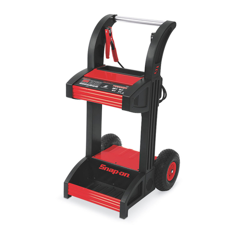
YAH166B
® 6/12/24 VOLT BATTERY CHARGER
OPERATOR'S MANUAL
WARNING
Batteries produce explosive gases and can explode.
Wear safety goggles. (User and bystanders)
Keep flames and sparks away from batteries.
Read and follow instructions.
Battery explosion and ignited gases can cause injury.
WARNING
Battery acid can cause chemical burns.
Wear protective clothing. (User and bystanders)
Chemical burns can cause injury.
IMPORTANT SAFETY INSTRUCTIONS
SAVE THESE INSTRUCTIONS: This manual contains important safety and operating instructions for the battery charger you have purchased.
You may need to refer to these instructions at a later date.
CAUTION: To reduce the risk of injury, charge only lead acid type rechargeable batteries (Lead accumulator battery). Other types of batteries may
burst, causing personal injury and property damage.
WARNING-RISK OF EXPLOSIVE GASES
WORKING IN THE VICINITY OF A LEAD-ACID OR OTHER AUTOMOTIVE BATTERY IS DANGEROUS. BATTERIES GENERATE EXPLOSIVE
GASES DURING NORMAL BATTERY OPERATION. FOR THIS REASON, IT IS OF UTMOST IMPORTANCE THAT EACH TIME BEFORE USING
YOUR CHARGER, YOU READ THIS MANUAL AND FOLLOW THE INSTRUCTIONS EXACTLY.
An extension cord should not be used unless absolutely necessary. Use of an improper extension cord could result in the risk of fire and electric shock.
If an extension cord must be used, make sure:
a. That it has a protective conductor (grounded) and a minimum cross section of 1.5mm2in accordance with local electrical safety codes.
b. For industrial and agricultural usage, use only electrical extension cords approved for these operations.
1. PREPARING TO CHARGE:
a. Be sure the area around the battery is well ventilated while the battery is being charged.
b. Clean the battery terminals.
c. Add distilled water in each cell until the battery acid reaches the level specified by the battery manufacturer. The normal level is usually 1 cm
above the lead plates.
d. Determine the voltage of the battery by referring to the vehicle owner's manual and make sure that the output voltage selector switches are set
at the correct voltage. If the charger has an adjustable charge rate, charge the battery initially at the charger's lowest rate for the battery.
2. DC CONNECTION PRECAUTIONS
a. Connect and disconnect the DC output clamps only after setting the Timer switch to the "{"(OFF) position and removing the AC cord from the
electric outlet. Never allow the clamps to touch each other.
b. When attaching a clamp to a battery post, twist or rock the clamp back and forth several times to make a good connection.
3. STOP/GO LITE INSTRUCTIONS
When used properly, the STOP/GO LITE will indicate whether the clamp connections will be correct.
Connect the Positive (Red) clamp to the Positive (POS, P, +) battery post. Touch the contact button of
the Negative (Black) clamp to the other battery post. Observe the LED lights in the STOP/GO LITE.
GREEN LIGHT: The first connection is correct. Make the second clamp connection per the instructions
in section 4.
RED LIGHT: The first connection made with the Positive (RED) clamp to the battery is incorrect.
Attach the Positive (RED) clamp to the other battery post and retest.
RED AND GREEN LIGHT: The battery charger is turned on. Turn the charger "OFF" ({) and retest.
NO LIGHT: Check for a shorted or open battery. Clean corrosion from the clamp jaws and battery
posts. Retest. If still no light, use a voltmeter or other means to make certain you have property
identified the polarity of the battery posts. Then attach the clamps per the instructions, disregarding the
STOP/GO LITE.
4. FOLLOW THESE STEPS WHEN CONNECTING THE BATTERY
a. Check the polarity of the battery posts. The Positive (POS, P, +) battery post usually has a larger
diameter then the Negative (NEG, N, -) battery post.
b. Determine which post of the battery is grounded (connected to the chassis). If the negative post is grounded to the chassis (as in most
vehicles), see paragraph 4c. If the positive post is grounded to the chassis, see paragraph 4d.
c. For a Negative ground vehicle, double check the polarity of the battery terminals, refer to the STOP/GO LITE instructions. Connect the
Positive (Red) clamp from the battery charger to the Positive (POS, P, +) ungrounded post of the battery. Connect the Negative (Black) clamp
to the vehicle chassis, a heavy gauge metal part of the frame or the engine block, away from the battery. Do not connect the clamp to the
carburetor, fuel lines or sheet metal part of the frame.
d. For a Positive ground vehicle, double check the polarity of the battery terminals, refer to the STOP/GO LITE instructions. Attach the Negative
(Black) clamp to the Negative (NEG, N, -) ungrounded post of the battery. Attach the Positive (Red) clamp to the vehicle chassis, a heavy
1
gauge metal part of the frame or the engine block, away from the battery. Do not connect the clamp to the carburetor, fuel lines or sheet metal
part of the frame.
e. When disconnecting the charger, follow these precautions:
•Turn the Timer Switch to the "{" (OFF) position.
•Disconnect the AC cord.
•Remove the clamp from the vehicle chassis.
•Remove the clamp from the battery terminal.
f. See section 5, LENGTH OF CHARGE, for information on length and rate of charge.
g. A marine (boat) battery must be removed and charged on shore. To charge it on-board requires equipment specially designed for marine use.
5. LENGTH OF CHARGE
a. Use a temperature compensating hydrometer or a voltmeter to determine the State of Charge of the battery. Do not charge a battery that is
over 75% charged or if the battery is determined to be defective. Refer to the STATE OF CHARGE TABLE.
b. Determine the Battery Size (Small, Medium or Large). Refer to the BATTERY SIZE table.
c. Refer to the CHARGE RATE Vs. MINUTES CHARGE table to determine the recommended length of charge for the battery based on its size,
state of charge and the charging amperes.
d. Discontinue charging when the specific gravity of the electrolyte reaches 1.260 or above. A temperature compensating hydrometer should be
used for this reading. Discontinue charging if the battery begins to gas excessively or when the temperature of the electrolyte reaches
approximately 50° C. Do not overcharge the battery.
23.6
11.8
5.9
1.110
23.8
11.9
5.95
1.140
24.2
12.1
6.05
1.185
24.8
12.4
6.2
1.225
25%50%75% DEAD
Open Circuit Voltage 24V
Open Circuit Voltage 12V
Open Circuit Voltage 6V
Specific Gravity
STATE OF CHARGE
STATE OF CHARGE TABLE
Cold Cranking Amps
Reserve Capacity
Ampere Hours
BATTERY SIZE
60
90
350
80+
100+
400+
40
60
275
BATTERY SIZE TABLE
LARGE
MEDIUM
SMALL
BATTERY SIZE %CHARGE
0-25
303030
454550
202020
303540
55
2025
15
25
20
35
55
15
25
45
10
20
30
20
40
55
15
30
50
10
20
30
30
60
90
25
45
70
15
30
45
15
15 15 15
10
10
10 10 10
15 30 45 60 75 90
MINUTES
A
M
P
E
R
E
S
SMALL MEDIUM LARGE
CHARGE RATE Vs. MINUTES CHARGE
25-50
50-75
50-75
25-50
0-25
50-75
25-50
0-25
ASSEMBLY INSTRUCTIONS
Remove the four handle mounting screws from the back panel. Insert the handle through the two holes in the top
panel and attach the handle to the rear of the charger using the four screws. Attach the front leg to the base with
the four hex head screws provided. Attach the wheels and axle to the base. Tap one axle nut onto the axle with a
hammer, slide one wheel onto the axle and push the axle through the base. Place the second wheel onto the axle
and tap the remaining axle nut onto the axle.
USE OF THE INSTRUMENT PANEL
The TIMER has an "{" OFF position, a 0 to 90 minute TIMED CHARGE RANGE and a "I" (ON) CONTINUOUS
CHARGE position.
a. "{" (OFF) - always make sure the timer is in the "{" (OFF) position before connecting or disconnecting the
clamps from the battery. The charger will not operate with the timer in this position.
b. 0 to 90 TIMED CHARGE RANGE - The timer will automatically turn the charger off at the end of the pre-set
charging time. Turn the timer past 20 before setting the desired time.
c. "I" CONTINUOUS CHARGE - The timer will not shut the charger OFF while in this position. Extended
charging can be done if the operator is knowledgeable in determining the proper rate and length of charge and
monitors the charging process to prevent overcharging.
d. Set the CHARGE SELECTOR switches to the correct NORMAL setting: B3 for 6V, B1 for 12V or D1 for 24V.
e. Turn the timer on and read the AMPS CHARGE meter.
f. If a higher rate of charge is desired for charging the battery, set the CHARGE SELECTOR switches to the correct FAST position; B2 for 6V,
C1 for 12V or A1 for 24V.
g. Set the timer to the desired minutes charge.
DO NOT ATTEMPT TO CHARGE A BATTERY AT A VOLTAGE DIFFERENT THAN THAT OF THE BATTERY.
BOOST STARTING/ENGINE CRANKING ASSIST
•Turn off all the lights and accessories in the stalled vehicle.
•Connect the charger to the battery per the previous instructions.
•Set the CHARGE SELECTOR switches to the correct FAST position matching the vehicle’s battery voltage.
•Charge the battery on FAST for at least five minutes before attempting to start the vehicle.
•Make sure battery is accepting current before starting vehicle.
•Start the vehicle with the charger connected to the battery.
NOTE: Do not crank the engine more than 20 seconds in any five minute period; excessive cranking may overheat and damage the starter. If the
vehicle fails to start, while waiting for the starter to cool, allow the charger to continue to charge the battery.
•Turn the timer to "O" (OFF) position before disconnecting the clamps.
2
MAINTENANCE INSTRUCTIONS
Worn clamps and jaws should be replaced. Worn parts can lead to poor connections and present a safety hazard. See the parts list for part
number of jaw and clamp kits. Any maintenance or repair of this unit that involves disassembly of the cabinet should be done only by a qualified
service technician.
WIRING DIAGRAM
REPAIR PARTS LIST
PARTS NOT SHOWN
Item Description Part No. Description Part No.
1 Front Leg...................................................................605671 Handle...................................................................................605213
Front Leg YAH166B-UNK.........................................605183 Top Panel
2 Axle w/nuts................................................................610052 YAH166B/-UNK.....................................................................611090
3 Wheel w/nuts (2).......................................................610553 YAH166B-AUS/-PP...............................................................611015
Wheel w/nuts (2) YAH166B-UNK .............................610849 YAH166B-DF/-S....................................................................611092
4 Rectifier.....................................................................610850 YAH166B-GER......................................................................611094
5 Transformer...............................................................610870 Left Side Panel (facing charger)............................................611033
6 Fan Blade..................................................................610189 Capacitor Assembly...............................................................610785
7 Fan Motor..................................................................610175
8 AC Circuit Breaker ....................................................610397
9 DC Circuit Breaker....................................................610573
DC Circuit Breaker YAH166B-AUS/-PP....................610536
10 Ammeter....................................................................605204
11 Switch w/knob...........................................................610560
12 Timer w/knob.............................................................610555
13 AC Cord
YAH166B/-DF/-GER/-S.............................................610548
YAH166B-AUS..........................................................610599
YAH166B-PP ............................................................610776
YAH166B-UNK..........................................................610612
14 DC cable set w/clamps .............................................610574
15 Stop/Go Lite..............................................................604579
16 Clamps (1 pair w/jaws)..................................................6202
17 Jaw Kit (repairs 1 clamp) ..........................................610970
18 Base..........................................................................610054
19 Front Panel
YAH166B/-UNK.........................................................611089
YAH166B-AUS/-PP...................................................611088
YAH166B-DF ............................................................611091
YAH166B-GER/-S.....................................................611093
20 Back Panel................................................................610586
Back Panel YAH166B-AUS/-PP ...............................610597
21 Right Side Panel (facing charger).............................611034
3
027-0779_english_yah166b.doc illustration list YAH166B English
Fig FILE NAME DESCRIPTION
1 STOP-GO.WPG STOP GO LITE ON BATTERY-ENGLISH
2 CHRGTABL.CXD CHARGE RATE TABLE – ENGLISH LEVEL
3 27-779A. CXD ASSEMBLY DRAWING
4 A4594-1.CXD WIRING DIAGRAM-ENGLISH
5 27-705.CXD EXPLODED ASSEMBLY-PARTS LIST
PUBLISHER: DO NOT PRINT OR TRANSLATE THIS PAGE
4

Other Snap-On Batteries Charger manuals

Snap-On PRO CHARGER 250 EEBC302A User manual

Snap-On

Snap-On PRO CHARGER 250 EEBC302A User manual

Snap-On BATTERY CHARGER PLUS User manual

Snap-On

Snap-On BATTERY CHARGER PLUS User manual

Snap-On Super 550 User manual

Snap-On

Snap-On Super 550 User manual

Snap-On YA167B User manual

Snap-On

Snap-On YA167B User manual

Snap-On BATTERY CHARGER PLUS EEBC500B-INT User manual

Snap-On

Snap-On BATTERY CHARGER PLUS EEBC500B-INT User manual

Snap-On CTC772A Series User manual

Snap-On

Snap-On CTC772A Series User manual

Snap-On EEBC300A User manual

Snap-On

Snap-On EEBC300A User manual

Popular Batteries Charger manuals by other brands

ABB HT567160 Operation manual

ABB

ABB HT567160 Operation manual

EcoFlow RIVER mini user manual

EcoFlow

EcoFlow RIVER mini user manual

Webasto PosiCharge ProCore Service manual

Webasto

Webasto PosiCharge ProCore Service manual

Outback Power Systems EXTREME OBX-IC2024S-120 owner's manual

Outback Power Systems

Outback Power Systems EXTREME OBX-IC2024S-120 owner's manual

ANSMANN BC 6-12V / 6A Operation manual

ANSMANN

ANSMANN BC 6-12V / 6A Operation manual

efacec EFAPOWER EV PC G2 Installation and user manual

efacec

efacec EFAPOWER EV PC G2 Installation and user manual

Vertu AC-35V user guide

Vertu

Vertu AC-35V user guide

NOCO Genius Genius G7200 quick start

NOCO Genius

NOCO Genius Genius G7200 quick start

Mec 999999109 instruction manual

Mec

Mec 999999109 instruction manual

MSW MSW-BC-A user manual

MSW

MSW MSW-BC-A user manual

Solarc scotty Pro manual

Solarc

Solarc scotty Pro manual

ipeatech iTable 406 user manual

ipeatech

ipeatech iTable 406 user manual

IKEA LORBY manual

IKEA

IKEA LORBY manual

RadioLink CB86-PLUS user manual

RadioLink

RadioLink CB86-PLUS user manual

Anker PowerWave manual

Anker

Anker PowerWave manual

ImaxRC b8 pro instruction manual

ImaxRC

ImaxRC b8 pro instruction manual

ABB HT844413 Operation manual

ABB

ABB HT844413 Operation manual

Hama 00115496 operating instructions

Hama

Hama 00115496 operating instructions

manuals.online logo
manuals.online logoBrands
  • About & Mission
  • Contact us
  • Privacy Policy
  • Terms and Conditions

Copyright 2025 Manuals.Online. All Rights Reserved.