efacec EFAPOWER EV PC G2 User manual
EFAPOWER
EV PC G2
AC PUBLIC CHARGING STATION
Installation and User Manual

E F A P O W E R E V - PC - I N S T A L L A T I O N A N D U S E R M A N U A L
II
Copyright and trademarks
©2014 EFACEC. All rights reserved. This material is protected by the copyright laws of Portugal and other
countries. It may not be modified, reproduced or distributed without the prior, express written consent of
EFACEC. All other products or services mentioned are the trademarks, service marks, registered trademarks or
registered service marks of their respective owners.
Symbols Index
The following symbols are used in this manual to prevent accidents, which may occur as a result of incorrect
use of the charger.
Note
Read the notes carefully to ensure safe and proper use
Warning or safety observation
Read the instructions carefully to ensure safe and proper use
Risk of electric shock
Read the instructions carefully to ensure safe and proper use
Rua Eng.º Frederico Ulrich - Apartado 3078
4471-907 MOREIRA MAIA - PORTUGAL
Tel: (+351) 229403241 - Fax: (+351) 229403209
service[email protected]
www.electricmobility.efacec.com
2725 Northwoods Parkway, Ste. B
Norcross, Georgia 30071 USA
Tel: (1) 470 395-3648 -
Fax: (1) 770 446 8920
support.e[email protected]
www.electricmobility.efacec.com

E F A P O W E R E V - PC - I N S T A L L A T I O N A N D U S E R M A N U A L
III
TABLE OF CONTENTS
1GENERAL PRODUCT DESCRIPTION............................................................................... 2
2GENERAL CHARACTERISTICS ....................................................................................... 3
2.1 TECHNICAL CHARACTERISTICS .......................................................................................................... 3
2.2 STANDARDS.................................................................................................................................. 4
3PRODUCT PARTS PRESENTATION ................................................................................ 5
4IMPORTANT SAFETY INSTRUCTIONS ........................................................................... 7
5INSTALLATION INSTRUCTIONS .................................................................................... 8
5.1 ENVIRONMENTAL REQUIREMENTS .................................................................................................... 8
5.1.1 Local Conditions ................................................................................................................................................... 8
5.1.2 Site Verification and Inspection............................................................................................................................ 9
5.2 SITE PREPARATION....................................................................................................................... 10
5.2.1 Upstream Wiring Information ............................................................................................................................ 10
5.2.2 Surface Preparation............................................................................................................................................ 12
5.2.3 Resources for Installation ................................................................................................................................... 12
5.2.4 Site Verification and Inspection.......................................................................................................................... 13
5.3 HANDLING AND PLACING .............................................................................................................. 14
5.3.1 Packaging........................................................................................................................................................... 14
5.3.2 Visual Inspection................................................................................................................................................. 14
5.3.3 Handling ............................................................................................................................................................. 14
5.3.4 Assembly Instructions / Placing.......................................................................................................................... 15
6START-UP ..................................................................................................................21
6.1 VERIFICATION AND INSPECTION...................................................................................................... 21
6.2 SWITCH ON................................................................................................................................ 21
7USER MANUAL ..........................................................................................................26
7.1 OUTPUT CONNECTORS AND OUTLETS.............................................................................................. 26
7.1.1 Type 2 outlet....................................................................................................................................................... 26
7.1.2 Type 1 Connector................................................................................................................................................ 26
7.1.3 Type 2 Connector................................................................................................................................................ 27
7.1.4 Type GB Connector ............................................................................................................................................. 27
7.1.5 CE/7 Outlet ......................................................................................................................................................... 27
7.2 OPERATING INSTRUCTIONS............................................................................................................ 28
7.2.1 User Interfaces for EV-PC WITH SOCKET............................................................................................................. 29
7.2.2 User Interfaces for EV-PC WITH PLUG ................................................................................................................ 31
8MAINTENANCE MANUAL ...........................................................................................33
8.1 PREVENTIVE MAINTENANCE .......................................................................................................... 33
8.1.1 Battery Maintenance (if applicable)................................................................................................................... 34
8.2 TROUBLESHOOTING ..................................................................................................................... 34
9ATTACHMENTS..........................................................................................................37
E F A P O W E R E V - PC - I N S T A L L A T I O N A N D U S E R M A N U A L
1 | 37
The information presented in this guide is subject to change without prior notice.
The technical specifications indicated here do not constitute a contractual obligation.
No part of this document may be photocopied, reproduced or translated to other language without the written
consent from EFACEC.
In case of any doubt regarding a subject described in this manual, please contact us at:
Rua Eng.º Frederico Ulrich - Apartado 3078
4471-907 MOREIRA MAIA - PORTUGAL
Tel: (+351) 229403241 - Fax: (+351) 229403209
service[email protected]
www.electricmobility.efacec.com
2725 Northwoods Parkway, Ste. B
Norcross, Georgia 30071 USA
Tel: (1) 470 395-3648 -
Fax: (1) 770 446 8920
support.e[email protected]
www.electricmobility.efacec.com

E F A P O W E R E V - PC - I N S T A L L A T I O N A N D U S E R M A N U A L
2 | 37
1GENERAL PRODUCT DESCRIPTION
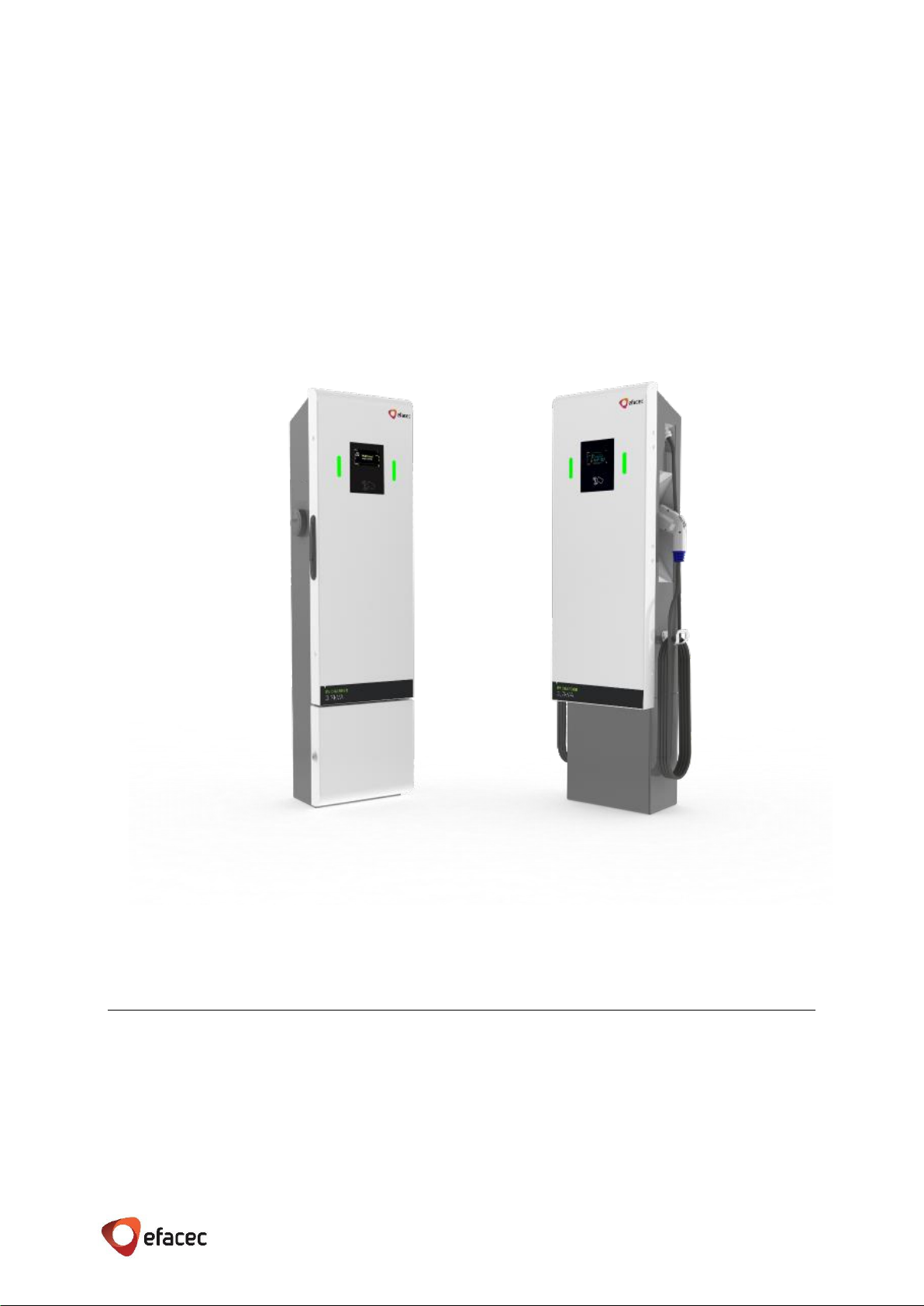
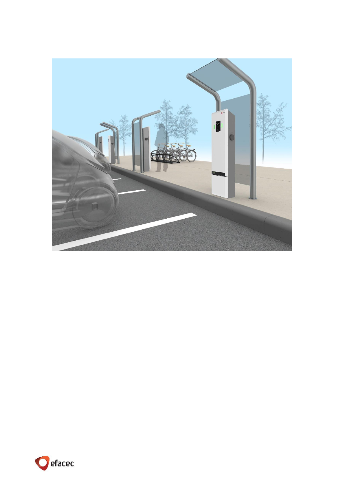
EFAPOWER EV- Public Charger station is able to charge all electric vehicles
compliant with AC charging system standards.
The charging session stop automatically based on signals from EV, or it can be
manually stopped by the user.
EFAPOWER EV-PC consists of a Charging Station with a Central Unit and up to
two outputs.
This charger is intended to be mounted on the wall (as represented in Figure
1) or anchored to the floor with an external Pedestal accessory (as
represented in Chapter 3).
The architecture of this equipment is highly scalable: one single Central Unit
is able to control the operation of several Satellite units.
The following AC outputs are available:
✓For CE marked units: 2,3kVA; 3,7kVA; 7,4kVA; 11kVA; 22kVA and 43 kVA
✓For ETL marked units: up to 7,2kVA (Level 2)
✓For GB marked units: 3,7kVA; 7,4 kVA; 11 kVA and 22kVA
EFAPOWER EV-Public Charger station is user friendly and safe. On units with a socket, there is a locking
mechanism inside the socket, which prevents the user from disconnecting the cable from the charger without
first stopping the charging process on the Central Unit. The charger has a color warning LED that shows the
operation status.
Each EFAPOWER EV-Public Charger station can be used as a stand-alone charger, or it can be integrated with a
Charging Infrastructure Network or Network Management System (NMS). The operation and status of the
individual station would then be controlled by the Central Management System.
EFAPOWER EV- PC station codification and configurations are presented in Chapter 3.
Figure 1 - EFAPOWER EV-Public Charger

E F A P O W E R E V - PC - I N S T A L L A T I O N A N D U S E R M A N U A L
3 | 37
2GENERAL CHARACTERISTICS
2.1 TECHNICAL CHARACTERISTICS
EFAPOWER EV- Public Charger station technical characteristics are indicated in Table 1.
Table 1 –EFAPOWER EV-PC Technical Characteristics
Central Unit
User Interface
User Interface
TFT
User Identification
Contactless RFID Card (Mifare) ISO14443
Communication protocol
Web services over IP
Outputs
CE Units
CE and GB Units
ETL Units
Nominal Input
Phases/Lines
1 line + neutral + earth
3 line + neutral + earth
2 lines + earth
Voltage
(230 ± 10%) Vac
(400 ± 10%) Vac
(208/240) Vac
Current
10A
16 A
32 A
16 A
32 A
63 A
30 A
Power
2,3 kVA
3,7 kVA
7,4 kVA
11 kVA
22 kVA
43 kVA
Up to 7,2 kVA
Frequency
(50 ± 10%) Hz
60 Hz
Output
Output
CE/7
CE units: Type 1 according to EN 62196-1
Type 2 according to EN 62196-2
GB units: GB/T 18487.1 Mode 3
ETL units: Type 1
according to SAE J1772
EV Connection to EVSE
CE units: EN 61851-1 and IEC 61851-1 Case B
GB units: GB/T 18487.1 Case C
SAE J1772
Outlet Protection
Over-current
12A
20 A
40 A
20 A
40 A
63 A
40 A
RCD / CCID
30 mA
20 mA
Charging Mode
Direct connection
between the EV and the
EVSE using the cable
supplied with the vehicle.
CE units: EN 61851-1 e IEC 61851-1 Mode 3
GB units: GB/T 18487.1 Mode 3
ETL units: SAE J1772 Mode 3
Energy metering
In each output
Yes
Mechanical
Characteristics
Dimensions(WxDxH) mm
Wall Mount Unit: 374x275x1080 mm
Wall Mount Unit + Pedestal: 374x275x1450 mm
14.7 x 10.8 x 42.5 inches
14.7 x 10.8 x 57.1
Architecture
Central Cabinet equipped with Central Unit and up to 2 outputs
(additional 2 x CE7 outputs as optional, only for CE units)
Satellite Cabinet equipped with Central Unit and up to 2 outputs
(additional 2 x CE7 outputs as optional, only for CE units)
Weight (depending on
output configuration)
from 20kg to 30kg
44 lb to 66 lb
Environmental
conditions
Degree of protection
IP54
NEMA 3R
Temperature
-30˚C to +50˚C
-22˚F to +122˚F
Humidity
Range 5% to 95%
Installation site
Outdoor/Indoor
Specifications are subject to change, without prior notice.

E F A P O W E R E V - PC - I N S T A L L A T I O N A N D U S E R M A N U A L
4 | 37
2.2 STANDARDS
The EFAPOWER EV-Public Charger station complies with the following standards:
Table 2 –EFAPOWER EV-PC Applicable Standards
1
2014/35/UE: Low Voltage Directive
2
2014/30/UE: EMC directive
3
EN/IEC 61851-1: Electric vehicle conductive charging system. Part 1: General Requirements
4
IEC 62196: Plugs, socket-outlets, vehicle connectors and vehicle inlets - Conductive charging of electric vehicles
5
UL 2231-1: Personnel Protection Systems for Electric Vehicle (EV) Supply Circuits: General Requirements
6
UL 2231-2: Personnel Protection Systems for Electric Vehicle (EV) Supply Circuits: Particular Requirements for
Protection devices for Use in Charging Systems
7
UL 2202: Electric Vehicle (EV) Charging System Equipment
8
UL 2594: Standard for Safety of Electric Vehicle Supply Equipment
9
SAEJ1772: SAE Surface Vehicle Recommended Practice J1772, SAE Electric Vehicle Conductive Charge Coupler
10
ADA: American with Disabilities Act
11
GB 156-2007: Standard Voltage
12
GB/T 18487.1: Electric Vehicle Conductive Charging System. Part 1: General Requirements
13
GB/T 20234: Connection Set of Conductive Charging for Electric Vehicles
14
GB/T 18487.3: Electric Vehicle Conductive Charging System. AC/DC Electric Vehicle Charging Station
15
EN/IEC 61851-22: Electric vehicle conductive charging system. Part 22: AC Electric Vehicle Charging Station
16
EN/IEC 61000-6-1: Electromagnetic compatibility (EMC). Part 6-1: Generic standards - Immunity for residential,
commercial and light-industrial environments
17
EN/IEC 61000-6-3: Electromagnetic compatibility (EMC). Part 6-3: Generic standards - Emission standard for
residential, commercial and light-industrial environments
18
GB/T 17626: Electromagnetic Compatibility –Immunity to Disturbance (GB/T 17626.2; GB/T 17626.3; GB/T
17626.4; GB/T 17626.5; GB/T 17626.6; GB/T 17626.11)
19
GB 4824: Industrial, scientific and medical (ISM) radio-frequency equipment. Disturbance characteristics.
Limits and methods of measurement.
Technical Data
CE
ETL
GB
Applicable
Standards
Universal:
2014/35/UE1
2014/30/UE2
EN/IEC 61851-13
IEC 621964
UL 2231-15
UL 2231-26
UL 22027
UL 25948
SAE J17729
ADA10
GB 156-200711
GB/T 18487.112
GB/T 2023413
GB/T 18487.314
AC Charging System:
EN/IEC 61851-2215
EN/IEC 61000-6-116
EN/IEC 61000-6-317
EV-READY
--
GB/T 1762618
GB 482419
EV-READY
E F A P O W E R E V - PC - I N S T A L L A T I O N A N D U S E R M A N U A L
5 | 37
3PRODUCT PARTS PRESENTATION
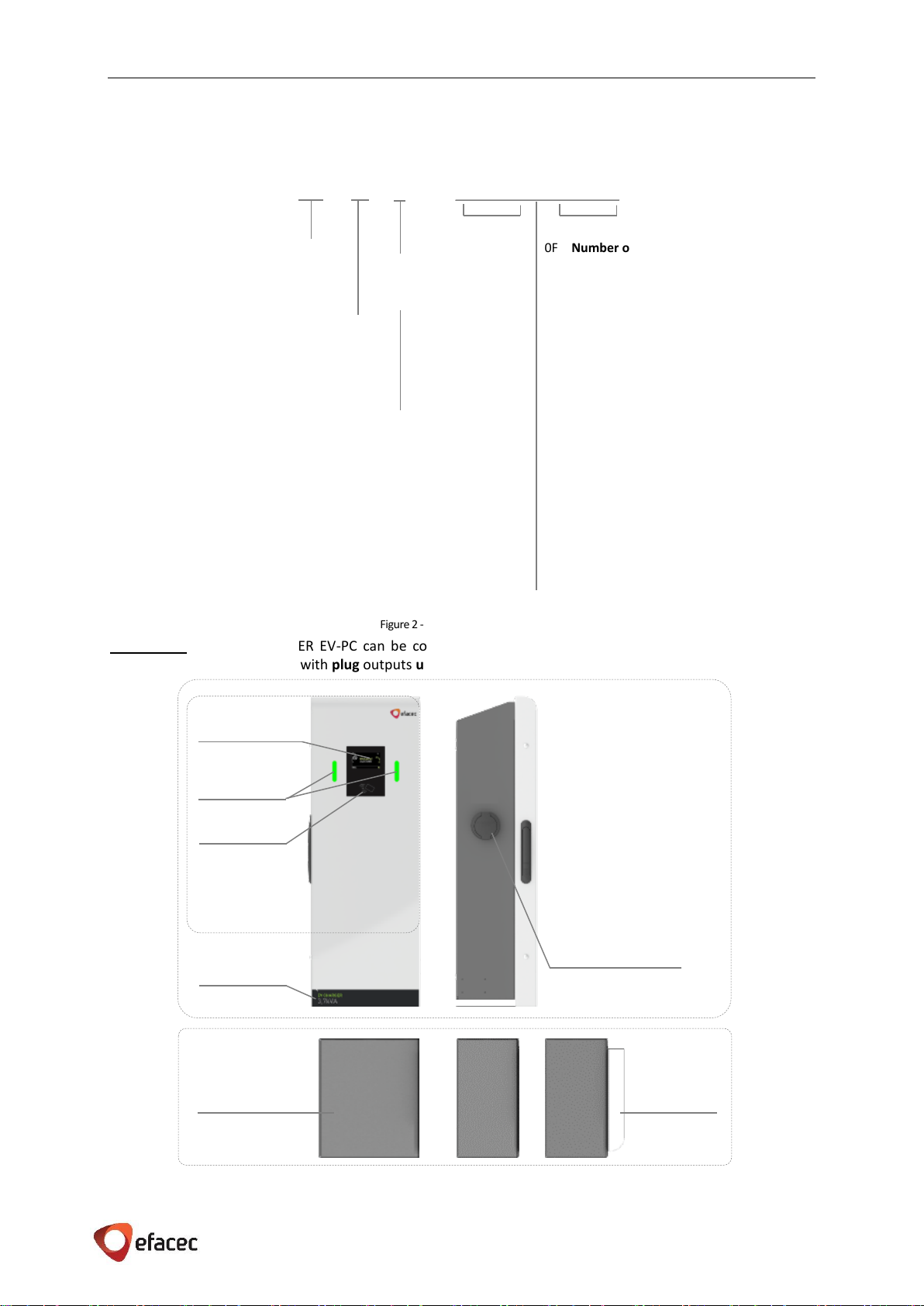
EFAPOWER EV-PC is composed by an Unit with outputs. Its codification is presented below.
CE marked units of EFAPOWER EV-PC can be configured with socket outputs from 3,7kVA up to 22kVA (+
optional 2 Schuko outputs) or with plug outputs up to 43kVA (+ optional 2 Schuko outputs).
Figure 3 - EFAPOWER EV-PC Socket Station Parts
EV-XX G2 CE XCCX 0F00GKK 0F00GKK
Central Wall mount
CW
Satellite Wall mount
SW
Communications
X
GSM
G
CDMA
C
Figure 2 - EFAPOWER EV-PC Codes
0F
Number of Phases
1F
One-phase
3F
Three-phase
13F
2 Outputs: 1F + 3F
00
Current
10
10 A
16
16 A
30
30 A
32
32 A
63
63 A
10+16
2 Outputs: 10 A + 16 A
10+32
2 Outputs: 10 A + 32 A
G
Plug/Socket
P
Plug
S
Socket
KK
Mode
CE7
CE/7
T1
Type T1
T2
Type T2
CE7T2
2 Outputs: CE/7 + Type 2
1st Output
2nd Output
CE European markets
UL USA & Canada markets
GB China market
Optional
Pedestal
Optional
Pedestal with
door
Fixing to the floor
Mount
RFID
TFT color
Output connection
Output
signaling
Wall Mount
Central Unit
Power rating
indication
E F A P O W E R E V - PC - I N S T A L L A T I O N A N D U S E R M A N U A L
6 | 37
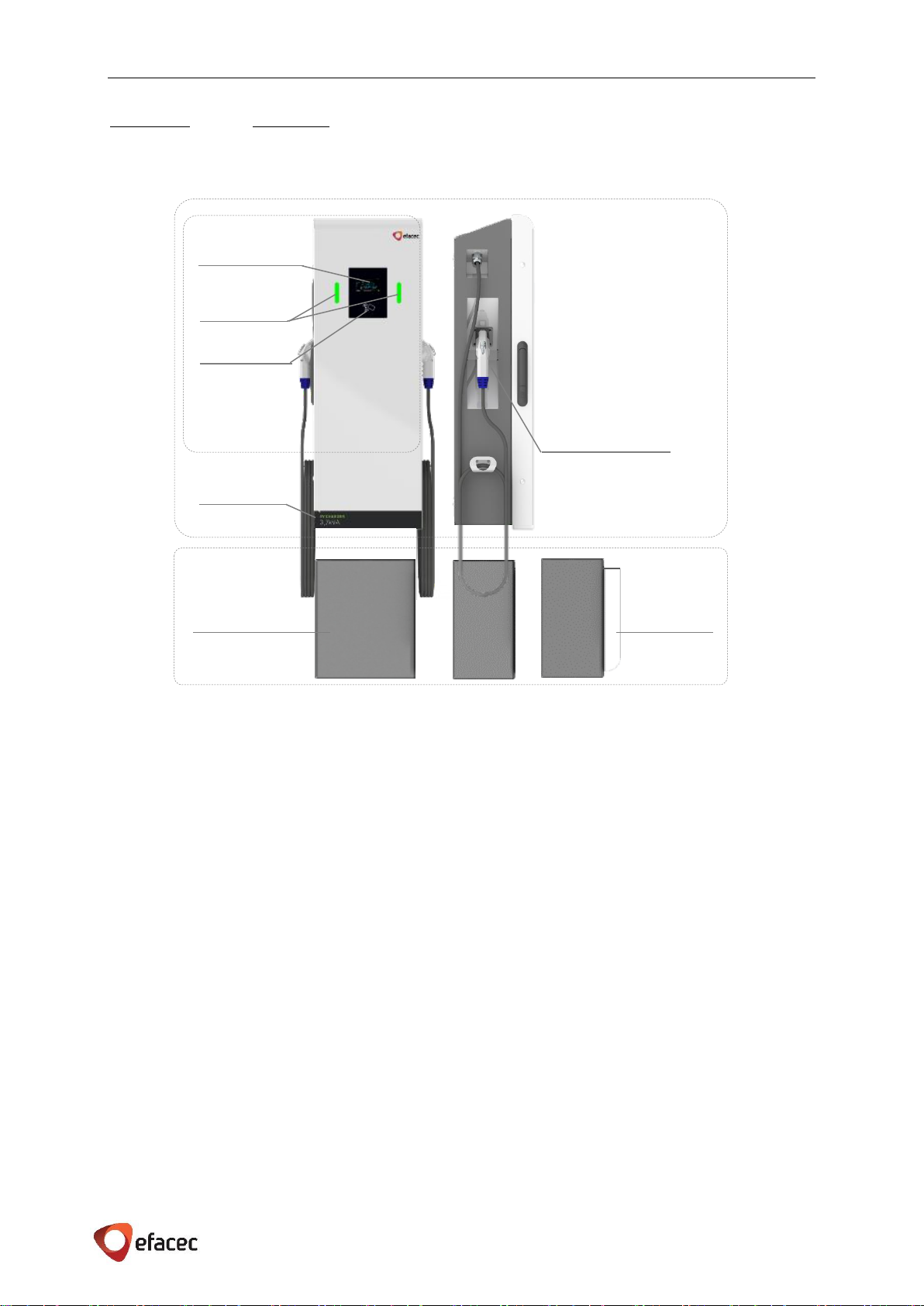
ETL marked units and GB marked units have the same appearance but with a difference on the output power
rating:
EFAPOWER EV-PC for USA market (aka Level 2) has 2 plug outputs of up to 7,2kVA.
EFAPOWER EV-PC for China market can be configured with 2 plug outputs from 3,7kVA up to 22kVA.
Figure 4 - EFAPOWER EV-PC Plug Station Parts
Output connection
Wall Mount
Central Unit
Optional
Pedestal
Optional
Pedestal with
door
Fixing to the floor
Mount
Power rating
indication
TFT color
Output
signaling
RFID

E F A P O W E R E V - PC - I N S T A L L A T I O N A N D U S E R M A N U A L
7 | 37
4IMPORTANT SAFETY INSTRUCTIONS
SAVE THESE INSTRUCTIONS
This manual contains important instructions that must be followed during installation, operation and
maintenance of the unit EFAPOWER EV-PC Station, which include the models according to chapter 3 codification.
WARNING - When using electric products basic precautions should always be followed:
a) Read all the instructions before using this product.
b) This device should be supervised when used around children.
c) Do not put fingers into the electric vehicle connector.
d) Do not use this product if the flexible power cord or EV cable is frayed, has broken insulation, or any other
signs of damage.
e) Do not use this product if the enclosure or the EV connector is broken, cracked, open, or shows any other
indication of damage.
Grounding instructions
The EFAPOWER EV-PC Station must be connected to a grounded, metal, permanent wiring system; or an
equipment-grounding conductor is to be run with circuit conductors and connected to the equipment grounding
terminal or lead on the Electric Vehicle Supply Equipment (EVSE). Connections to the EVSE shall comply with all
local codes and ordinances, and should follow the NEC (National Electrical Code) or the CEC (Canadian Electrical
Codes) accordingly.
WARNING –Improper connection of the equipment-grounding conductor is able to result in a risk of
electric shock. Check with a qualified electrician or serviceman if you are in doubt as to whether the
product is properly grounded. Do not modify the plug provided with the product –if it will not fit the outlet,
have a proper outlet installed by a qualified electrician.
Safety and compliance
This document provides instructions to install the EFAPOWER EV-PC Station and should not be used for any other
product. Before installing the EFAPOWER EV-PC Station, you should review this manual carefully and consult with
a licensed contractor, licensed electrician and trained installation expert to ensure compliance with local building
practices, climate conditions, safety standards, state and local codes, and should follow the NEC (National
Electrical Code) or the CEC (Canadian Electrical Codes) accordingly. The EFAPOWER EV-PC Station should be
installed only by a licensed contractor and a licensed electrician and in accordance with all local and national
codes and standards. The EFAPOWER EV-PC Station should be inspected by a qualified installer prior to the initial
use. Under no circumstances will compliance with the information in this manual relieve the user of his/her
responsibility to comply with all applicable codes or safety standards. This document describes the most
commonly-used installation and mounting scenarios. If situations arise in which it is not possible to perform an
installation following the procedures provided in this document, contact EFACEC. EFACEC is not responsible for
any damages that may occur resulting from custom installations that are not described in this document.
No accuracy guarantee
Reasonable effort was made to ensure that the specifications and other information in this manual are accurate
and complete at the time of its publication. However, the specifications and other information in this manual are
subject to change at any time without prior notice.
Warranty information and disclaimer
Your use of, or modification to, the EFAPOWER EV-PC Station in a manner in which the EFAPOWER EV-PC Station
is not intended to be used or modified will void the limited warranty. Other than any such limited warranty, the
EFACEC products are provided “AS IS,” and EFACEC and its distributors expressly disclaim all implied warranties,
including any warranty of design, merchantability, fitness for a particular purposes and non-infringement, to the
maximum extent permitted by law.
Limitation of liability
IN NO EVENT SHALL EFACEC OR ITS AUTHORIZED DISTRIBUTORS BE LIABLE FOR ANY INDIRECT, INCIDENTAL,
SPECIAL, PUNITIVE, OR CONSEQUENTIAL DAMAGES, INCLUDING WITHOUT LIMITATION, LOST PROFITS, LOST
DATA, LOSS OF USE, COST OF COVER, OR LOSS OR DAMAGE TO THE EFAPOWER EV-PC STATION, ARISING OUT
OF OR RELATING TO THE USE OR INABILITY TO USE THIS MANUAL, EVEN IF EFACEC OR ITS AUTHORIZED
DISTRIBUTORS HAVE BEEN ADVISED OF THE POSSIBILITY OF SUCH DAMAGES.

E F A P O W E R E V - PC - I N S T A L L A T I O N A N D U S E R M A N U A L
8 | 37
5INSTALLATION INSTRUCTIONS
5.1 ENVIRONMENTAL REQUIREMENTS
EFAPOWER EV-PC Station reliability is dependent upon compliance of environmental specifications. The design
of the environmental control system for your EFAPOWER EV-PC Station, in case of extreme environmental
conditions, must ensure that the Unit can operate reliably while remaining within the range of its operating
specifications.
The enclosure should be inspected during maintenance for evidence of damage or deterioration. A soft cloth
moistened with water must be used to remove accumulated dust and dirt on the outside of the unit to preserve
the integrity of the structure and avoid displacing dust or dirt into any delicate components of the equipment.
Seals and gaskets should be examined and repaired or replaced if required and fasteners tighten should be
verified. The frequency of maintenance of the enclosure should be increased with extreme weather conditions.
5.1.1 LOCAL CONDITIONS
EFAPOWER EV-PC Station is an IP54 (NEMA 3R) enclosure. This Unit is intended to work below 50ᵒC (122°F)
ambient temperature.
Clearance around the cabinet
We advise to have at least 0,5 m (20”) in the front and both sides, or according to local codes
Input Power Cables
AC input cables must be copper with appropriate power rating.
Distance between Units
Whenever it’s required the installation of Central and Satellite Units, the Ethernet cable connecting the units
shall not be longer than 100 meters.
EFAPOWER EV-PC Station can be placed as showed in Figure 5.
Figure 5 - EFAPOWEREV-PC Station - placing
E F A P O W E R E V - PC - I N S T A L L A T I O N A N D U S E R M A N U A L
9 | 37
On locations with extreme weather conditions (harsh temperatures or snow) it’s recommended to provide additional
protection, either inside a building or a shelter, or providing a roof protection for the Unit. See example in Figure 6.
Figure 6 - EFAPOWER EV-PC Station with roof protection
5.1.2 SITE VERIFICATION AND INSPECTION
✓Check if the access passages to the Public Charger Station layout site are not blocked in order to allow its
transportation;
✓Check if the Public Charger Station layout site is compliant with the specified clearance around the cabinet;
✓In case of installation of Central and Satellite Units, make sure that the distance between units will comply
with cable length requirement (no longer than 100 meters).

E F A P O W E R E V - PC - I N S T A L L A T I O N A N D U S E R M A N U A L
10 | 37
5.2 SITE PREPARATION
Once the local conditions have been verified, it is time to prepare the site for the installation of the EFAPOWER
EV- PC Station.
5.2.1 UPSTREAM WIRING INFORMATION
Depending on the configuration of the EFAPOWER EV-PC, the station may have different wiring schemes as
represented in the following three figures.
CE AND GB MARKED UNITS:
•Three phase input connection for CE and GB marked units:
.
Figure 7 - EFAPOWER EV-PC CE/GB Wiring Information (Three-Phase)
Depending on the configuration of the outputs (of
the units) we can have several scenarios for the
circuit breaker to be installed in the distribution
board for each Unit. The appropriate circuit
breaker is represented in Table 3.
Efacec advises a Residual Current Device (RCD)
2P/4P Type AC or 2P/4P Type A, higher than
300mA, to ensure the upstream selectivity. All
local codes shall be taken into consideration.
NOTES
Even if the same Unit side has two outputs
(2,3kVA + any other power rate) the Table 3 is
valid because only one output will work at a time.
In areas with frequent thunderstorms, we advise
to add transient voltage surge suppression (TVSS)
at the service panel for all circuits.
1st Output
2nd Output
---
16A
3P C
20A
3P C
40A
3P C
80A
3P C
63A
3P C
100A
3P C
20A 3P C
40A 3P C
63A
3P C
80A
3P C
125A
3P C
63A
3P C
40A
3P C
63A
3P C
100A
3P C
63A 3P C
80A
3P C
63A
3P C
80A
3P C
125A
3P C
100A 3P C
125A
3P C
100A
3P C
125A
3P C
160A
3P C
Table 3 - Overcurrent protection upstream
* Only available for CE marked units
*
*
*
*

E F A P O W E R E V - PC - I N S T A L L A T I O N A N D U S E R M A N U A L
11 | 37
ETL MARKED UNITS:
•Single phase input connection for ETL marked units (two hot wires per output):
Figure 8 - EFAPOWER EV-PC UL Wiring Information (Two Hot Wires Per Output)
This Unit has only one power output rate available. This installation requires a dedicated 40A circuit
breaker 2P C curve per output.
•Single phase input connection for ETL marked units (two hot wires shared by both outputs):
For the power sharing feature, shall be placed three shunts (Weidmuller - 1053260000) across phases
and ground terminal blocks, represented in orange (X1.1 and X1.2; X1.3 and X1.4; X1.5 and X1.6).
Figure 9 - EFAPOWER EV-PC UL Wiring Information (Two Hot Wires Share by Two Outputs)
This Unit has only one power output rate available. This installation requires only one dedicated 40A
circuit breaker 2P C curve.
NOTES
In areas with frequent thunderstorms, we advise to add transient voltage surge suppression (TVSS)
at the service panel for all circuits.
A Residual Current Device is not necessary for the circuit breaker, unless it is required by local codes.
EFAPOWER EV-PC Station has already ground fault protection.

E F A P O W E R E V - PC - I N S T A L L A T I O N A N D U S E R M A N U A L
12 | 37
5.2.2 SURFACE PREPARATION
Each Charging Station can be mounted to the floor, or to the pavement by a proper base, or on the wall
depending on the product configuration. Check local codes to ensure compliance.
The Charging Station shall be mounted at a sufficient height from grade, such that the height of the storage
means for the coupling device, is located between 600 mm (24 inches) and 1.2 m (4 feet) from grade.
5.2.3 RESOURCES FOR INSTALLATION
For the installation of EFAPOWER EV-PC Station, the following items will be needed:
Fasteners:
Mounting on the Wall
▪Concrete wall: 4 (four) anchors, M5 –length must comply with local codes –with matching nuts and washers,
or
▪Drywall: 2 (two) anchors (13/64’’ dia. (M5) lag screws ) in studs and 2 (two) drywall anchors heavy-duty
Anchoring to the Floor
▪4 (four) screws M8, with matching nuts and washers
End terminals for input wiring by Unit:
▪CE or GB marked units:5 (five) end terminals for cable according to Table 5 or according to local codes
(3phases + neutral + protective ground)
Table 4 –Max current by phase
1st Output
---
16A
16A
32A
48A
80A
32A
48A
64A
95A
48A
32A
48A
80A
48A
64A
48A
64A
95A
80A
95A
80A
95A
126A
Table 5 - Input lines –cross-section range
*These cross-sections are applied to cooper cable length up
to 50m. For longer distances, contact the manufacturer.
max A
Min cross-section*
Terminal block section
16 A
2,5mm2
6mm2
32 A
4mm2
6mm2
48 A
6mm2
16mm2
64 A
10mm2
16mm2
80 A
25 mm2
35 mm2
95 A
25 mm2
35 mm2
126 A
35 mm2
50 mm2
▪ETL marked units: 6 (six) end terminals for cable up to 4 AWG or according to local codes (4 hot wires + 2
protective ground)
2nd Output

E F A P O W E R E V - PC - I N S T A L L A T I O N A N D U S E R M A N U A L
13 | 37
Connection between Central and Satellite Units –only communications (if applicable):
▪Ethernet patch cable STP CAT5e TIA/EIA-568B
Tools:
▪Screwdriver - for fixing the Unit on the wall
▪13mm socket and wrench - for fixing the Unit to the floor
▪Crimping tool - for power and earth cables
▪Torque screwdriver with flat blade - for input terminal blocks
5.2.4 SITE VERIFICATION AND INSPECTION
✓Check if Public Charger has the appropriate upstream protection depending on the configuration.
✓Check if the surface where the Public Charging Station will be placed is leveled as specified.
E F A P O W E R E V - PC - I N S T A L L A T I O N A N D U S E R M A N U A L
14 | 37
5.3 HANDLING AND PLACING
Before installing stations
The instructions provided in this manual assume that the appropriate wiring, circuit protection, and
metering are in place at the installation location.
To assist in the process of preparing the installation site, it is recommended that before you begin
installing Charging Station, you thoroughly review the contents of this document to familiarize
yourself with the required installation steps.
Les instructions fournies dans ce guide présume que le câblage approprié, la protection du circuit et
l’outillage de mesure sont en place à l'emplacement d'installation.
Pour aider dans la procédure de préparation du local d'installation, il est recommandé qu’avant de
démarrer l'installation de la station de recharge, vous examinez soigneusement le contenu de ce
document pour vous familiariser avec les étapes d'installation nécessaires.
In case of any doubt regarding items described in this guide, please contact us at:
5.3.1 PACKAGING
EFAPOWER EV-PC Station is shipped in a package that, depending on the order, can be packaged in a group (Central
Unit + Satellite Units). The dimension of each Unit is in Chapter 2.1 - Technical characteristics.
5.3.2 VISUAL INSPECTION
✓Check if the exterior case has been damaged by mechanical impacts or any accidents during transportation
✓If applicable, check if the EFAPOWER EV-PC Station decor is in perfect condition
✓Check if the interior of the Unit(s) is/are clean
✓Check if the doorsof the Unit(s) are working properly
✓Check for proper Unit(s) protective ground connection point, which should be interconnected with the low
voltage switchboard ground connection during the installation
5.3.3 HANDLING
Each EFAPOWER EV-PC Unit is fixed to a pallet and should be transported with a pallet jack or similar as close as
possible to the installation site.
Due to its weight (max 30kg), this Charging Station can be placed by two persons.
Rua Eng.º Frederico Ulrich - Apartado 3078
4471-907 MOREIRA MAIA - PORTUGAL
Tel: (+351) 229403241 - Fax: (+351) 229403209
service[email protected]
www.electricmobility.efacec.com
2725 Northwoods Parkway, Ste. B
Norcross, Georgia 30071 USA
Tel: (1) 470 395-3648 -
Fax: (1) 770 446 8920
support.e[email protected]
www.electricmobility.efacec.com

E F A P O W E R E V - PC - I N S T A L L A T I O N A N D U S E R M A N U A L
15 | 37
5.3.4 ASSEMBLY INSTRUCTIONS / PLACING
This Unit was designed to be mounted on the wall. Nevertheless, with an external accessory can also be
anchored to the floor. The next chapters have the necessary information for both situations.
5.3.4.1 MOUNTING ON THE WALL
The EV-CW and EV-SW are prepared to be mounted on the wall.
In the following figures some details are shown regarding the drilling layout for the Unit.
Each unit must be installed by using 4 (four) M5 bolts. Length must comply with local codes. While a concrete
wall for installation is preferred, installation on a drywall will be acceptable if at least 2 anchors (13/64’’ dia. (M5)
lag screws) are in studs and if the remaining drywall anchors are heavy-duty.
Depending on the configuration of the EFAPOWER EV-PC, we have different cable entry points, which are
represented in the following two figures. The cable entry shall respect the place that was assigned to it (market
with green).
CE and GB MARKED UNITS:
▪Cable gland M40: AC input (refer Chapters 5.3.4.3 and 5.3.4.4)
▪Cable gland M25 (for connections between central and satellite units): communication cable (refer to
Chapter 5.3.4.5)
Figure 10 - EFAPOWER EV-PC CE / GB Drilling and conduits Layout (rear view)

E F A P O W E R E V - PC - I N S T A L L A T I O N A N D U S E R M A N U A L
16 | 37
ETL MARKED UNITS:
▪Two cable glands M32: one for each AC input (refer to Chapters 5.3.4.3 and 5.3.4.4)
▪Cable gland M25 (for connections between central and satellite units): communication cable (refer to
Chapter 5.3.4.5)
Figure 11 - EFAPOWER EV-PC UL Drilling and conduits Layout

E F A P O W E R E V - PC - I N S T A L L A T I O N A N D U S E R M A N U A L
17 | 37
5.3.4.2 ANCHORING TO THE FLOOR
The EFAPOWER EV-PC is prepared to be fixed to the floor, however, to do so it’s required the use of a Pedestal
or Pedestal with door.
Each unit must be installed by using 4 (four) anchors, M8 –length must comply with local codes.
In the following figures some details are shown regarding the drilling layout for the Unit.
Only 4(four) points are needed to mount each Unit on the floor (marked with a red circle).
Depending on the configuration of the EFAPOWER EV-PC, we have different cable entry points, which are
represented in the following two figures. The cable entry shall respect the place that was assigned to it (market
with green).
CE and GB MARKED UNITS:
▪Cable gland M40: AC input (refer to Chapters 5.3.4.3 and 5.3.4.4)
▪Cable gland M25 (for connections between central and satellite units): communication cable (refer to
Chapter 5.3.4.5)
Figure 12 - EFAPOWER EV-PC CE / GBwith pedestal Drilling and conduits Layout
(bottom view)
Front Side
Table of contents
Other efacec Batteries Charger manuals


