manuals.online logo
Brands
  1. Home
  2. •
  3. Brands
  4. •
  5. Snapper
  6. •
  7. Lawn And Garden Equipment
  8. •
  9. Snapper 1691765 User manual

Snapper 1691765 User manual

Other Snapper Lawn And Garden Equipment manuals
Snapper 1691852 User manual

Snapper

Snapper 1691852 User manual

Snapper TA 520 Operation and maintenance manual

Snapper

Snapper TA 520 Operation and maintenance manual

Snapper 1690729 User manual

Snapper

Snapper 1690729 User manual

Snapper 82597 Installation instructions

Snapper

Snapper 82597 Installation instructions

Snapper FM7300 Operation and maintenance manual

Snapper

Snapper FM7300 Operation and maintenance manual

Snapper SCRAMBLERS Manual

Snapper

Snapper SCRAMBLERS Manual

Snapper 80575 User manual

Snapper

Snapper 80575 User manual

Snapper 1690680 User manual

Snapper

Snapper 1690680 User manual
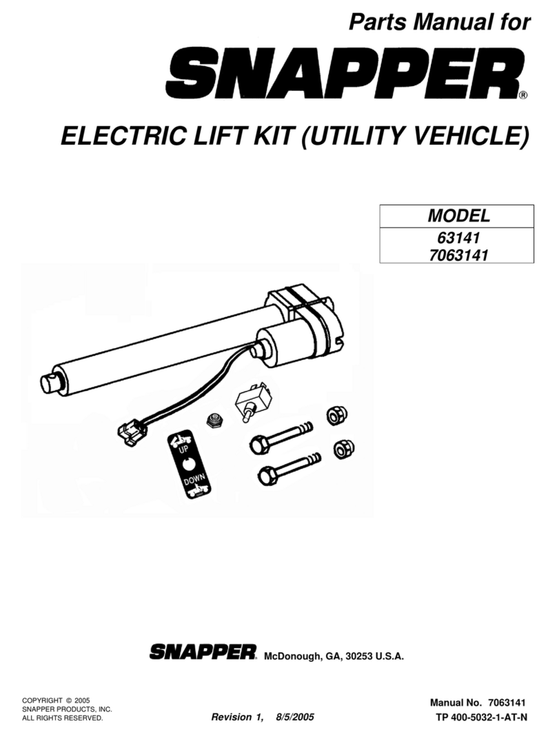
Snapper 63141 User manual

Snapper

Snapper 63141 User manual

Snapper Clean Sweep Triple Catcher User manual

Snapper

Snapper Clean Sweep Triple Catcher User manual

Snapper 1691531 User manual

Snapper

Snapper 1691531 User manual

Snapper 21SST User manual

Snapper

Snapper 21SST User manual

Snapper 6-1014 User manual

Snapper

Snapper 6-1014 User manual

Snapper 6-0990 Guide

Snapper

Snapper 6-0990 Guide

Snapper 1691351 User manual

Snapper

Snapper 1691351 User manual

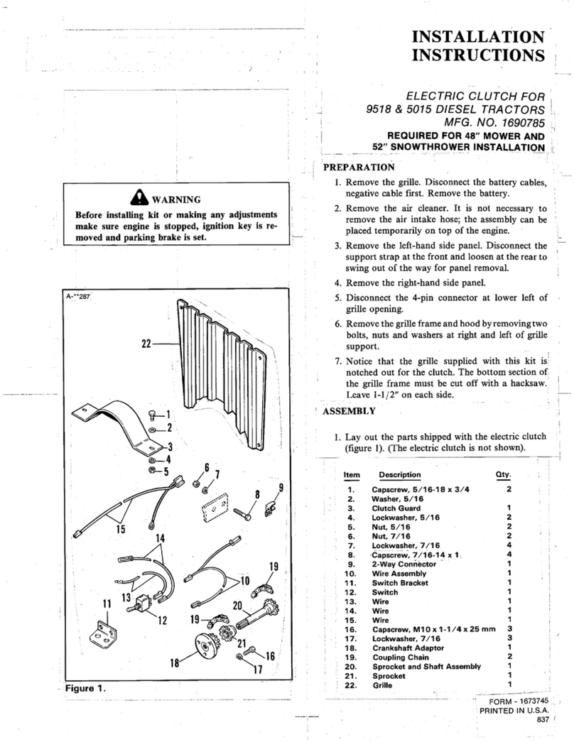
Snapper 1690785 User manual

Snapper

Snapper 1690785 User manual

Snapper 6-0730 User manual

Snapper

Snapper 6-0730 User manual

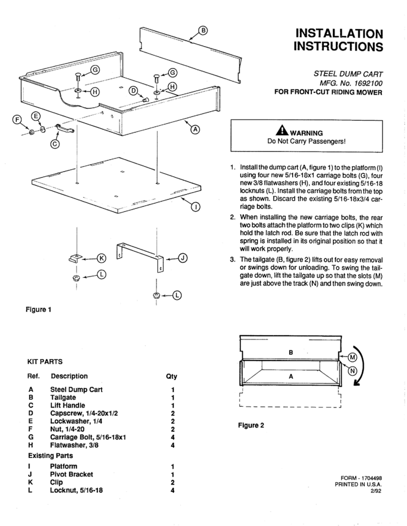
Snapper 1692100 User manual

Snapper

Snapper 1692100 User manual

Snapper 1692376 User manual

Snapper

Snapper 1692376 User manual

Snapper 1690809 User manual

Snapper

Snapper 1690809 User manual

Snapper 1690624 User manual

Snapper

Snapper 1690624 User manual

Snapper 1690681 User manual

Snapper

Snapper 1690681 User manual
Snapper 1690772 User manual

Snapper

Snapper 1690772 User manual

Snapper 6-1811 User manual

Snapper

Snapper 6-1811 User manual
Popular Lawn And Garden Equipment manuals by other brands

Sunforce SOLAR user manual

Sunforce

Sunforce SOLAR user manual

GARDEN OF EDEN 55627 user manual

GARDEN OF EDEN

GARDEN OF EDEN 55627 user manual

Goizper Group MATABI POLMINOR instruction manual

Goizper Group

Goizper Group MATABI POLMINOR instruction manual

Rain Bird 11000 Series Operation & maintenance manual

Rain Bird

Rain Bird 11000 Series Operation & maintenance manual

Cub Cadet BB 230 brochure

Cub Cadet

Cub Cadet BB 230 brochure

EXTOL PREMIUM 8891590 Translation of the original user manual

EXTOL PREMIUM

EXTOL PREMIUM 8891590 Translation of the original user manual

Exmark SAR481KA30 Operator's manual

Exmark

Exmark SAR481KA30 Operator's manual

Yazoo/Kees Z12 Operator's manual

Yazoo/Kees

Yazoo/Kees Z12 Operator's manual

Makita EM408MP Original instruction manual

Makita

Makita EM408MP Original instruction manual

Exmark Quest Bagger Setup instructions

Exmark

Exmark Quest Bagger Setup instructions

Manitou Systems AS960 Operator's manual

Manitou Systems

Manitou Systems AS960 Operator's manual

Vertex 1/3 HP Maintenance instructions

Vertex

Vertex 1/3 HP Maintenance instructions

GHE AeroFlo 80 manual

GHE

GHE AeroFlo 80 manual

Land Pride Post Hole Diggers HD25 Operator's manual

Land Pride

Land Pride Post Hole Diggers HD25 Operator's manual

Yazoo/Kees Z9 Commercial Collection System Z9A Operator's & parts manual

Yazoo/Kees

Yazoo/Kees Z9 Commercial Collection System Z9A Operator's & parts manual

Premier designs WindGarden 26829 Assembly instructions

Premier designs

Premier designs WindGarden 26829 Assembly instructions

Mosquito Magnet Patriot Operation manual

Mosquito Magnet

Mosquito Magnet Patriot Operation manual

Perfect BG2 owner's manual

Perfect

Perfect BG2 owner's manual

manuals.online logo
manuals.online logoBrands
  • About & Mission
  • Contact us
  • Privacy Policy
  • Terms and Conditions

Copyright 2025 Manuals.Online. All Rights Reserved.

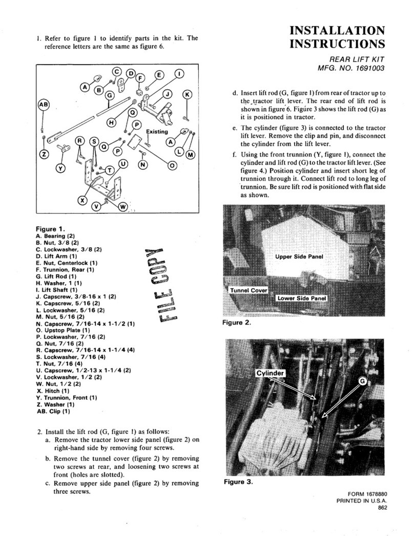
KIT PARTS
Figure 1. Kit Parts
Ref. Description
A. Searing
8.
Nut.
3/a
C. Lockwasher.
3/E
D. Lift Arm
E.
Nut,
Centerlock
F.
Trunnion, Rear
0.
Lift Rod
H. Washer, 1
I.
Lift Shaft
J. Capscrew,
3/S-16
x
1
K.
Capscrew,
6/16
1.
Lockwasher,
5/l
6
PA.
Nut,
5/16
N. Caoscrew. 7/18-14x
l-1/2
0. upstop
Plate
P.
Lockwasher,
7/16
QW
2
2
2
1
1
1
1
1
1
2
2
2
2
1
1
2
Cl. Nut,
7/16
2
R.
Capscrew,
7/16-14x
l-l/4
4
S.
Lockwasher.
7/18
4
T.
Nut.
7/16
4
U.
Capscrew,
1/2-13x
l-1/4
2
V.
Lockwasher.
l/2
2
W. Nut,
l/2
2
X.
Hitch
1
Y.
Trunnion, Front
1
2.
Washer
1
AA. Clip
~~~
~~~~~ 1
88.
Capscrew,
7/16x
l-1/4
1
CC. Washer, Special
1
INSTALLATION
1.
Install the
lit
rod (G, figure 1 ) as follows:
a. Open tractor hood. 1
b. Remove the tractor lower side
panel(A,
figure 2) on
!
right-hand side by removing four screws.
INSTALLATION
INSTRUCTIONS,’
REAR
LlFT
KIT
MFG. NO. 1691765
c. Remove the tunnel cover (B) by removing
two
screws
at rear and loosening left front screw.
d. Remove upper side panel (C) by removing three
screws. Retain the hood catch for reassembly.
Figure 2.
A. Lower Side Panel
8. Tunnel Cover
C. Upper Side Panel
e.
Insert lift rod (G, figure 1) from rear of tractor up to
the tractor lift lever. The rear end of lift rod is
shown in figure 8. Figure 3 shows the
lit
rod as it is
positioned in tractor.
f. The cylinder (figure 3) is connected to the tractor
lift lever. Remove the clip and pin, and disconnect
the cvlinder from the lift lever.
Figure 3.
FORM
-
1702006
PR,NTED IN U.S.A.
..-
,I/88
1
g. Using the front trunnion
(Y;
figure I), connect the
cylinder and lift rod(G) to the tractor lift lever. (See
figure
4.) Position cylinder and insert short leg of
trunnion through it. Connect lift rod to long leg of
trunnion. Be sure lift rod is positioned with flat side
as shown.
VIEWED FROM TOP
~FRONT
-
Figure 4.
2. For 18 hp models, Mfg. No. 1691307, and older, install
special washer (CC, figure 1) as follows:
a.
Remove cotter pin (A, figure 5) and remove ground
speed control rod (B) from cam plate (C).
b. Install special washer (D) on control rod (B).
Reinstall rod to cam plate and secure with cotter
pin.
Figure 5. Special Washer Installation
A. Cotter Pin
6.
Ground Speed Control Rod
C. Cam Plate
D. Special Washer
3.
If a rear PTO has been installed on the tractor, it is not
necessary to install the upstop plate (0, figure 1). To
install, proceed as follows:
a. Remove and discard the rear-most screw from the
transmission support (figure 6).
b. Install the plate in mounting holes (C, figure 7)
shown. Use 7/16-14x 1-1/2”screw(D)atfront hole
and 7/ 16-14
x
l-l/4”
screw (E) at rear hole. Install
lockwashers and nuts.
Figure 6.
VIEWED FROM LEFT SIDE
Figure 7.
A. Lift Shaft Mtg. Holes
6.
Hitch Mtg. Holes
C. Upstop
b’late
Mtg. Holes
D.~sSrwv,
7/16-14x
l-l/Z
E. Screw;7/16-14x
l-1/4
2
4. Insert the lift shaft (A, figure 8) into position, place
bearing (B) on to each end, and secure with capscrew
lockwasher and nut (C) on each side.
5. Position the rear tnmnion (D) onto
thelift
rod. Install
the lift arm half(E) to lift shaft(F) and secure with two
3/8-16x l”capscrews, 3/8”lockwashers and3/8”nuts
(G). Install centerlock nut on end of lift rod.
7. From top, connect hitch~(A) to drawbarwith two
l/Z-
13
x
1-I
/4
capscrews (C),
1
/Z” lockwashers, and
l/2”
nuts.
8. Reinstall panels and cover removed in step 1.
Figure 8.
A. Lift Shaft
S.
Searing~~
C. Mtg. Hardware
D. Rear Trunnion
E. Lift
A&
F. Lift Shaft
G. Mtg. Hardware
6. Position the hitch (A, figure 9) as shown and install
two 7/M-14~~ I-1/4”capscrews7/ 16”lockwasherand
7/ 16”
nuts
(B) each side. See mounting holes (B, figure
7).
Figure 9.
A. Hitch
S. Mtg. Hardware
c. Capscrew