SNC P81001 Manual

Clamp-On Ground Resistance Tester | MODEL P81001 1
www.sncmfg.com | 800-558-3325 | info@sncmfg.com
MANUFACTURING CO., INC.
Transforming
tomorrow.
Clamp-on
Ground
Resistance
Tester
MODEL P81001
INSTRUCTION GUIDE

2Clamp-On Ground Resistance Tester | MODEL P81001 Clamp-On Ground Resistance Tester | MODEL P81001 3
Clamp-On Ground
Resistance Tester
MODEL P81001
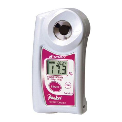
The Clamp-On Ground Resistance Tester Model P81001 allows for the safe,
fast and simple measurement of a grounding system with loop. There is no
need for auxiliary electrodes or breaking down grounding wires. The meter
can be used without disconnecting the ground under test.
The meter is equipped with a long jaw ideal for grounding with at steel
and is suitable for measuring when noise signals and harmonic waves are
present in the grounding network.
PRODUCT FEATURES
POWER TELECOMMUNICATIONS OIL FIELDS CONSTRUCTION INDUSTRIAL AND
ELECTRICAL EQUIPMENT
SAFETY
Carefully read the enclosed operating instructions before use and comply with precautions for
the best results from the meter and for your safety. This meter must be only used by qualied and
trained users.
APPLICATIONS
The meter is designed for use in the following applications:
STANDARD ACCESSORIES
The meter comes with the following standard accessories:
• 1 Verication resistor
• 4 AA 1.5 V dry cell batteries
• 1 Carrying case
PRECAUTIONS
• Only operate within the parameters of the given measuring range and environment.
• Keep the meter away from any impact, especially jaw contact planes.
• Remove batteries if the meter will be stored for long periods.
• Only authorized engineers should disassemble, calibrate and perform maintenance on the meter.
• If hazards result from continuous use, stop using immediately and send for repair.

4Clamp-On Ground Resistance Tester | MODEL P81001 Clamp-On Ground Resistance Tester | MODEL P81001 5
METER FEATURES
1. Liquid crystal display (LCD)
2. Trigger: Open and close jaw
3. Jaw: 65 mm (L) x 32 mm (W)
4. POWER button: Boot up/shut down/quit
5. HOLD button: Lock/release display
6. O/A: Switch of resistance and current
measurement condition
DISPLAY
1. Alarm: Indicates the measured value exceeds
the alarm value established in settings
2. Low battery voltage
3. Store data record
4. Review data record
5. Number in sequence of data records
6. Current unit
7. Resistance unit
8. Noise signal
9. Data hold
10. Open jaw indicator
11. Resistance measured lower than 0.01 Ω
12. Metric decimal point
13. 4-digit display
SPECIAL SYMBOL DESCRIPTIONS
1. Open jaw: The jaw is open and unavailable for
measurement. The trigger may be pressed or the jaws may
be unavailable due to pollution. (see Figure 3)
2. Low battery voltage: Battery voltage is lower than 5.3 V
and must be replaced to ensure accuracy.
3. OLQ: The measured resistance exceeds the upper limit of
the meter.
4. L0.01 Ω: The measured resistance exceeds the lower limit
of the meter.
5. MEM: Storing data records.
6. MR: Data records and number of records.
7. NOISE: Noise current is present in the earth
resistance to measure. The accuracy of measurement
cannot be guaranteed.
TECHNICAL SPECIFICATIONS
• Power source: 6VDC (4 alkaline batteries)
• Working temperature: -10 to 55 °C
• Relative humidity: 10-90%
• LCD: 4-digital LCD, 47 X 28.5 mm in length
• Jaw span: 28 mm
• Jaw size: 65 x 32 mm
• Meter quality (including batteries): 1320 g
• Meter size: 293 mm (L) x 90 mm (W) x
66 mm (H)
• Protection level: Double insulation
• Featured: By clamp
• Range shift: Automatic
• External magnetic eld: <40 A/m
• External electric eld: <1 V/m
• Single measuring time: 1 second
• Maximum resolution of resistance
measurement resolution .001 Ω
• Range of resistance measurement range:
0.01-1000Q
• Range of current measurement: 00.0-30.00 A
• Frequency of current: 40-65 Hz
• Number of record sets stored: 99 sets
• Range for alarm of resistance: 1-199Q
• Range for alarm of current: 1-499mA
3
2
4
Ω / A
5
6
1
Ω
Ω
8888
88
~
(1)
Ω
Ω
8888
88
(13)
(12)
(6)
(7)
(2) (3) (4) (5)
(11) (10) (9) (8)
GROUND RESISTANCE TESTER
RANGES AND ACCURACY OF EARTH RESISTANCE MEASUREMENTS
Range Resolution Accuracy
0.010 - 0.099 Ω0.001 Ω( ± 1% + 0.01 Ω)
0.10 - 0.99 Ω0.01 Ω( ± 1% + 0.01 Ω)
1.0 - 49.9 Ω0.1 Ω( ± 1.5% + 0.1 Ω)
50.0 - 99.5 Ω0.5 Ω( ± 2% + .5 Ω)
100 - 199 Ω1 Ω( ± 3% + 1 Ω)
200 - 395 Ω5 Ω( ± 6% + 5 Ω)
400 - 590 Ω10 Ω( ± 10% + 10 Ω)
600 - 1000 Ω20 Ω( ± 20% + 20 Ω)
A/C Leakage Current
Range Resolution Accuracy
0-80mA 0.05mA (±2.5%+1mA)
80mA-650mA 0.5mA (±2.5%+2mA)
650mA-4A 5mA (±2.5%+10mA)
30A 10mA (±2.5%+20mA)
Figure 2
Figure 1
Figure 3

6Clamp-On Ground Resistance Tester | MODEL P81001 Clamp-On Ground Resistance Tester | MODEL P81001 7
REFERENCE CONDITIONS
OPERATIONS
START-UP CALIBRATION
Before start-up calibration, press the trigger several times to
ensure the jaws are closed. Press the POWER button to start
the meter. Do not operate the trigger or clamp wires during
start-up calibration.
The meter is ready for resistance measurement when OL
appears on screen after inspection (see Figure 4).
INSPECTION
During inspection of the meter, DO NOT do any the following
which may make measurements inaccurate.
• Press the trigger
• Open the jaw
• Clamp a wire
• Overturn the meter
• Impose any external force on the jaw
If jaws clamp around a conductor loop during inspection,
all following measurements will be inaccurate. Remove the
conductor loop and restart.
SHUTDOWN
• Press the POWER button to turn the meter o.
• Five minutes after startup, the LCD screen will begin
ashing. The meter will automatically shut down after 30
seconds of ashing to preserve battery life. To resume
working status, press the POWER button when ashing.
• During the HOLD state, press the HOLD button to quit the
HOLD state. Then press the POWER button to shut down.
RESISTANCE MEASUREMENT
• After start-up inspection is completed, OL is displayed
indicating the meter is ready to proceed with resistance
measurement.
• Press the trigger to open the jaw and clamp the loop to
measure read out resistance value.
• A buzzing sound during measurement is normal.
• If necessary, self-calibration can be done with verication
resistor in standard accessory as shown in the following
gure. The reading should be consistent with the normal
value on verication resistor (5.1 W). The calibrated value
of verication resistor is in condition of temperature of
20 °C. It is normal to nd a dierence of numerical 1 word
between the shown value and nominal value.
If nominal value of verication resistor is (5.1 W), showing 5.0
W or 5.2 W is normal and accepted, showing OL indicates
that the measured resistance value exceeded the upper limit
of this meter. Showing 1.0.01 W indicates that the measured
resistance value exceeded the lower limit of this meter.
CURRENT MEASUREMENT
When the meter shows OL in mode of resistance
measurement after booting self-inspection, press the W/A
button to enter current measurement mode. If the meter
shows 0.00 mA, press the trigger to open the jaw and clamp
the loop to measure read out current value.
Showing OL as in Figure 6 indicates that the measured
resistance value exceeded the upper limit of this meter.
Conditions Reference
Ambient (20±3 °C)
Relative Humidity 50% RH ± 10%
Battery Voltage 6 V ± 0.51/
External Magnetic Field <40 A/m
External Electric Field <1 V/m
Operating Position Clamp horizontal
Position of Conductor in the Clamp Centered
Proximity to Metallic in the Clamp >10 cm
Loop Resistance Non-choke resistance
Rate of Distortion <0.5%
Interference Current On measurement
of loop resistance
Nil
Ω
OL
Figure 4
Figure 5
Ω / A
~
Figure 6
0L

8Clamp-On Ground Resistance Tester | MODEL P81001 Clamp-On Ground Resistance Tester | MODEL P81001 9
DATA LOCK/RELEASE/STORE
• In resistance or current measurement mode, press the
HOLD button to lock the current value displayed, with the
HOLD symbol showing. Press the HOLD button again to
unlock until the HOLD symbol disappears. Then the meter
reverts to a state of measuring.
• Press the POWER button for more than 3 seconds in the
measuring state. When the symbol MEM displays, the
meter numbers and stores the measured values as a
group of data in sequence, and the number displays in the
top right corner of the LCD panel.
• Press the POWER button for less than 3 seconds to exit
the save state.
Figure 7
The meter saved the measured resistance 0.016 W as No. 1
data record.
Figure 8
The meter saved the measured current 278 mA as No. 60 data
record. The meter memory is full as shown MEM. Stored data
remains when shut down.
DATA REVIEW
• Press the HOLD button for more than 3 seconds. The MR
symbol displays as Figure 8. The meter is in review stored
data mode and displays the data of Group 01 stored by
default.
• Press the HOLD button for less than 3 seconds to review
all stored data downward. It will automatically return to
No. 01 after last record is shown.
• To delete all stored data, press the POWER button.
• Press the HOLD button for more than 3 seconds to quit
data reviewing mode.
SETTING CRITICAL VALUE FOR ALARM
In measuring mode of resistance (see Figures 9 and 10), press
the HOLD button to switch digits from highest to lowest.
Press the Ohm/A button to set the critical value of alarm to
revert to measuring mode.
Figure 9
Setting critical alarm of resistance
Figure 10
Setting critical value of alarm by current
Ω
0 0 I6
60
Ω
Ω
Ω
Ω
Figure 7
Figure 8
Figure 12
Figure 13
Figure 9
Figure 10
Figure 11
REVIEW ALARM SETTING
• In measuring mode of resistance or current, press the
W/A button for 3 seconds to examine the critical value
of alarm.
• If the top digit ickers, the value examined refers to the
amount set last time.
• Within another 3 seconds of pressing the W/A button, the
meter will go back to measurement.
In Figure 11, the critical value for alarm by resistance set the
last time is 20 Ω.
Figure 11
Flickering digit
Figure 12
The measured resistance is under 0.01 Ω.
Figure 13
Loop resistance measured is 5.1 Ω.
Figure 14
Loop resistance measured is 2.1 Ω. Current reading was
locked: 2.1 Ω.
Figure 15
No. 26 data record is stored. Loop resistance measured is
0.028 Ω.
Figure 16
Alarm indicates the measured resistance exceeds alarm value
settings. No. 8 data record is stored. Resistance measured is
820 Ω.
MAINTENANCE
• Turn the switch to the OFF position for cleaning. Open the
clamp jaws and check all surfaces are free of dust, dirt or
foreign substances.
• Clean if necessary to ensure measurement accuracy. Do
not use harsh detergents, solvents or cleaners. Only clean
with a damp cloth.
Ω
Figure 14
Ω
26
Figure 15
Ω
08
Figure 16

10 Clamp-On Ground Resistance Tester | MODEL P81001 Clamp-On Ground Resistance Tester | MODEL P81001 11
MEASUREMENTS
MEASUREMENT POINT SELECTION
Select a proper point for measurement for accurate results.
Refer to Figure 17.
POINT A: When the spur track measured is out of circuit, the
meter displays OL. Select a dierent measurement point.
POINT B: When the spur track measured is a circuit formed
by a metal conductor, the meter displays OL or the resistance
value of a metal circuit. Select a dierent measurement point.
POINT C: Earth resistance of the spur track is measured.
Measuring earth resistance of an oil tank and
loading point
Figure 18 represents a grounding system in a gas station
oil tank, where earth pole A connects to the oiling machine
and loading point earth pole C is an independent earth
pole. Another independent earth pole is found as assistant
earth pole B (such as the underground water pipe, etc.), and
respectively measures out values of RI, R2 and R3 by the
meter according to a three-point method.
Results:
Earth resistance of oil tank R A = (R1 + R2 = R3)
Earth resistance of assistant earth pole R B = R1 – RA
Earth resistance of loading point R C = R2 – RA
Note: When measuring R1, make sure there is no conductor
link between BC and ACV which is requested for measuring
R2 and R3.
Measuring earth resistance of an oiling machine
As shown in Figure 19, nd an earth pole which is apart from
the earth pole of the oiling machine, such as the earth pole of
the loading point. Connect the two points with the test line
and measure the value RT with the meter.
Results:
Earth resistance of oiling machine R = RT - RC
RT is the resistance measured by the meter.
RC is the earth resistance of loading point.
Measuring link resistance of an oil hose on an oiling
machine
Connect the oiling machine and refueling gun with a test line.
Measure the value RT with the meter.
Results:
Link resistance of the oil hose of the oiling machine
R = RT – RL
RT is the resistance measured by the meter.
RL is the resistance of the test line.
A
C
B
B
Figure 17
Figure 19
Figure 20
Figure 18

12 Clamp-On Ground Resistance Tester | MODEL P81001 Clamp-On Ground Resistance Tester | MODEL P81001 13
Important notes for measuring earth resistance
There can be a considerable dierence when comparing
testing values measured by a meter versus a traditional
voltage and current method.
Whether unclasped (grounding body to measure is separated
from grounding system) has been done when measuring
resistance by traditional voltage and current method. If not,
the earth resistance that is measured refers to the parallel
connection value of earth resistance of all grounding bodies.
It is not benecial to measure parallel connection value of
earth resistance of all grounding bodies. Measuring earth
resistance is making a comparison between the earth
resistance and a permitted value regulated by relevant
standards to decide whether earth resistance is qualied.
For example, earth resistance per radix tower refers to
the resistance measured when a grounding body cuts o
electric connection with a ground wire. If the grounding body
doesn’t cut o electric connection with a ground wire, earth
resistance measured refers to the parallel connection value of
earth resistance of multi-radix towers.
ON-SITE APPLICATION
Application in power systems
(1) Measurement for earth resistance of power transmission
line tower
The grounding of power transmission line tower forms
a multi-point grounding system. To measure of earth
resistance, clamp grounding rods with the meter.
(2) Measurement for earth resistance of neutral point of
transformer
There are two cases in neutral point grounding of
transformers. If multiple grounding is applied, it is a multi-
point grounding system. All other cases are single-point
grounding.
For measurement, if the meter shows L0,01 Q it may mean
that the same pole and tower or transformer has more than
two grounding rods linked together underground. Unveil
other grounding rods and keep one rod remaining.
(3) Application in substation of power plant
The meter can check the status of touch and link in circuits.
With assistance from a line, it can measure link status
between equipment’s in-station and earth grid. Earth
resistance is measured according to single-point grounding.
Application in telecommunication systems
(1) Measurement of earth resistance of machinery room in
telecom building
The machinery rooms for telecommunication systems are
often placed on a high oor of the building, which can make
it diicult to measure. It can be measured with the meter by
linking a re hydrant and grounding electrode to measure
with a test line (re hydrant is equipped in the machinery
room). Measure the test line with the meter.
Reading of resistance = earth resistance of machinery
room + resistance of testing line + earth resistance of
re hydrant
(2) Measurement of earth resistance of machinery room and
transmitter tower
Grounding of machinery room and transmitter tower usually
forms a two-point grounding system as shown in Figure 21.
• If the measured value of the meter is lower than the
permitted value of earth resistance, earth resistance of the
machinery room and transmitter tower is qualied.
• If the measured value of the meter is higher than the
permitted value of earth resistance, apply measurement
of single-point grounding.
Figure 21

14 Clamp-On Ground Resistance Tester | MODEL P81001 Clamp-On Ground Resistance Tester | MODEL P81001 15
Application in lightning-prevention grounding system of
buildings
If grounding electrodes of the building are separated from
each other, earth resistance of various electrodes can be
measured according to the following image.
Figure 22
Lightning-prevention overhead conductor
Application in grounding system in gas stations
In an environment full of explosive gas, such as a gas station,
oil eld and oil groove, it is necessary to adopt explosion-
proof products. Generally, gas stations are requested to
ensure earth resistance and link resistance as follows:
Variations in the nominal working range
Number Item to Measure Technical
Requirement
1 Earth resistance of oil tank ≤ 10 Ω
2 Earth resistance of loading point ≤ 10 Ω
3 Earth resistance of oiling machine ≤ 4 Ω
4 Link resistance of oil hose of oiling machine ≤ 5 Ω
Distortion quantity Limit of operating range Distortion
Temperature -10 °C to 55 °C 1.5 class of
accuracy per 10
Relative humidity IO% RH to 90% RH 1.5 class
Battery voltage 5.5 V to 6.5 V 0.25 class
Conductor position From edge to center 0.1 class
Clamp position ± 180° 0.5 class
Proximity of magnetic mass 1 mm steel plate
against jaw face 0.25 class
Magnetic eld 50-60 Hz 400 A/m 0.25 class
Electric eld 50-60 Hz 0-10 KV 1 m 0.25 class
Figure 22
Learn more about how
our Utility Pro Products
can transform your
operations.

16 Clamp-On Ground Resistance Tester | MODEL P81001
Transforming tomorrow.
www.sncmfg.com
MANUFACTURING CO., INC.
Table of contents
