A38E – 514252-201
iii
Service and Parts Information
Ordering Parts
When placing an order for service or repair parts, please
have the following machine information readily available.
yModel number
ySerial number
ySnorkel part number
yDescription of part
yQuantity of parts required
yYour purchase order number
yAddress for order to ship to
yThe desired shipment method
If ordering parts off-line, the parts order form on the
following page may be mailed or faxed to the attention
of the Parts Department at the following location:
Snorkel North America
P.O. Box 1160
St. Joseph, MO 64502-1160 USA
Phone: 1-800-255-0317
Parts Fax: 1-785-989-3077
Snorkel Europe
Vigo Centre
Birtley Road
Washington
Tyne & Wear
NE38 9DA
Phone: +44 (0) 845 1550 058
Parts Fax: +44 (0) 1952 607 678
Attention: Parts Department
For your convenience, our electronic on-line ordering
system is accessible from the following Internet location:
http://www.snorkellifts.com
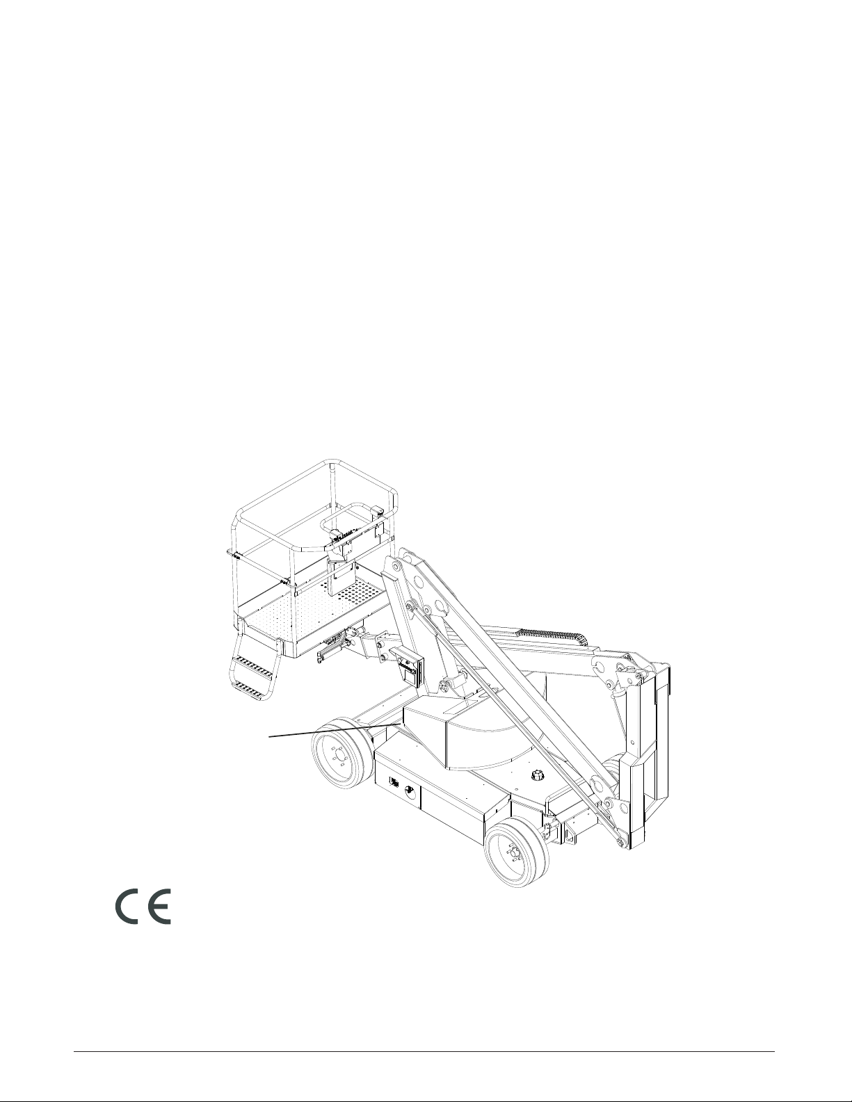
CE Compliance
All users and service personnel using or working on the
aerial platform must read, understand and comply with
all applicable regulations. Refer back the the Operators
Manual for more information on safe use.
The A38E work platform meets and exceeds the require-
ments of En280:2013+A1:2015
ANSI and OSHA Compliance
All owners,users of the aerial platform must read, un-
derstand and comply with all applicable regulations.
Ultimate compliance to OSHA regulations is the respon-
sibility of the user and their employer.
ANSI publications clearly identify the responsibilities
of all personnel who may be involved with the aerial
platform. A reprint of the “Manual of Responsibilities
for Dealers, Owners, Users, Operators, Lessors and
Lessees of ANSI A92.5 (1992) Self-Propelled Elevating
Work Platforms” is available from Snorkel dealers or
from the factory upon request.
Copies are also available from:
Scaffold Industry Association, Inc.
P.O. Box 20574
Phoenix, AZ 85036-0574 USA
Manuals
Manuals are available from Snorkel to support any of
the machines that we produce.
The specic manuals for A38E aerial platforms are as
follows:
A38E Operator’s Manual ANSI / CE
Snorkel part number – 514252-001-EN
S3219E Repair Parts Manual
Snorkel part number – 514252-201-EN
ANSI Manual of Responsibilities
ANSI A92.5 (1992)
Snorkel part number – TBA
Machine Information
Model Number:
Serial Number:
Date of Purchase:
Purchased From:
Snorkel Dealer or Distributor: