Snow Performance BOOST COOLER 50005 User manual

INSTALLATION INSTRUCTIONS
FOR PART #50005
DIESEL STAGE 3 MPG-MAX™
WATER / METHANOL INJECTION
SYSTEM
7.3L POWERSTRO E
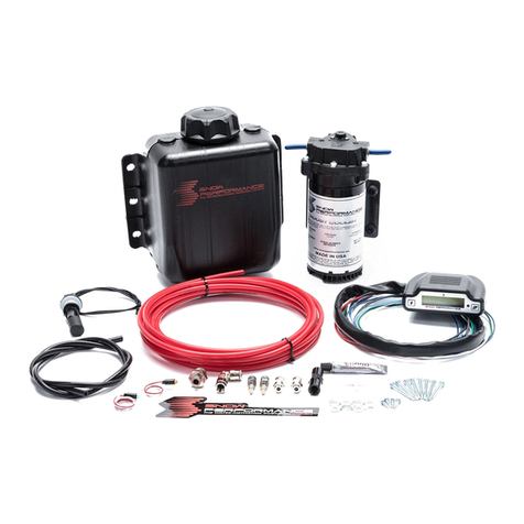
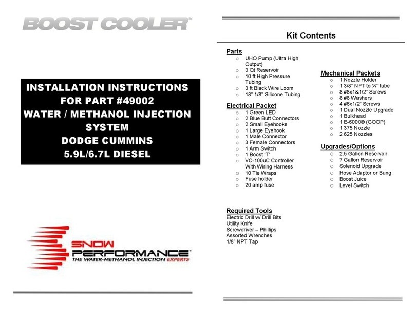
Kit Contents
Parts
o 7 Gallon Reservoir
o UHO Pump (Ultra High
Output)
o 25 ft High Pressure
Tubing
o 3 ft Black Wire Loom
o 18” 1/8” Silicone Tubing
Electrical Packet
o 2 Blue Butt Connectors
o 3 Small Eyehooks
o 1 Male Connector
o 3 emale Connectors
o 10 Tie Wraps
o 1 Arm Switch
o 1 Brass Hose Barb
o 5” Double Sided Tape
o 1 Yellow Temp Probe
Connector
o Diesel Stage 3 MPG
Max Controller
o Temperature Probe
o use holder
o 20 amp fuse
Required Tools
Electric Drill w/ Drill Bits
1/8” – 27 NPT Tap
Screwdriver – Phillips
Assorted Wrenches
Mechanical Packets
o 1 Nozzle Holder
o 4 #8x1&1/2” Screws
o 4 #8 Washers
o 2 Dual Nozzle Upgrades
o 2 Solenoid Upgrade
o 7 Gallon itting Set:
o 90° Elbow
o 3/8” – 1/8” Reducer
o 1 Temp Probe Compression
itting – 3/16”
o 1 E-6000 (GOOP)
o 1 175ml/min Nozzle
o 1 375ml/min Nozzle
o 1 625ml/min Nozzle
Upgrades/Options
o 2.5 Gallon Reservoir
o Hose Adaptor or Bung
o Boost Juice

Introduction
The Snow Performance Boost Cooler® Diesel Stage 3 MPG-MAX™
water/methanol injection system provides more power, cooler EGTs, and
excellent fuel economy increases. The MPG-MAX™ system does not
require a sustained high load state in order to provide maximum fuel
economy gains. The MPG-MAX™ system uses a new injection
management controller that allows for a small spray of water/methanol to
be injected across the power curve. This provides an increase in
combustion efficiency which provides more power without injecting more
diesel fuel. This increase in efficiency translates into an increase in fuel
economy. Typical fuel economy increases are 10%-15% or 1-3 MPG.
The MPG-MAX™ system has a secondary output that is used to activate
a Power Mode. This introduces a second phase of injection. A larger
nozzle(s) is used to inject more fluid to make more power. The Power
Mode activation point is adjustable for best performance.
Because the MPG-MAX™ system injects more frequently, the fluid
consumption rate will be higher than other Boost Cooler systems. The
MPG-MAX™ system has been coupled with the Snow Performance 7
Gallon Reservoir to provide a large fluid tank that fits well into the bed of
a truck. This will provide the longest range possible and includes the
necessary installation hardware.
Refer to the follow installation diagram. Completely read through this
instruction manual before attempting installation. Contact Snow
Performance for any questions or concerns.
Nozzle Identification Chart:
Nozzle
Number Nozzle Size
Nozzle
Number Nozzle Size
1 60 ml/min
4 225 ml/min
2 100 ml/min
5 375 ml/min
3 175 ml/min
6 625 ml/min

Note: The diagram shows three nozzles, but in most applications two
nozzles will provide the optimal flow. See page 8 for details.
Installation - Mechanical
Step 1 Reservoir Install
• Install 90 degree elbow into reducer bushing using E6000
sealant. Turn ½ turn past finger tight. Do not use Teflon sealants
on Snow Performance fittings. Install reducer bushing into
reservoir outlet using E6000 sealant. Turn ½ turn past finger
tight.
• Test fit reservoir in desired mounting location. Typical placement
is tucked up along the side of a pickup bed or in a bed mounted
tool box.
• Check the area under the bed near the desired mounting
location. Note the location of fuel tanks, fuel lines, and wiring.
• Mark the location of the four aluminum mounting strap tab bolt
holes.
• Drill through bed with appropriately sized drill bit. USE
CAUTION WHILE DRILLING.
• Mount reservoir with aluminum mounting straps using
appropriate hardware.
Caution******
To avoid gravity feeding of fluid with rear mount reservoirs, it is essential
to use a solenoid in-line between the reservoir and pump. Do not
operate your rear mount equipped vehicle without a solenoid installed.
Step 2 Pump Install
Mount the pump so the inlet is positioned at the lowest point of the
reservoir or lower. Pump can be mounted horizontally or vertically using
the supplied screws and washers. Ensure that no sharp bends in the
high pressure tube occur near the pump. Sharp bends can cause stress
on the inlet and outlet ports of the pump, causing leaks. Trim tube with a
utility knife or razor blade, making sure to eliminate any burrs or kinks on
the end. Insert firmly into the pump about ½ inch through the light grey
locking collar. Note the arrows indicating flow direction on the top of the
pump. To remove the hose, gently and evenly push the light grey locking
collar into the head unit of the pump, then pull on the hose gently.

Measure the distance from the reservoir outlet to the pump inlet. Cut the
¼” red tubing using utility knife. Make cuts are as square as possible.
Ensure there are no kinks in the tubing and insert tubing into quick
disconnects at pump and reservoir until fully seated. Keep the pump
within 2 feet of the reservoir. The pump can be mounted under the truck
bed in a place protected from road spray.
Caution******
Pump must be shielded from road debris and tire wash.
ailure to do so will result in pump failure
Step 3 Nozzle Selection
Nozzle sizing is a function of horsepower, which approximates the
engine airflow, and boost, which approximates intake charge heat.
Recommended starting points:
HP MPG MAX POWER MODE
350 > WHP 175 ml/min 375 ml/min
400 - 500 WHP 175 ml/min 625 m/min
500 < WHP 175 ml/min 375 + 625 ml/min
Seal the nozzle into the nozzle holder using GOOP®
sealant. Using a sealant that is not permanent will
allow for nozzle changes during tuning. Simply remove the nozzle,
clean the threads, and reinstall using sealant.
Assemble desired nozzle into nozzle holder using E6000® sealant. The
end of the nozzle with the fine mesh screen is to e inserted into
the nozzle holder. Torque 1/2 turn past finger tight. Do not use Teflon
sealants on Snow Performance fittings.
Correct
Incorrect
Step 4 Nozzle Mounting
The nozzle assembly should be installed 90° to the direction of airflow.
On round intake tubes, this is 360° around the tube meaning the nozzle
can be mounted in any direction. This will ensure maximum cooling as
the nozzle sprays in a cone pattern. Choose and mark mounting location
for nozzle placement. Nozzles can be placed on the charge pipe
between the intercooler outlet and the intake inlet, in a location that
allows an unobstructed spray pattern into the airflow.
Remove the selected piece and drill and tap (11/32" pre-drill, 1/8”-27
NPT tap) for two nozzles. Note that NPT is a tapered thread, and be
cautious not to over-tap thin walled pipes. Test fit nozzles into the pipe to
ensure a tight fitment.

The nozzle is mounted using its external 1/8 NPT threads. Tighten the
nozzle and nozzle holder assembly one half turn past finger tight using
E6000® to seal the threads.
Step 5 Nozzle and Solenoid Connection
Solenoid is flow directional. Be sure to note which port is the
INLET/PRESSURE port (2 or IN) and which is the OUTLET port (1 or
OUT).
The main outlet line coming from the Reservoir connects to the first
solenoids inlet. The outlet of this solenoid connects to the inlet of
the pump. The outlet of the pump connects to the Union “T”. One
outlet of the tee goes to the small MPG-MAX™ nozzle and the other
outlet of the tee connects to the second solenoid. The outlet from
the second solenoid will connect to the POWER MODE nozzle(s).
Measure the distance from the pump outlet to the injection location. Cut
the ¼” red tubing using utility knife. Make cuts are as square as
possible. Ensure there are no kinks in the tubing and insert tubing into
quick disconnects until fully seated. Gently pull on tubing to ensure a
good connection. Use tie wraps to help route tubing and to ensure it
doesn't contact moving or hot parts in the engine compartment
Step 6 Install EGT Probe
Drill and tap exhaust manifold pre-turbo. If this is performed with the
exhaust manifold still on the engine, start the engine and let it idle while
drilling and tapping. This will prevent shaving from entering the exhaust
and turbo. During tapping, coat tap with heavy grease so it will collect
any metal shavings.
Mount the Temp Probe using the 3/16” compression fitting (provided).
Installation - Electrical
Variable Controller Installation
Attach controller to secure location with easy access in driver’s
compartment using supplied tape. Install brass hose barb into intake
tubing 3” prior to nozzles. Connect black silicone tubing from brass hose
barb to clear tubing coming from the controller and secure with a tie
wrap.

CAUTION: Disconnect the negative attery terminal while
connecting wires to prevent electrical fire or damage to controller.
• Connect BLACK wire to a good ground location.
• Connect WHITE wire to Pump RED power wire.
• Connect GREEN wire to one BLACK wire from solenoid. Connect
other solenoid BLACK wire to ground.
• Connect RED wire to inline switch and then connect to +12V key on
source.
• Wire the Yellow “K” type temp probe connector to temp probe
installed in Step 6 above. The YELLOW wire connects to the
POSTITIVE terminal, the RED wire connects to the NEGATIVE
terminal of the connector. Connect to the lead from control module.
Always have a good electrical ground connection.
Poor ground will result in erratic operation.
Controller Operation
The controller has an LCD display screen. The display software allows
for seven different display modes and three control/setup screens.
To control the screen selection, the unit has two operator buttons; one to
the left of the screen (button 1) and one to the right of the screen (button
2). Pressing and releasing button 1 will cause the display to sequence to
the next screen. Button 2 is only active in the control/setup screens, and
is used to change the current control setting of the setup screen
displayed.
The system memory will remember the current display setting even if the
unit is turned off. The controller will turn on at the last used display
setting.
Additionally, button 2 is used for the “Injection ON/O ” function.
Note: When the Red LED to the left of utton 2 is illuminated,
the controller is activating the power nozzle.
Pressing and holding utton 2, then pressing utton 1, then
releasing oth uttons will change the system to read only without
changing the display screen. The pump will not activate in read
only. All screen display functions will remain active even when the
injection is turned off. To get the controller out of read only mode,
just repeat the procedure.
Screen 1
This mode displays pressure (P), temperature (T) and injection
percentage (Inj) as three independent bar graphs.
Screen 2
This mode displays the boost pressure and EGT temperature in PSI and
degrees .
Screen 3
This mode displays the boost pressure and EGT temperature in BAR
and degrees C.
P T
Inj
Boost
EGT
Boost
EGT

Screen 4
This mode displays the boost, EGT and injection in Standard units.
Screen 5
This mode displays the Boost, EGT and Injection in Metric units
Screen 6
This display shows both digital and bar graph readings for boost and
EGT in Standard units.
Screen 7
This display shows both digital and bar graph readings for boost and
EGT in Metric units.
Screen 8
This is the setup screen for the control mode. Pressing the right button
(# 2) will toggle the setting between MPG and TOW. If TOW is on, the
2-D matrix value for the injection is used. If MPG is on, injection will be
100% controlled by boost.
Screen 8A
MPG MODE START - UP. Pressing and releasing button 2 will increase
the injection activation point. Typical activation points are 6-8 psig.
Screen 8B
MPG MODE START - DOWN. Pressing and releasing button 2 will
decrease the injection activation point.
Screen 8C
MPG MODE 100% - UP. Pressing and releasing button 2 will increase
the maximum injection point. Typical 100% points are 13-18 psig.
Screen 8D
PSI Deg T
%Inj
BAR DegC
%Inj
PSI
Deg
Bar
DegC
Injection Mode
Change
MPG Mode Start
PSI Up
MPG Mode Start
PSI Down
MPG Mode 100%
PSI Up
MPG Mode 100%
PSI Down
MPG MODE 100% - DOWN. Pressing and releasing button 2 will
decrease the maximum injection point.
Screen 9-(TOW MODE ONLY)
This screen is used to select between LOW, MED, and HI boost when in
TOW mode. For vehicles making 8-18 psig of oost, use LOW
mode. For vehicles making 18-25 psig of oost, use MED mode.
For vehicles making 25+ psig of oost, use HI mode.
Screen 10-(TOW MODE ONLY)
This screen is used to increase the injection gain setting. Pressing and
releasing button 2 will increase the gain setting. 5%-10% changes in
gain will make significant changes in injection while in TOW Mode.
Screen 11-(TOW MODE ONLY)
This screen is used to decrease the injection gain setting. Pressing and
releasing button 2 will decrease the gain setting.
Screen 12 –(MPG MODE ONLY)
POWER MODE START - UP. Pressing and releasing button 2 will
increase the Power Mode injection activation point. Activate Power
mode 6-10 psig efore maximum oost.
Screen 13-(MPG MODE ONLY)
POWER MODE START - DOWN. Pressing and releasing button 2 will
decrease the Power Mode injection activation point.
Variable Controller Tuning
MPG MODE
When MPG mode is selected, injection is a function of boost pressure
only which is desirable when a more immediate injection is desired. With
the MPG mode function activated, an injection start and full point must
be selected.
• Toggle to Screen 8. Select MPG mode.
Boost Range
Change
Inj Gain
Increase
Inj
Inj Gain
Decrease
Power Mode Start
Up
Power Mode Start
Down

• Toggle to Screen 8A/B. Adjust the start point up or down.
Typical start points are 7-8 psig.
• Toggle to Screen 8C/D. Adjust the full 100% point up or down.
Typical 100% points are between 16 and 20 psig.
• Toggle to Screen 9. Select boost level. See “Controller
Operation: Screen 9”.
• Toggle to Screen 12/13. Adjust the POWER MODE activation
point up or down. Initially set the POWER MODE start point to
activate 6-10 psig of your maximum boost pressure. If the max
boost pressure is 30 set the POWER MODE start point to 20-24
psig. If the max boost pressure is 40 set the POWER MODE
start point to 30 psig.
A typical application making 28 psig maximum boost and hitting 7psig
under normal acceleration should select the “HI” Boost range and leave
gain at 100%. MPG Start should be set at 6 psig and MPG 100% should
be set at 14 psig. POWER MODE should be set at 22 psig.
Most 7.3 applications will make around 20 psig stock, and with average
bolt-on modifications reach about 30 psig. A stock 7.3 will usually use the
“MED” boost range rather than the “HI” boost range. A modified 7.3 will
usually use the “HI” boost range.
Tow MODE
When Tow mode is enabled, the controller will measure EGTs and boost
pressure to calculate the injection rate. Based on these two inputs, the
controller uses pre-mapped 2-D matrix to determine how much fluid to
inject. This is ideal in heavily loaded or towing situations. Because the
controller is pre-programmed, there are no start and full points to adjust.
• Toggle to Screen 8. Select Tow mode.
• Toggle to Screen 9. Select boost level. See “Controller
Operation: Screen 9”.
• Toggle to Screen 12/13. Adjust the POWER MODE activation
point up or down. Initially set the POWER MODE start point to
activate 6-10 psig of your maximum boost pressure. If the max
boost pressure is 30 set the POWER MODE start point to 20-24
psig. If the max boost pressure is 40 set the POWER MODE
start point to 30 psig.
ADJUSTING THE CONTROLLER
The MPG MAX phase of injection is meant to inject a small amount of
fluid during moderate load cruising. If combustion quench occurs as
evidenced by engine bucking or bogging, too much fluid is being injected
too soon. To prevent quench try each of the following:
• Toggle to Screen 8A. Adjust the MPG MODE START point to
come on at a higher boost level.
• Change out MPG MAX nozzle to the next size smaller.
If quench occurs when the POWER MODE activates try each of the
following:
• Toggle to Screen 12. Adjust the POWER MODE START point to
come on at a higher boost level.
• Toggle to Screen 11. Adjust the GAIN down to reduce overall
injection amount if in Tow Mode.
• Change out POWER MODE nozzle(s) to the next size smaller.

Activation of pump for short periods (1 - 5 sec.) will purge air bubbles
from the system. This can be accomplished during initial use.
Step 2 Test Controller
• With the nozzles removed from the intake, place the controller in
MPG mode. Set boost mode start to 1 PSI.
• Using a hand pump, apply 10-20 psig of pressure to the boost
line on the controller.
• Pump should activate, fluid should flow, and tank level should go
down.
Tuning Quick Reference
If combustion quench occurs as evidenced by engine “bucking”, reduce
the injection quantity. This can be done by:
1. Using a smaller nozzle(s).
2. Using Screen 9 and Screen 10 to adjust the gain.
Caution******
Prolonged quench may cause lower engine damage over a period of
time.
Also, fresh methanol – less than 1 month old when exposed to
atmosphere – and using a greater methanol concentration – up to 50% -
will reduce combustion quench.
100% water will cool combustion and EGTs and will increase power
approx 20-30 HP.
75/25 water/methanol will reduce EGTs and power will increase
approximately 40 HP.
50/50 water/methanol will reduce EGTs and increase power
approximately 70+ HP.
Caution: To avoid “pooling” in the intake it is recommended that:
1. The engine be run without water/methanol for at least 5 minutes after
injection before turning the engine off.
2. The “armed switch” is turned to the off position when the engine is off.
Testing the System
Note: for best results, prime pump before use
To clear air from the pump and insure that the system is primed:
• ill reservoir with water approx ¼ full.
• Remove tubing from nozzle (or solenoid if solenoid used in-line
between pump and nozzle) and run tube into separate container.
• Apply 12 VDC to red pump wire for approximately 5 seconds or
until fluid flow is consistent.
• Pump is now primed. Reconnect tubing from pump outlet to
nozzle (or solenoid).
If using a solenoid in etween the pump and the reservoir: Remove
the solenoid and place a solid piece of tube between the pump and the
reservoir and prime the system. Then replace the solenoid in between
the pump and reservoir.
Step 1 Test Pump and Mechanical System
Disconnect pump from controller. Using a 12 volt source, apply power to
red wire of pump. Pump should activate and fluid level in tank should go
down. It is recommended to also check the nozzle spray pattern while
following this procedure. Also check for leaks.
If pump goes on and fluid level doesn't go down, there is an obstruction
in the tube or nozzle.

Caution: Do not attempt to inject water/methanol until the engine has
reach operating temperature. A cold engine is more susceptible to
quench and poor performance.
Maintenance –
Remove nozzle(s) and clean screen filters at
least once per year using car cleaner.
The Boost Cooler® has een designed to operate with high
concentrations of methanol. Oil or other additives are not required
for system lu rication.
For est performance, cooling and system life it is recommend that
Snow Performance Boost Juice™ (#40008) e the exclusive fluid
used in the system.
Fluid Level Switch
Instructions
• Locate desired level switch mounting position. Suggested
placement is 1/5 of max reservoir height.
• Carefully drill side of reservoir using 13/16” bit. A step bit is
recommended for best drilling results. Hole
must be free of nicks or shavings for proper
sealing.
• Remove rubber seal from level switch.
Insert seal into reservoir until fully seated.
Goop can be used around the edges of the
hole.
• Lubricate exterior of level switch with water
and insert into seal until fully seated. Position level switch so GT
symbol is at six o’clock position.
• Wait 30 minutes for Goop to cure, then test for leaks. With fluid
level above level switch, float should be angled up. With fluid
level below level switch, float should be in horizontal position.
• Connect one black wire from level switch to ground.
• Connect other black wire from level switch to white wire from
LED.
• Connect red wire from LED to +12 volt key on power source.
Low luid LED
Red
Black
Black
FUEL SYSTEMS
SNOW PERFORMANCE
Table of contents
Other Snow Performance Automobile Accessories manuals
Popular Automobile Accessories manuals by other brands
BM PRO
BM PRO TrailSafe Series owner's manual
pro user
pro user DIAMANT I Assembly instruction and safety regulations
Caraudio-Systems
Caraudio-Systems usbLOGiC manual
Steel mate
Steel mate TP-S7 Fact sheet
OPT7
OPT7 Quantum Rock Lights Bluetooth installation guide
Electro motive
Electro motive XDI200 Installation manual & users guide
