Snow Performance Boost Cooler 20010-BRD User manual

Page | 1
Snow Performance Boost Cooler® Gas Water-Methanol Injection Kit Instructions
(Part #’s 20010/20010-BRD & 212/212-BRD)
Version: 1.0
Congratulations on your purchase of a Snow Performance Boost Cooler® Gas Water-Methanol
Injection kit! Keep these instructions for reference. First locate the part# of your injection system
which can be found on the front of the Boost Cooler® box. Use this number to identify which set of
electrical and setting instructions to follow.
Required Tools Needed For Install:
●
Phillips/Flat Head Screwdriver
●
Power Drill
●
Razor Blade
●
Preferred Electrical Connectors (Crimping/Stripping Tools, Blue Butts, Eye Hooks, Posi-Taps,
Fuse Taps, Soldering Supplies etc)
●
Spare 16 Gauge Wire (Optional Depending On Install)
●
Open End Wrench / Socket Set
●
1/8” – 27 NPT Tap (Optional Depending On Install)
Average Install Time: 4-6 Hours
CAUTION: You must completely read through these instructions before installing and operating
this product. Failure to do so can result in damage to this product and the vehicle.
Locate the wiring diagram for your injection kit further in these instructions beginning
on page 8 for overview of system layout before attempting install.

Page | 2
Step 1 Self Sealing Low Level Sensor Install (Optional)
Although not required for kit operation, the low level sensor and yellow led are a great way to monitor
the level of your water-meth tank. The level sensor is designed to turn on the led or alert the controller
in some kits as soon as the level inside the reservoir reaches the level of the sensor.
Step 1: Remove plastic nut, plastic ring, and clear rubber gasket from level sensor assembly.
Step 2: Using a stepped drill bit. Drill the hole for the level sensor at the location in the tank you want to
be alerted. Typical placement is 1/3rd of the tank height.
Step 3: Remove the cap from the tank and feed/pull wires through hole until level sensor is seated
against plastic stopper.
Step 4: Reinstall the clear rubber gasket,
plastic ring, and plastic nut onto the level
sensor.
Step 5: Push clear rubber in until flush with
outside of reservoir.
Step 6: Align the switch so the arrow is facing
down. If arrow faces another direction the
sensor will not operate.
Step 7: Tighten the plastic lock nut until the
rubber gasket pushes firmly on the wall of the
reservoir creating a leak free seal.

Page | 3
Step 2 Tank Install
OPTIONAL: If desired you can use the stock windshield washer fluid tank as the tank for your water-
meth system. Simply drill and tap a 3/8” NPT hole in desired feed spot for system and install the 3/8”
NPT fitting into the tank using E-6000 sealant on threads/around area.
BRAIDED LINE KITS ONLY: If OEM windshield washer tank is not being used, an upgrade exists to
move your tank to the trunk of any vehicle (See Part# SNO-40012-BRD) and other larger trunk mount
tank options (See Part# SNO-40014-BRD)
Step 1: Install 3/8” NPT to ¼” Quick Connect fitting or 3/8” NPT to 4AN Elbow fitting into the bottom of
the reservoir using E6000® sealant on the threads.
Step 2: After allowing the thread sealant todry, fill reservoir with water and check for leaks around tank
fitting and level sensor. Ifleak occurs use supplied thread sealant.
Step 3: Install the 3qt. tank with four (4) #8x1&1/2” self-tapping screws and four (4) #8 washers
(supplied) in desired mounting location. Typical placement isanyvoid area inside the engine bay.
The reservoir should be installed above the pump, but below the nozzle. This keeps
the pump primed and avoids fluid leaking into nozzle when not in use
CAUTION: To avoid gravity feeding of fluid with rear mount reservoirs, it is essential to use a
solenoid upgrade (Part # SNO-40060 / SNO-40060-BRD). Do not operate your rear mount reservoir
equipped vehicle without an anti-siphon solenoid installed.
Page | 4
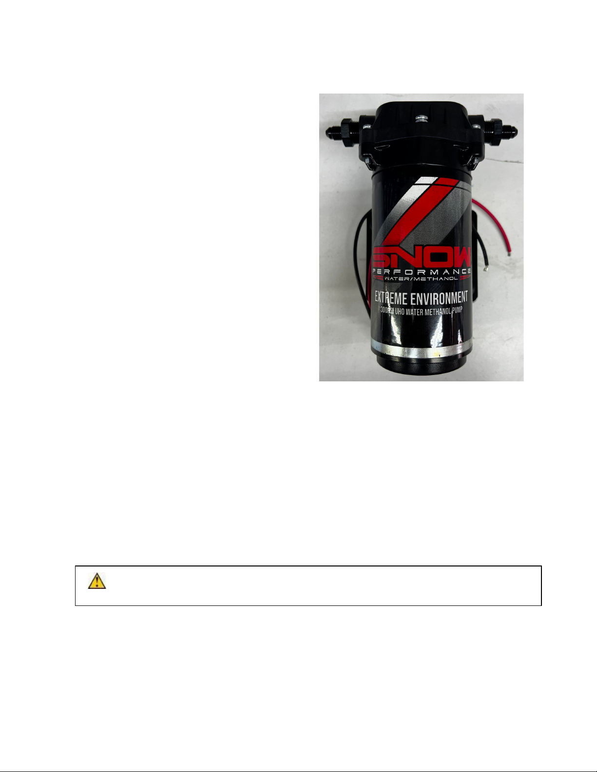
Step 3 Pump Install
Braided Line Kits Only- Install (2) 3/8” NPT to
4AN Straight fittings into the pump inlet and outlet
using E6000® sealant on the threads. Do not
overtighten as damage to the pump housing can
occur.
Quick Connect Kits Only-Remove the blue
rubber plugs from the quick-connect fittings by
first pushing the plug toward the pump, hold the
grey collar against the pump, and gently pull the
blue plug from the fitting. Warning: Pulling against
the quick connects with excessive force may
cause fitting damage.
Step 1: Position the fluid pump so that the inlet is
positioned at or below the lowest point of the
reservoir, and within two feet of the reservoir.
(Pump can be installed in any orientation). This
will ensure the pump is primed with fluid for
optimal flow and pressure to the nozzles.
**Arrows on the pump inlet and outlet indicate
the direction of fluid flow**
Step 2: Install the fluid pump with four (4) #8x1&1/2” screws and four (4) #8 washers (supplied) in
desired mounting location.
Step 3: Fit the high temp nylon tubing or braided line between the tank outlet fitting and the pump inlet,
ensuring there are no kinks in the line and there is no stress on the fittings. Sharp kinks/bends can
cause a leak in the system.
Braided Line Kits Only- Using the 2’ or 1’ stainless braided line section supplied in the kit connect the
tank outlet to pump inlet.
Quick Connect Kits Only- Once high temp nylon is measured from tank outlet to pump inlet cut tubing
using razor blade. Remove any burrs so that the fluid line properly seals against the internal o-rings
inside the quick connect fittings. Insert tubing into the quick connects until fully seated, and pull lightly
against quick connects to ensure proper installation between tank outlet to pump inlet
CAUTION: Pump must be shielded from road debris and direct tire wash. Failure to do so will
result in pump failure.

Page | 5
&RUUHFW &RUUHFW
**Teflon sealants are not compatible with methanol, and should not be used with the install of
your Snow Performance Boost Cooler**
Step 4 Nozzle Selection
/RFDWH\RXU+\SHU6RQLFZDWHUPHWKDQROQR]]OHVLQWKHNLWDQGFRPSDUHWKHQXPEHUVWDPSHGRQWKH
VLGHWRWKHDERYHFKDUWWRGHWHUPLQHLWVVL]H1R]]OHVL]LQJLVGHWHUPLQHGE\KRUVHSRZHUZKLFK
DSSUR[LPDWHVWKHHQJLQHDLUIORZDQGERRVWZKLFKDSSUR[LPDWHVLQWDNHFKDUJHKHDW
'HWHUPLQH\RXUYHKLFOH+3DQGERRVWRUQRERRVW1$DQGGHWHUPLQHZKDWVL]HQR]]OHLVQHHGHGIRU
\RXUDSSOLFDWLRQXVLQJWKHQR]]OHVHOHFWLRQFKDUWEHORZ,I\RXDUHXQVXUHZKDWQR]]OHWRUXQZLWK\RXU
JLYHQ+3DQGERRVWVHQGDHPDLOWRWHFK#VQRZSHUIRUPDQFHQHWIRUDVVLVWDQFH
1R]]OH6HOHFWLRQ*XLGHDYDLODEOHDWWKHOLQNEHORZ
KWWSVZZZQLWURXVH[SUHVVFRPLPDJHVQR]]OHBVHOHFWLRQBJXLGHMSJ
6HDOWKHDSSURSULDWHQR]]OHLQWRWKHQR]]OHKROGHUILWWLQJXVLQJsupplied VHDODQWRQWKHQR]]OHWKUHDGV
**The end of the nozzle with the fine mesh screen should be inserted into the nozzle holder**
Page | 6
Step 5 Nozzle Mounting
Typical nozzle placement is approximately 6” or less before the throttle body inlet on the vehicle but the
nozzle can be installed anywhere on the intake pipe after an intercooler outlet/supercharger outlet/turbo
outlet. The nozzles should always be placed after an intercooler due to the possibility of the narrow
passages and loss of air velocity leading to puddling. Nozzles should also be mounted after a MAF
sensor due to the possibility of faulty readings. Nozzles may be mounted before a positive displacement
supercharger.
Many options are offered to mount your nozzleincluding
Mounting for metal and rigid plastic: Drill and tap the intake tube with an 11/32” drillbit and a 1/8”-27
NPT thread tap in desired nozzle mounting location. ***To prevent debris from entering the engine,
remove the intake tube from the vehicle prior to drilling***
Mounting in rubber boot (Nozzle Mount Adapter Part# SNO-40110): This sandwich adapter allows a
secure threaded connection in any rubber intake boot for water-methanol nozzles.
Install the nozzle at a 90°angle to the direction of airflow, and so that the nozzle tip is flush with the
inside of the intake tube or protruding slightly to ensure an uninterrupted spray pattern. Ensure the
nozzles cone of spray has no obstructions near the mounting location.
•
Install the nozzle assembly into the threaded intake tube using E-6000 sealant on the nozzle
threads.
•
Using an open end wrench, tighten the nozzle assembly ½ turn past finger tight so that
the nozzle head is flush with the inside of the intake tube.
•
Re-install the vehicle’s intake tube into its proper mounting location.
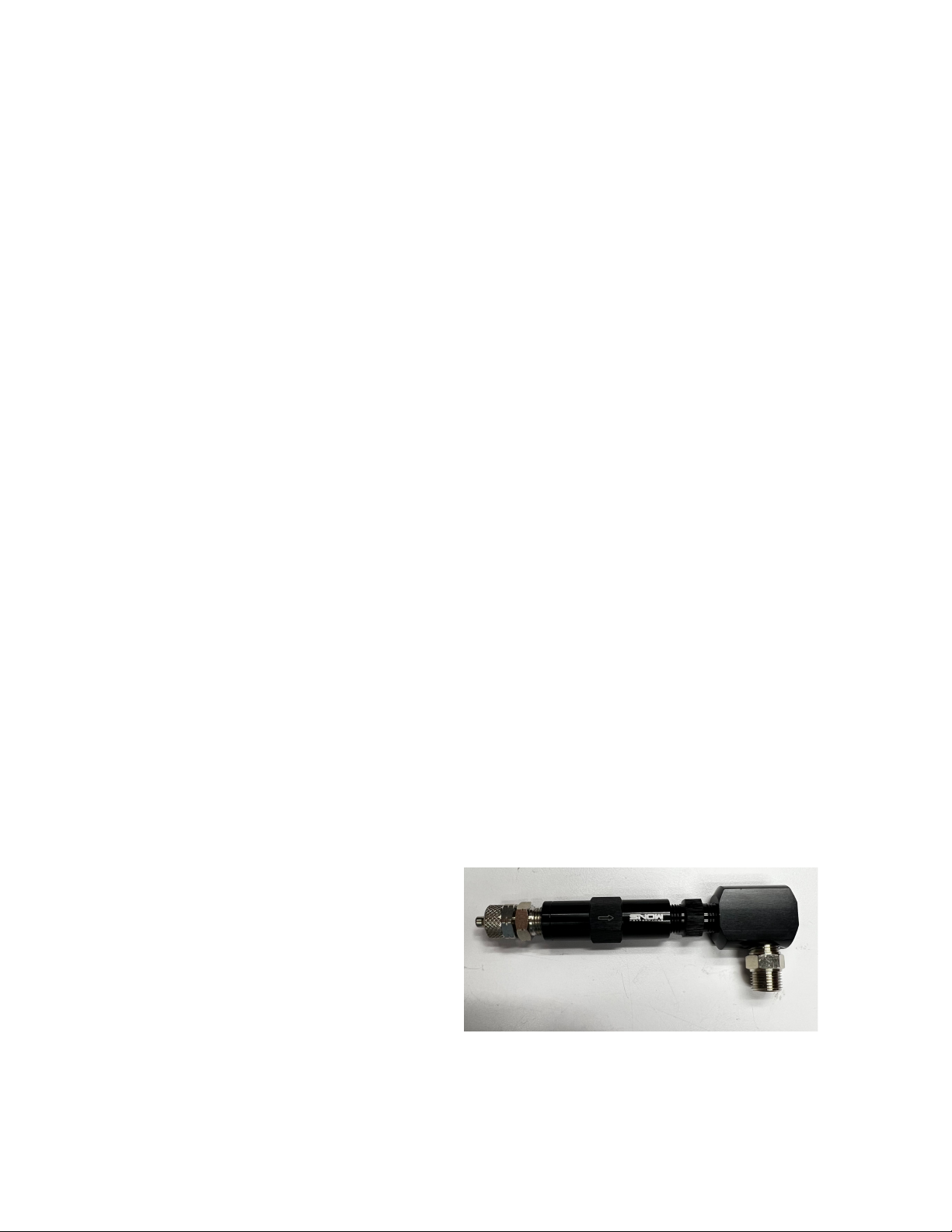
Step 6 High Flow Check Valve Install
The check valve assembly (35 PSI Crack Pressure) will ensure that boost pressure does not back-feed
air into the system or siphon due to engine vacuum. Ensure the check valve is installed with the arrow
pointing in the direction of flow. The Check valve may be installed anywhere between the pump and
nozzles. In a dual nozzle application the check valve will be placed between the pump and T fitting.
Quick Connect Kits Only- Fit the
NPT thread to push connect
adapters in both sides of the check
valve using E-6000 sealant on the
threads. Press the high pressure
tubing in each fitting, ensuring the
check valve is oriented properly in
the direction of flow.

Page | 7
Braided line kits - Fit the NPT thread to
4AN adapters in each side of the check
valve using E-6000 sealant on the NPT
threads only. Connect the 5 foot section of
braided line from the pump outlet to check
valve inlet and the 1’ or 2’ section of
braided line from the check valve outlet to
the nozzle holder inlet.
When running the high pressure tubing or braided line from the in line check valve to the nozzle holder
location, care should be taken to avoid extreme heat such as exhaust manifolds as well as any area
that may abrade the line due to engine vibration and torque over. Also, ensure the lines are clear of the
serpentine belt system.
Step 7 Electrical / Injection Settings
CAUTION: Disconnect the negative battery terminal while connecting wires to prevent electrical
fire or damage to controller.
To complete your water-meth install locate the part# for your injection kit and
follow the subsequent electrical wiring diagram/instructions. Thewires on the
level sensor / LEDs are interchangeable and itdoes not matter which wire
connects to ground or 12V source.
Mounting the MAP Sensor: When installing the MAP Sensor make sure itwill be
able to read a positive boost source from your vehicles forced induction application. Make
sure the wiring isran away from any hot engine parts. Also make sure the MAP Sensor is
secure and isunabletomove when the vehicle is moving.
Mounting: Mount the VC-30 controller in a dry location away from any moisture and engine heat.
Mount the display screen in a location that can be seen from the driver’s seat for access and viewing.
For any concerns please call our Tech service at phone number 940-767-7694.

Page | 8
Part #’s 20010/20010-BRD & 212/212-BRD
Wiring Diagram
Step 1 VC-30 Wiring/Boost Source
1. Plug your MAP Sensor/Controller connector into the VC-30.
2. Connect your MAP sensor to the wire strand with the (Green, White, Black) wires.
3. Connect your Controller to the wire strand with the (Green, Black, Red, Blue) wires.
4. Plug your (Red, White, Black) wire harness into the VC-30.
5. Connect the White wire from the wire harness to a 12V Switched Source. (Capable to additional 15amps)
6. Connect the Black wire from the wire harness to BATTERY Ground.
7. Connect the Black wire from the Pump to the BATTERY Ground.
Page | 9
Controller Operation
•Once the controller has 12V positive power it will turn on (We recommend to wire in your power source to a
switch so you have the ability to turn on/off your system at your own will.
•This controller is progress able to 30 PSI, but will operate at 100% after the 30 PSI.
•When changing your mode settings, to get back to the operation mode (where you can read your active
boost setting) just allow the controller to sit for 5 seconds and it will automatically go back to the operation
mode.
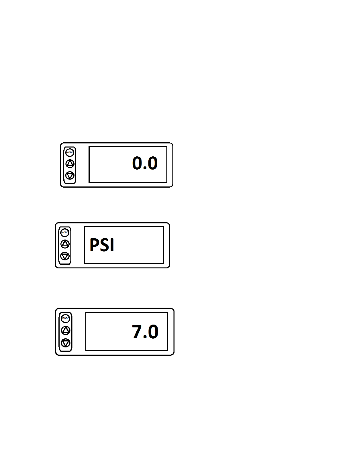
•You can press the MODE button to change the mode of the controller. (start screen)
•Press the MODE button once to change the display mode between PSI & BAR. Adjustments can be made
by pressing the up or down arrows.
•When you press the MODE button twice, the screen will change to the Minimum (Start) boost reference
screen. This is where you adjust the start of injection.

Page | 10
•When you press the MODE button three times the screen will change to your Max Boost reference screen.
At this boost level you will be injecting 100%. (Max is 30psi, anything above 30psi will continue at 100%)
•If you have any questions about your controller please feel free to contact our technical support at:
Tech@SnowPerformance.net
Tech Phone # 940-767-7694

Page | 11
Maintenance
Remove nozzle(s) and clean screen filters once per year using a calcium removing formula such as
CLR®
The Boost Cooler® has been designed to operate with high concentrations of methanol. Oil or other
additives are not required for system lubrication, and can cause damage to the system.
Contaminants in the fluid such as dirt can damage the system. Ensure that dirt and debris do not fall
into the tank. This can lead to solenoid/pump failure.
Do not use Teflon tape or paste to seal connections. These sealers are not as effective as the E-6000
sealant provided and can break down over time with high methanol use, clogging components.
Notes: The contents of this document are subject to change without prior notice. No part of or this entire document
may be reproduced in any form without prior written permission of Snow Performance, Inc. under the copyright
except for private use. The names, addresses and telephone numbers mentioned are current as of October 1,
2017. Note that this information is subject to change. Please refer to www.snowperformance.net for current
information.
Snow Performance 1-Year Warranty Policy:
Disclaimer
Do not use this product until you have carefully read the following agreement.
This sets forth the terms and conditions for the use of this product. The installation of this product indicates that the BUYER has
read and understands this agreement and accepts its terms and conditions. Performance products by their nature are designed to
increase horsepower and performance not engineered in the original vehicle and the increased stress could result in damage to
related systems. This is a high performance product – use at your own risk. Snow Performance Inc., Its agents, employees or
owners shall not be under any liability whether in contract or otherwise whether or not resulting from our negligence or contents of
information supplied for any damage or loss resulting from such information. The BUYER is responsible to fully understand the
capability and limitations of his/her vehicle according to manufacturer specifications and agrees to hold the SELLER harmless
from any damage resulting from failure to adhere to such specifications. The SELLER disclaims any warranty and expressly
disclaims any liability for personal injury or damages. The BUYER acknowledges and agrees that the disclaimer of any liability for
personal injury is a material term for this agreement and the BUYER agrees to indemnify the SELLER and to hold the SELLER
harmless from any claim related to the item of the equipment purchased. Under no circumstances will the SELLER be liable for
any damages or expenses by reason of use or sale of any such equipment. The BUYER is responsible to obey all applicable
federal, state, and local laws, statutes, and ordinances when operating his/her vehicle, and the BUYER agrees to hold SELLER
harmless from any violation thereof. The SELLER assumes no liability regarding the improper installation or misapplication of its
products. It is the installer's responsibility to check for proper installation and if in doubt, contact the manufacturer.

Page | 12
Snow Performance, Inc. warrants that the Product shall conform to and perform in accordance with published technical
specifications and shall be free of defects in materials and workmanship for 1-year providing:
1. You are the original purchaser and provide proof of purchase.
2. The system was purchased from a Snow Performance Authorized Dealer at MRP pricing set by SnowPerformance.*
*No warranty will be offered for any Snow Performance products if purchased below MRP. For MRP pricing of your
product check www.snowperformance.net.
3. An RMA # has been attained and is displayed on package containing returned part.
4. Parts Warranty ~ 90 day warranty on parts purchased separately if used in conjunction with a Snow System. No warranty
implied if used with a non-Snow part/system. Subject to Snow’s inspection of the product, Snow will remedy defects in materials
and/or workmanship by repairing or replacing, at Snow’s option, the defective product without charge for parts or labor, subject to
the limitations and exclusions described in this warranty.
This warranty does not cover problems caused by normal wear and tear including aesthetic oxidation of surfaces, accidents,
unlawful vehicle operation, or modifications or repairs to product not performed or authorized by Snow. This includes any product
that is disassembled or taken apart for any reason.
In addition, this warranty does not cover problems resulting from conditions beyond Snow’s control including, but not limited to,
theft, misuse, overloading, or failure to assemble, mount or use the product in accordance with Snow’s written instructions or
guidelines included with the
product or made available to the original retail purchaser. In the event of failure, Snow will repair or replace the part at Snow's
sole discretion. Failures resulting from misapplication or misuse of the Product, failure to adhere to any specifications or
instructions, or failure resulting from neglect, abuse, accidents, or act of nature are not covered under this warranty.
Warranty service may be obtained by emailing tech@snowperformance.net with a copy of your purchase invoice for the product,
getting an RMA (Return Merchandise Authorization) number, and delivering the part to Snow. Customer agrees to insure the
Product or assume the risk of loss or damage in transit, to prepay shipping charges to Snow, and to use the original shipping
container or equivalent. Shipping for Warranty replacement parts shipped outside the continental US will be charged to customer.
Non-Warranty Repair/Retest
Products returned due to damage or misuse and Products retested with no problem found are subject to repair/retest charges.
Product will be returned to customer at customer’s expense. A credit card number must be provided in order to obtain an RMA
(Return Merchandise Authorization) number prior to returning Product.
Distributor/Dealer Warranty:
All customers/dealers must deal directly with Snow Performance to receive warranty. No warranty will be issued through a
distributor for any reason.
Return Policy:
All returns must be called in for RMA #. Snow Performance will not take used kits or parts for refund. If you are returning an
unused kit there is a 15% restocking fee minus shipping/handling. All returns must be made within 30 days of purchase date. No
exceptions.
LIMITATION OF LIABILITY: REPAIR OR REPLACEMENT OF A DEFECTIVE PRODUCT IS THE ORIGINAL RETAIL
PURCHASER’S EXCLUSIVE REMEDY UNDER THIS WARRANTY. DAMAGE OR INJURY TO THE ORIGINAL RETAIL
PURCHASER, TO HIS OR HER VEHICLE, CARGO, OR PROPERTY, AND/OR TO ANY OTHER PERSON OR PROPERTY IS
NOT COVERED BY THIS WARRANTY. THIS WARRANTY IS EXPRESSLY MADE IN LIEU OF ANY AND ALL OTHER
EXPRESS WA RRANTIES, WHETHER ORAL OR WRITTEN. SNOW’S SOLE LIABILITY IS LIMITED TO THE REMEDY SET
FORTH ABOVE. IN NO EVENT WILL SNOW BE LIABLE FOR ANY DIRECT, INDIRECT, CONSEQUENTIAL, INCIDENTAL,
SPECIAL, EXEMPLARY, OR PUNITIVE DAMAGES OR FOR ANY OTHER DAMAGES OF ANY KIND OR NATURE
(INCLUDING, BUT NOT LIMITED TO, LOST PROFITS OR LOST SALES). SOME STATES DO NOT ALLOW THE EXCLUSION
OR LIMITATION OF INCIDENTAL OR CONSEQUENTIAL DAMAGES, SO THE ABOVE LIMITATIONS MAY NOT APPLY TO
YOU.
This manual suits for next models
3
Table of contents
Other Snow Performance Automobile Accessories manuals


