Matt:e ARD-1-32-TP-M User manual

ARD-1-32-TP-M
Installation Manual
V1.10 Mar 2022

2 | P a g e
Contents
Product Description 3
Warning Notice 3
Safety Advice 3
Introduction 4
Dimensions 5
Fixing Positions 6
Electrical Connections 7
Installation instructions 8
Operating Instructions 10
Test Function 10
Specifications 11
Warranty 11
Declaration of Conformity 12
PRODUCT ADVISORY NOTICE
This product must be installed by a competent person in
accordance with the IET Wiring Regulations, BS7671 (18th
Edition or later) and current Building Regulations.
Ensure the electrical supply is disconnected before installation
or removing the cover of the unit.

3 | P a g e
Product Description
The matt:eElectric Vehicle Charger Connection Units are designed for
use in commercial applications where 3 phase PME supplies are
feeding Electric Vehicle Chargers.
This manual covers the ARD-1-32-TP-M unit.
The unit is not intended for any purpose other than that defined within
this document.
WARNINGS
Please read and observe the following notices carefully. These
warnings must be observed when installing and operating the Electric
Vehicle Charger Connection Units.
All relevant supplies must be isolated or disconnected before commencing
any work. This product must be installed by a competent person in
accordance with the IET Wiring Regulations, BS7671 (18th Edition or later)
and any relevant Building Regulations and/or Installation Regulations.
Safety Advice
The unit must be installed in a dry ventilated location; it must never be
covered or have restricted ventilation.
The ARD-1-32-TP-M units are rated for a maximum 32A.
For any information not contained within this document, please contact our
technical support team on 01543 227290 or info@matt-e.co.uk.
Once installed, the unit has a Live Mains Supply (400v or higher)
within the enclosure. The cover must not be removed until the
supply to the unit has been isolated or disconnected.

4 | P a g e
Introduction
The matt:erange of Electric Vehicle Charger Connection Units are
fitted with O-PEN® technology designed to protect Electric Vehicle
Charging equipment when installed onto 3 phase PME infrastructures.
The unit incorporates a 5 pole isolator with a built-in under-voltage
release mechanism. On detection of fault conditions, the O-PEN®
electronic circuit de-energises the under-voltage release mechanism
which disconnects all poles of the supply including CPC.
The 5 pole isolator will automatically reset after a PEN fault, but must
be manually reset after an overcurrent fault in line with IET Wiring
Regulations and code of practice.
The matt:eO-PEN® technology does not require earth rods or
measuring electrodes to function correctly.
The units are designed to be installed indoors between the distribution
board and the Electric Vehicle Charger. The unit must be mounted
securely to a solid surface with the lid hinges on the left.
The installation location should be clean, dry and well ventilated.
Please refer to the diagrams on the following pages for the dimensions
and mounting arrangement of the unit.

5 | P a g e
Dimensions

6 | P a g e
Fixing Positions

7 | P a g e
Electrical Connections
The user wiring connections are indicated in the diagrams below.

8 | P a g e
Installation instructions
Connect the incoming cable from the distribution board directly to the
4-pole isolator. The CPC should be connected to the terminal block
Connect the outgoing cable(s) to the 4-pole MCB.
The outgoing CPC should be connected to the green isolated earth bar
THIS PRODUCT IS DESIGNED FOR AN ISOLATED
EARTHING ARRANGEMENT. CHECK BEFORE USING
SWA CABLE
On completion of installation the tightness of all electrical
connections should be checked before energising the unit.
See specifications for tightening torques.

9 | P a g e
Operating Instructions
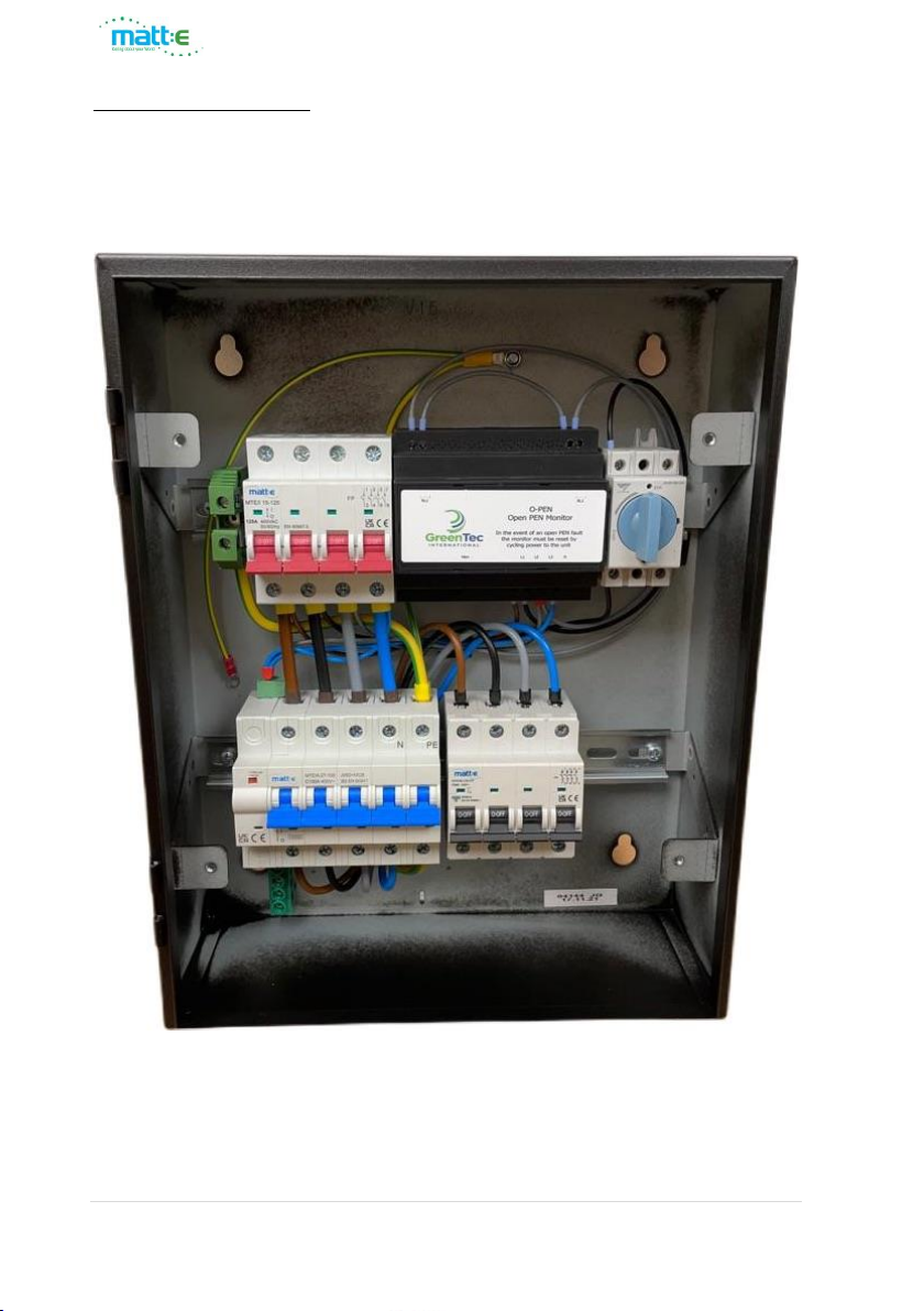
With the incoming isolator closed the unit will monitor the incoming
supply. If no fault condition is present approximately 1 second after
closing the incoming isolator the O-PEN monitor will energise the
under-voltage release mechanism of the 5 pole isolator (indicated by
the green LED illuminating). At this point the 5 pole isolator can be
closed to connect the load to the incoming supply. Alternatively wait
30 seconds and the isolator will automatically close.
In the event the O-PEN unit detects a fault condition on the monitored
supply for a period of 4 seconds the internal relays will de-energise and
remove the supply to the under-voltage release mechanism of the
5pole isolator. This will cause the 5 pole isolator to open disconnecting
all phases, neutral and CPC from the load.
Once the fault condition has cleared the O-PEN unit will reset after a 3
minute period and the 5 pole isolator will automatically reclose 30
seconds after
Test Function
A Test Switch is provided to allow the functionality of the
units to be checked. With the unit powered and the 5 pole
isolator closed rotate the Test Switch anti-clockwise to
position O to initiate a test. This will disconnect L1 from the O-PEN
monitor and create a fault condition. After 0.7 seconds the O-PEN
monitor will trip the 5 pole isolator by de-energising the under-voltage
release mechanism.
We recommend the unit is tested on a 6 monthly basis.

10 | P a g e
Specifications
Description
Electric Vehicle Charger Connection Unit
Input (Volts)
Nominal input voltage 400v, 50Hz, 3 Phase AC
Max Load
32A per phase
Dimensions
380mm x 300mm x 120mm
Weight
Approximately 7 kg
Operating Temp
-5°C to +40°C
Enclosure
Mild Steel Powder Coated
Power Consumption
12VA
Ingress Protection
IP4X
Document Revision
V1.10 Mar 2022
Terminal Capacities
Min
Max
Incoming Isolator cable size &
tightening torque
2.5 mm2
1.5Nm
25.0mm2
2Nm
Outgoing MCB cable size &
tightening torque
2.5 mm2
1.5Nm
25.0mm2
2Nm
Outgoing RCBO cable size &
tightening torque
2.5 mm2
1.5Nm
25.0mm2
2Nm
Warranty
The ARD-1-32-TP-M is guaranteed for a period of 1 year from the date of
manufacture.
This warranty is limited to the replacement of faulty components only.
t: 01543 227290 e: info@matt-e.co.uk w: www.matt-e.co.uk
matt:e Ltd, Unit 1 Langley Brook Business Park Middleton Tamworth BS78 2BP

11 | P a g e
EU Declaration of Conformity (DoC)
Ref: ARDCC-2022
We
Company name: matt:e Ltd
Postal address: Unit 1 Langley Brook Business Park
City Middleton, Tamworth
Postcode: B78 2BP
Telephone number: 01543-227290
Declare that this DoC is issued under the sole responsibility of the
manufacturer.
Apparatus model/Product: ARD-1-32-TP-M
Type: EVCC
Object of the declaration
Electric Vehicle Charger
Connection units
ARD-1-32-TP-M
The object of the declaration described above is in conformity with the relevant Union
harmonisation legislation:
Low Voltage Directive (2014/35/EU)
The following harmonised standards and technical specifications have been applied:
EN60255-1 2010 Emissions standard for Measuring Relays and Protection Equipment
EN55011 Class A 2011 + A1:2017 Emissions Standard for ISM Equipment
EN60255-26 2013 Immunity standard for Measuring Relays and Protection Equipment,
EN61000-4-2 2009 ESD Requirements
EN61000-4-3 2006 + A1 + A2 Radiated Susceptibility
EN61000-4-4 2012 Electrical Fast Transient Burst Requirement
EN61000-4-5 2006 Surges Requirements
EN61000-4-6 2009 Conducted Susceptibility
EN61000-4-11 2004 Voltage Dips and Interruptions
EN61439-1&2 2011 Low-voltage switchgear and control gear assemblies.
EN60947-3 Low-voltage switchgear and control gear
EN61095 Electromechanical contactors
EN61009-1 Residual current operated circuit-breakers with integral overcurrent
Signed for and on behalf of: matt:e Ltd
Place of issue Date J Charlton, Director
Tamworth, England March 2022
Table of contents
Other Matt:e Automobile Accessories manuals
Popular Automobile Accessories manuals by other brands

Westfalia
Westfalia 642579 instruction manual

Royal Rascals
Royal Rascals XLR-5 Installation instructions and tips

Prime Design
Prime Design VBR 326 manual

Ridewell Suspensions
Ridewell Suspensions RAR-240 owner's manual

Flash Cover
Flash Cover Slim MN009CT installation manual

FH Group
FH Group W-3 installation manual