Snow Performance 20130 User manual

© 2010, Snow Performance, Incorporated
INSTALLATION INSTRUCTIONS
FOR PART #20130 MUSTANG
STAGE 3 BOOST COOLER®
WATER/METHANOL INJECTION
SYSTEM

© 2010, Snow Performance, Inc
Contents:
Parts List...3
Introduction..4
Installation Mechanical.5
Installation Electrical...10
Controller Tuning.....11
Testing the S stem..16
Vehicle Tuning Quick Reference..17
Maintenance..18
Install Notes...21
Warrant .22
Contact Us..24
Have a question?
FAQ: www.snowperformance.net/faqs.php
CAUTION
You must completely read though these instructions before installing and
operating this product. ailure to due so can result in damage to this
product and the vehicle.

© 2010, Snow Performance, Inc
Parts List
o UHO (Ultra High
Output) Pump
o 10 ft. 1/4” OD Tubing
o 3ft. Black Wire Loom
o 18” 1/8” Silicone Tubing
o 3 Quart reservoir
Electrical Packet
o 2 Wire Splices
o 2 Butt Connectors
o Vacuum “T”
o 2 Small Eyehooks
o 1 emale Connector
o 1 Male Connector
o 10 Tie Wraps
o 3” Double Sided Tape
o Stage 3 Controller
o Level Switch Upgrade
Required tools
- Electric drill w/ drill bits
- Adjustable wrench
- Utility knife
- Screw driver – Phillips
- 5/16” open end wrench (for
nozzle)
-1/8” NPT Tap
Mechanical Packet
o 1 Nozzle Holder
o 8 #8x1&1/2in. Screws
o 8-#8 Washers
o 4 #6x1/2in. Screws
o 1 Tube E6000 GOOP®
o 1 Bulkhead itting
o 1 3/8 NPT to ¼” tube
reservoir fitting
Nozzles
o 60ML/MIN (1)
o 100ML/MN (2)
o 175ML/MN (3)
o 225ML/MN (4)
o 375ML/MN (5)
o 625ML/MN (6)
Upgrades
o 2.5 Gallon Reservoir
o Solenoid
o Hose Adaptor or Bung
o SafeInjection®
o Nitrobooster®
o Dual Nozzle
o Carb Plate

© 2010, Snow Performance, Inc
Introduction:
The Stage 3™ Mustang System is designed to deliver precise amounts
of water-methanol in a wide range of operating conditions. This system
can deliver cooler combustion temperatures, lower intake air
temperatures, and 20-25 point octane gains over regular pump gas. It
utilizes the factory washer fluid tank. This does not defeat the original
purpose of the tank and makes for an easy, professional installation.
Naturally aspirated Mustangs will utilize the E I sensor capability of the
controller for injection control, while Mustangs with forced induction of
any kind will use both boost and E I data to control injection.
Red to
switched
12V
2
1
Pump
Air
low
Throttle
P
late
Blue - To uel
Injector
Harness
Clear Boost Tube
White - To
Pump Red Wire
Turbo/
Supercharger/
Air ilter
actory Washer
luid Tank
Black
Black
Green Wire can
be tied out of
the way.
© 2010, Snow Performance, Inc
Contact Us:
Phone
Office (719) 633-3811
ax (719) 633-3496
Tech Support Line (Toll ree) (866) 365-2762
Web
http://www.snowperformance.net
Email
customerservice@snowperformance.net
Mail
Snow Performance, Inc
1017-A East Highway 24
Woodland Park, CO 80863
Notes
The contents of this document are subject to change without prior notice.
No part of or this entire document may be reproduced in any form
without prior written permission of Snow Performance, Inc under the
copyright except for private use.
The names, addresses and telephone numbers mentioned are current as
of January 1, 2009. Note that this information is subject to change.
Please refer to www.snowperformance.net for current information.

© 2010, Snow Performance, Inc
Products returned due to damage or misuse and Products retested with no problem found
will be returned to customer at customer’s expense.
LIMITATION O LIABILITY
REPAIR OR REPLACEMENT O A DE ECTIVE PRODUCT IS THE ORIGINAL RETAIL
PURCHASER’S EXCLUSIVE REMEDY UNDER THIS WARRANTY.
DAMAGE OR INJURY TO THE ORIGINAL RETAIL PURCHASER, TO HIS OR HER
VEHICLE, CARGO, OR PROPERTY, AND/OR TO ANY OTHER PERSON OR
PROPERTY IS NOT COVERED BY THIS WARRANTY.
THIS WARRANTY IS EXPRESSLY MADE IN LIEU O ANY AND ALL OTHER EXPRESS
WARRANTIES, WHETHER ORAL OR WRITTEN. SNOW’S SOLE LIABILITY IS LIMITED
TO THE REMEDY SET ORTH ABOVE. IN NO EVENT WILL SNOW BE LIABLE OR
ANY DIRECT, INDIRECT, CONSEQUENTIAL, INCIDENTAL, SPECIAL, EXEMPLARY, OR
PUNITIVE DAMAGES OR OR ANY OTHER DAMAGES O ANY KIND OR NATURE
(INCLUDING, BUT NOT LIMITED TO, LOST PRO ITS OR LOST SALES). SOME
STATES DO NOT ALLOW THE EXCLUSION OR LIMITATION O INCIDENTAL OR
CONSEQUENTIAL DAMAGES, SO THE ABOVE LIMITATIONS MAY NOT APPLY TO
YOU.
Non-Warranty Repair/Retest
Products returned due to damage or misuse and Products retested with no problem found
are subject to repair/retest charges. Product will be returned to customer at customer’s
expense. A credit card number must be provided in order to obtain an RMA (Return
Merchandise Authorization) number prior to returning Product.
© 2010, Snow Performance, Inc
Installation- Mechanical
Step 1 Bulkhead itting Install
The factory windshield washer
reservoir is used as the
reservoir for your system.
• Drill 9/16” hole in desired
bulkhead location.
• Remove one nut from
bulkhead and turn the
remaining nut until it is at the
very end.
• eed red tubing through the
drilled hole and up and out of
the top of the reservoir.
• Attach tubing to the bulkhead
on the side opposite the nut.
• Pull the tubing through the
bulkhead hole until the
bulkhead seats against the
inside of the reservoir.
• Apply E6000® sealant
(included) around bulkhead.
• Slide the nut you had
previously removed up onto
the tube and thread onto
bulkhead.
• While pulling firmly on the
red tubing, tighten the outer
nut using a 17mm socket
(only needs to be hand tight).
A ratchet is not needed.
• Once sealant has set, fill
reservoir with water and
check for leaks.
Factor washer tank from a 2007 GT shown with 9/16 hole drilled for
bulkhead fitting. See page 19 for details on mounting the optional
fluid level switch. Note that in some cases it will be easier to mount
the bulkhead fitting in the side of the tank so that the hose exits in
the direction of the pump.

© 2010, Snow Performance, Inc
Caution******
To avoid gravity feeding of fluid with rear mount reservoirs, it is essential
to use a check valve in-line between the reservoir and pump. Do not
operate your rear mount equipped vehicle without a check valve
installed.
Caution*******
Whenever the nozzle is mounted post-throttle plate, to avoid siphoning
fluid at idle, it is essential to use a solenoid upgrade inline between the
reservoir and pump.
Step 2 Pump Install
Mount the pump so the inlet is positioned at the lowest point of the
reservoir or lower. Pump can be mounted horizontally or vertically using
the supplied screws and washers. Ensure that no sharp bends in the
high pressure tube occur near the pump. Sharp bends can cause stress
on the inlet and outlet ports of the pump, causing leaks. Trim tube with a
utility knife or razor blade, making sure to eliminate any burrs or kinks on
the end. Insert firmly into the pump about ½ inch through the light grey
locking collar. Note the arrows indicating flow direction on the top of the
pump. To remove the hose, gently and evenly push the light grey locking
collar into the head unit of the pump, then pull on the hose gently.
© 2010, Snow Performance, Inc
Warrant
Warranty Policy
Snow Performance, Inc. warrants that the Product shall conform to and perform in
accordance with published technical specifications and shall be free of defects in materials
and workmanship for 90-days providing:
1. You are the original purchaser and provide proof of purchase.
2. or 1-year warranty, the Warranty Card that came with system (not applicable to
separate parts purchases) is returned to Snow within 45-days of purchase. If valid warranty
card not on file with Snow, the standard 90 day warranty applies from date of purchase.
3. or Lifetime warranty,
, the Warranty Card that came with system (not applicable to
separate parts purchases) is returned to Snow within 45-days of purchase and Boost
Juice® injection fluid is used exclusively.*
3. An RMA # has been attained and is displayed on package containing returned part.
4. Parts Warranty ~ 90 day warranty on parts purchased separately if used in conjunction
with a Snow System. No warranty implied if used with a non-Snow part/system.
Subject to Snow’s inspection of the product, Snow will remedy defects in materials and/or
workmanship by repairing or replacing, at Snow’s option, the defective product without
charge for parts or labor, subject to the limitations and exclusions described in this
warranty.
This warranty does not cover problems caused by normal wear and tear including aesthetic
oxidation of surfaces, accidents, unlawful vehicle operation, or modifications or repairs to
product not performed or authorized by Snow. This includes any product that is
disassembled or taken apart for any reason.
* Boost Juice® usage evidenced by invoices/ receipts.
In addition, this warranty does not cover problems resulting from conditions beyond Snow’s
control including, but not limited to, theft, misuse, overloading, or failure to assemble,
mount or use the product in accordance with Snow’s written instructions or guidelines
included with the product or made available to the original retail purchaser.
In the event of failure, Snow will repair or replace the part at Snow's sole discretion.
ailures resulting from misapplication or misuse of the Product, failure to adhere to any
specifications or instructions, or failure resulting from neglect, abuse, accidents, or act of
nature are not covered under this warranty.
Warranty service may be obtained by calling 719-633-3811, getting an RMA (Return
Merchandise Authorization), delivering the part to Snow along with proof of purchase.
Customer agrees to insure the Product or assume the risk of loss or damage in transit, to
prepay shipping charges to Snow, and to use the original shipping container or equivalent.
Shipping for Warranty replacement parts shipped outside the continental US will be
charged to customer.
Non-Warranty Repair/Retest

© 2010, Snow Performance, Inc
Install Notes
Pump Setting ____________(psi)
Nozzle Size ____________(ml/min)
Boost / Vacuum setting _________
Misc:
Disclaimer
Do not use this product until you have carefully read the following agreement.
This sets forth the terms and conditions for the use of this product. The installation of this
product indicates that the BUYER has read and understands this agreement and accepts
its terms and conditions.
Performance products by their nature are designed to increase horsepower and
performance not engineered in the original vehicle and the increased stress could result in
damage to related systems. This is a high performance product – use at your own risk.
Snow Performance Inc., Its agents, employees or owners shall not be under any liability
whether in contract or otherwise whether or not resulting from our negligence or contents of
information supplied for any damage or loss resulting from such information.
The BUYER is responsible to fully understand the capability and limitations of his/her
vehicle according to manufacturer specifications and agrees to hold the SELLER harmless
from any damage resulting from failure to adhere to such specifications.
The SELLER disclaims any warranty and expressly disclaims any liability for personal
injury or damages. The BUYER acknowledges and agrees that the disclaimer of any
liability for personal injury is a material term for this agreement and the BUYER agrees to
indemnify the SELLER and to hold the SELLER harmless from any claim related to the
item of the equipment purchased. Under no circumstances will the SELLER be liable for
any damages or expenses by reason of use or sale of any such equipment.
The BUYER is responsible to obey all applicable federal, state, and local laws, statutes,
and ordinances when operating his/her vehicle, and the BUYER agrees to hold SELLER
harmless from any violation thereof.
The SELLER assumes no liability regarding the improper installation or misapplication of its
products.
It is the installer's responsibility to check for proper installation and if in doubt, contact the
manufacturer.
© 2010, Snow Performance, Inc
Measure the distance from the bulkhead fitting on the reservoir to the
pump inlet. Cut the ¼” red tubing using utility knife. Make cuts are as
square as possible.
Ensure there are no kinks in the tubing and insert tubing into quick
disconnects at pump and reservoir until fully seated. Keep the pump
within 2 feet of the reservoir.
Caution******
Pump must be shielded from road debris and tire wash.
ailure to do so will result in pump failure
Step 3 Nozzle Selection
Nozzle sizing is a function of horsepower, which approximates the
engine airflow, and boost, which approximates intake charge heat. The
following are some general guidelines (assuming 50-50 water-methanol).
Engines running mild or high boost and making 400-600 HP will use a
375 ML/MN nozzle or 625 ML/MN nozzle. (Red and Blue colored nozzles
respectively)
Engines making mild boost and 200-400 HP will use a 175 ML/MN
nozzle or a 225 ML/MN nozzle.
A naturally aspirated engine making 300-400 HP will use a 100 ML/MN
nozzle or a 175 ML/MN nozzle.
A naturally aspirated engine making 400-600 HP will use a 225 ML/MN
nozzle or a 375 ML/MN nozzle.
Seal the nozzle into the nozzle holder using
included E6000® sealant. Using a sealant that is
not permanent will allow for nozzle changes during tuning. Simpl
remove the nozzle, clean the threads, and reinstall using sealant.
Assemble desired nozzle into nozzle holder using E6000® sealant. The
end of the nozzle with the fine mesh screen is to be inserted into
the nozzle holder. Torque 1/2 turn past finger tight. Do not use Teflon
sealants on Snow Performance fittings.

© 2010, Snow Performance, Inc
Correct Incorrect
Step 4 Nozzle Mounting
The nozzle should be installed 90° to the direction of airflow. On round
intake tubes, this is 360° around the tube meaning the nozzle can be
mounted in any direction. This will ensure maximum cooling as the
nozzle sprays in a cone pattern. The nozzle should be the highest point
in the system, and its tip should be flush with the inside wall of the tube
or projecting slightly into the airflow to ensure good spray pattern.
Drill and tap (11/32" pre-drill, 1/8”-27 NPT tap) air inlet tube as close as
feasible to throttle body/throttle plate. Be sure to remove the pipe to
avoid getting any shavings into the engine.
© 2010, Snow Performance, Inc
Solenoid Upgrade (optional)
The optional Solenoid Upgrade (#40060) is required if the nozzle is to be
installed after the intake throttle plate (as shown), or the fluid reservoir is
mounted higher then the nozzle. It is highly recommended for trunk-
mount reservoirs.
inger thread the two 1/8” NPT quick connect fittings into ports labeled (2
or IN) and (1 or OUT) on the solenoid. Tighten an additional half turn
past finger tight.
Note: Solenoid must be installed Pre-pump to ensure
correct operation.
Cut high pressure line at location solenoid is to be installed. Insert ends
of cut line into quick connect fittings of solenoid. The port labeled (2 or
IN) is the inlet and the port labeled (1 or OUT) is the outlet. Gently pull
on line to check secure connection. If line pulls out, re-insert farther into
fitting to engage locking clips. If high pressure line removal is required,
firmly press in metal fitting ring to disengage locking clips while pulling
hose from fitting.
Connect one of the BLACK wires from solenoid to the RED positive
pump wire or the WHITE wire from the controller. Note that connecting
the wire to any other power source other then the pump/controller wire
will result in improper operation of solenoid. Connect the second BLACK
wire to a secure chassis ground location.
White from S3
Harness

© 2010, Snow Performance, Inc
Fluid Level Switch
Fluid level switch and Bulkhead fitting shown on ’07 Mustang Washer Bottle.
Instructions
• Locate desired level switch mounting position. Suggested
placement is 1/5 of max reservoir height.
• Carefully drill side of reservoir using 13/16” bit. A step bit is
recommended for best drilling results. Hole
must be free of nicks or shavings for proper
sealing.
• Remove rubber seal from level switch.
Insert seal into reservoir until fully seated.
Goop can be used around the edges of the
hole.
• Lubricate exterior of level switch with water
and insert into seal until fully seated. Position level switch so GT
symbol is at six o’clock position.
• Wait 30 minutes for Goop to cure, then test for leaks. With fluid
level above level switch, float should be angled up. With fluid
level below level switch, float should be in horizontal position.
• Connect one black wire from level switch to ground.
• Connect other black wire from level switch to white wire from
LED.
• Connect red wire from LED to +12 volt key on power source.
© 2010, Snow Performance, Inc
Intake tube from Shelb GT shown. Note that the nozzle mount
adaptor (part number 40100) ma be useful for stock plastic intake
pipes.
The nozzle is mounted using its external 1/8 NPT threads. Tighten the
nozzle and nozzle holder assembly one half turn past finger tight using
E6000® sealant to seal the threads.
The recommended nozzle mounting point is before
the throttle bod /plate and above the level of the
reservoir. If ou mount the nozzle after the throttle bod /plate or
below the reservoir, a Solenoid Upgrade (#40060) must be used to
prevent siphoning at idle or gravit feed.

© 2010, Snow Performance, Inc
Step 5 Nozzle Connection
Measure the distance from the pump outlet to the nozzle holder(s). Cut
the ¼” tubing using a sharp utility knife or razor blade. Make cuts as
square as possible.
Ensure there are no kinks in the tubing and insert tubing into quick
disconnects until fully seated. Gently pull on tubing to ensure a good
connection. Also ensure that engine movement will not stress the tubing
or fittings.
Use tie wraps to help route tubing and to ensure it doesn't contact
moving or hot parts in the engine compartment. Have tubing connect to
quick connect fittings at shallow angles. Having an immediate sharp
bend may unseat the tubing from the internal o-ring and create a leak.
Continual insertion and removal from quick connect fittings will mar the
end of the tubing. Over time the internal gripping teeth may lose their
hold of the tubing which may create a leak. If this occurs simply remove
the tubing and make a fresh cut using a razor blade.
Installation – Electrical
Variable Controller Installation
© 2010, Snow Performance, Inc
For best performance, cooling and s stem life it is recommend that
Snow Performance Boost Juice™, part #40008, be the exclusive
fluid used in the s stem.

© 2010, Snow Performance, Inc
• The Pump should be off at this point. Start the vehicle and apply
pressure to the boost line with a hand pump. A few psig will be
sufficient to start injection. The controller should display an injection
% and a boost reading should also be visible (if you are in the proper
display screen).
• Ensure that the Blue leads are connected to a fuel injector harness.
Unit will show a PW value and also an injection % if you are in the
correct display mode with the vehicle idling. If no PW or injection is
indicated, check the connections to the fuel injector harness.
Tuning Quick Reference
The power potential of the s stem is realized through increased
boost and/or timing. The large gains on octane and cooling
provided b the s stem make this possible, even on standard pump
fuel.
The Boost Cooler® adds an alternate fuel source as well as
significantl cools combustion. With the Boost Cooler®, one does
not need to cool combustion with overl rich air/fuel ratios. To
minimize combustion quench, ou should start with an air to fuel
ratio of 12.0-12.5:1.
Injecting water/methanol lower than 3300-3500 RPM could result in
combustion quench. All vehicles are different. If the engine bogs or
loses power, then it is coming on too earl , the quantit is too
much, or there is not enough methanol in the mixture (50/50
water/methanol recommended).
Caution******
Prolonged quench ma cause lower engine damage over a period of
time.
Maintenance –
Remove nozzle(s) and clean screen filters at
least once per ear using carb cleaner.
The Boost Cooler® has been designed to operate with high
concentrations of methanol. Oil or other additives are not required
for s stem lubrication.
© 2010, Snow Performance, Inc
The Stage 3 controller has an integrated wiring harness for ease of
install and a clean appearance. Refer to the main wiring diagram and
listing below for installation.
CAUTION: Disconnect the negative batter terminal while
connecting wires to prevent electrical fire or damage to controller.
• Connect BLACK wire to a good ground location.
• Tie GREEN wire out of the way.
• Connect RED wire to a 12 volt key on source.
• Connect the two BLUE wires to the two wires leading to a fuel
injector using the provided wire splices. Any injector will suffice, so
choose one that is easy to access. Note: Do not solder electrical
connections to the fuel injector. Use provided wire splices.
• Connect the clear tubing to the black silicone line. This line can be
‘T’ed into any accurate manifold boost pressure source. A boost
gauge line that is tapped into the intake manifold is ideal. In naturally
aspirated applications, this can simply be tied out of the way.
• Connect the WHITE wire to the red power wire of the pump. The
BLACK wire on the pump goes to a good chassis ground.
Alwa s have a good electrical ground connection.
Poor ground will result in erratic operation of
controller and/or damage to the controller. Make
sure boost connection is POST throttle bod .
Tuning the Stage 3 System
The Stage 3 system allows for a large range of tuning on any E I or
forced induction Mustang. It can reference fuel injector pulse-width,
boost, or both simultaneously. The boost and E I data are displayed on
the LCD screen, along with the systems output as a percentage of pump
capability.
All functions of the controller are accessed using the two push buttons to
the left and right of the LCD screen. Pressing button 1 will scroll between

© 2010, Snow Performance, Inc
screens, while pressing button 2 will affect whatever setting is on the
screen.
Displa and Control Screens:
Screen 1
This is a display only screen. It displays boost, fuel injector pulse-width
(PW), and water/methanol injection as independent bar graphs.
Screen 2
This display screen shows boost in psi and injector pulse-width (PW) as
a percentage. 100% pulse-width indicated 100% injector duty cycle and
a fuel system injecting as much as possible
Screen 3
This screen displays boost in psi, while pulse-width (PW) and injection
are shown as a percentage.
Screen 4
This screen displays boost in psi and pulse-width (PW) as a percentage.
Screen 5
This is the first setup screen. It allows you to select BOOST, E I, or
BOTH, using button number two. If BOOST is selected, then boost alone
will determine the injection volume from the nozzle. If E I is selected,
then fuel injector pulse-width (PW) alone will determine injection volume.
If BOTH is selected then both inputs will be used simultaneously to
control injection.
Screen 6A
E I START INCREASE
This screen sets the injector PW point when injection will start through
the nozzle. Typical start points are in the 35% range.
B P
INJ
Boost PSI
EFI Pulse %
PSI %PW
% Injection
PSI
PW
Control = Both
Change
------------
EFI Start%
Increase--------------
© 2010, Snow Performance, Inc
• ill reservoir with water approx ¼ full.
• Remove tubing from nozzle (or solenoid if solenoid used in-line
between pump and nozzle) and run tube into separate container.
• Apply 12 VDC to red pump wire for approximately 5 seconds or
until fluid flow is consistent.
• Pump is now primed. Reconnect tubing from pump outlet to
nozzle (or solenoid).
If using a check valve in between the pump and the reservoir:
Remove the check valve and place a solid piece of tube between the
pump and the reservoir and prime the system. Then replace the check
valve in between the pump and reservoir.
Step 1 Test Pump and Mechanical System
Disconnect all control and SafeInjection® modules. Disconnect tube from
the outlet port of the pump. Using a 12 volt source, apply power to red
wire of pump. Pump should activate and fluid level in tank should go
down. It is recommended to also check the nozzle spray pattern while
following this procedure. Also check for leaks. Do not pump fluid through
a SafeInjection® module without all nozzles connected. This can
overflow the unit and cause damage.
If pump goes on and fluid level doesn't go down, there is an obstruction
in the tube or nozzle. Activation of the pump in 1-5 second intervals will
purge air from the system after installation. This can be accomplished
during initial use.
Step 2 Test Controller
• Turn ignition key on so that the system has 12volt power. If the
pump runs, inspect ground wires for secure connection and repair as
needed.
• Set the controller to inject at 1 psig of boost, and to start injection at
1% PW.

© 2010, Snow Performance, Inc
Boost Start: 4 psig
Boost ull: 15 psig
E I Start: 25%
E I ull: 65%
PW/BOOST 65/35
Under moderately heavy throttle, boost will trigger a small amount of
injection for cooling and efficiency. As more boost builds under higher
throttle positions, the system will add more injection. In the event that
boost reaches higher levels (such as in a race or in a WOT situation on
the street) the system will inject very aggressively for maximum octane
gain and cooling. But because E I data will provide a more gradual
injection curve (boost comes on instantly) the E I values are weighted
more heavily. This makes for a more progressive curve.
Note that in all of the above examples, all of the data needed in terms of
PW and boost can be obtained through the controller display itself.
Simply driving under cruising conditions and trying various levels of
throttle and boost will allow the user to determine good set points for
injection.
Other controller features:
The controller can be put into a “read-only mode” for the purpose of
viewing boost and E I data without injection. To toggle this mode on and
off, press and hold button 2 in any display screen. While holding button 2
down, press and hold button 1. After 1 second, release both buttons. The
controller will give no indication that it is in read only mode except for the
fact that it will not inject under any circumstances.
The controller also has the abilit to be programmed and displa
data in standard or metric units. Holding down button two while
powering up the unit will trigger metric units. Pressing and holding
button one as power is first applied will select standard units.
Testing the S stem
Note: for best results, prime pump before use
To clear air from the pump and insure that the system is primed:
© 2010, Snow Performance, Inc
Screen 6B
E I START DECREASE
This screen sets the injector PW when injection will start through the
nozzle.
Screen 6C
E I ULL INCREASE
This screen sets the fuel injector PW full point when maximum injection
through the nozzle will be reached. Typical E I full points are 60-80%.
Screen 6D
E I ULL DECREASE
This screen sets the fuel injector PW full point when maximum injection
through the nozzle will be reached.
Screen 7A
BOOST START INCREASE
This screen sets the boost pressure required to start injection through
the nozzle. This should be set at a boost that just above normal driving. If
you hit 5 psig leaving a stop light normally, set this to 7 psig.
Screen 7B
BOOST START DECREASE
This screen sets the boost required to start injection.
Screen 7C
BOOST ULL INCREASE
This screen sets the boost full point when maximum injection through the
nozzle will be reached. In most applications, this should be set at a boost
achieved at WOT in hard driving.
EFI Start%
Decrease
--
----------
-
EFI Full%
Increase
--
----------
EFI Full%
Decrease-------------
Boost Start
Increase
---------
Boost Start
Decrease-------------
Boost Full
Increase
--------------

© 2010, Snow Performance, Inc
Screen 7D
BOOST ULL DECREASE
This screen sets the boost full point when maximum injection through the
nozzle will be reached.
Screen 8A
PW/BOOST CONTROL INC
This screen adjusts the balance between boost and PW based injection.
Pressing button 2 will increase the PW importance and decrease the
boost importance by 1%. If it is set at 50/50, then PW and boost are
weighted equally to determine how much to inject at any given time. The
weighting can be adjusted in 1% increments. 50/50 is often a good
starting point.
Screen 8B
PW/BOOST CONTROL DEC
This screen will decrease the importance of PW while increasing the
importance of boost in 1% increments as you press button 2. Decreasing
the weight of boost is useful for quick spooling turbos or positive
displacement superchargers in E I applications. (See Screen 8A)
Screen 9
POWER MODE
Set this screen to Boost
Screen 10A/B/C/D
POWER set points
Set all POWER MODE points to 100. This mode is not used on a 20100
system and should be set such that POWER mode is not engaged.
20100 systems use the primary settings to control all injection.
Tuning Examples:
The following are some guidelines for common applications of the Stage
3 system on Mustangs. They are not meant to be strict rules. Each
application is different and will work best with different settings.
Naturall Aspirated EFI Mustang:
Boost Full
Decrease-------------
PW/Boost Control
5 /5 Inc-------
PW/Boost Control
5 /5
Dec
------
Power Mode Boost
Change
---------
Power Start 1
Increase
--------
---
© 2010, Snow Performance, Inc
Control injection through the E I function. This application idles at about
3% PW, cruises on level ground at 65 MPH at 15% PW, and will climb to
70% PW at WOT and peak RPMs:
Injection Mode: E I
E I Start: 20%
E I ull: 60%
Anytime any moderate throttle is applied, the system provides a small
amount of injection. As more throttle is applied and PW increases, the
system provides progressively more injection.
Moderate Boost EFI Application:
This car makes a peak boost of 12 psig with a Procharger, and at idle
has 5% PW, 65 MPH cruise is about 18%PW, and at WOT and peak
RPMs 85% PW:
Injection Modes: ‘BOTH’
E I Start: 40%
E I ull: 60%
Boost Start: 3 psig
Boost ull: 11psig
PW/BOOST 50/50
Here we are using both boost and PW to control injection. Procharger’s
have a smooth boost ramp that makes for a progressive injection curve.
So we weight boost and E I equally on screen 8. As boost and E I PW
go above normal cruising conditions, we get a small amount of injection.
In the event that high levels of throttle are used and boost goes to 9PSI,
the system will inject at full capacity.
Positive Displacement Blower Application:
This is a Whipple blower making about 15 psig. The blower makes
around 3 psig even in moderate throttle situations, and can hit 15 psig
almost instantly.
Injection Mode: ‘Both’
Other Snow Performance Other manuals
Popular Other manuals by other brands
AutoAqua
AutoAqua Smart AWC touch SAWC-200P manual

AquaCare
AquaCare TKF Series instruction manual
Aodyo Instruments
Aodyo Instruments Sylphyo Link user guide
Curt Manufacturing
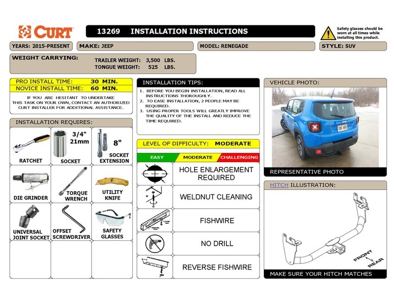
Curt Manufacturing 13269 installation instructions

F-SECURE
F-SECURE MOBILE SECURITY - QUICK GUIDE FOR BUSINESS Getting started

Arcam
Arcam ALPHA ONE manual
