2EN
1. DOCUMENTATION .............................................................3
2. DANGER AND WARNING .......................................................4
2.1. Risk of electrocution, burns or explosion ................................4
2.2. Risk of damaging the unit .............................................4
2.3. Liability .............................................................4
3. PRELIMINARY OPERATIONS....................................................5
4. INTRODUCTION ...............................................................6
4.1. Main functions .......................................................6
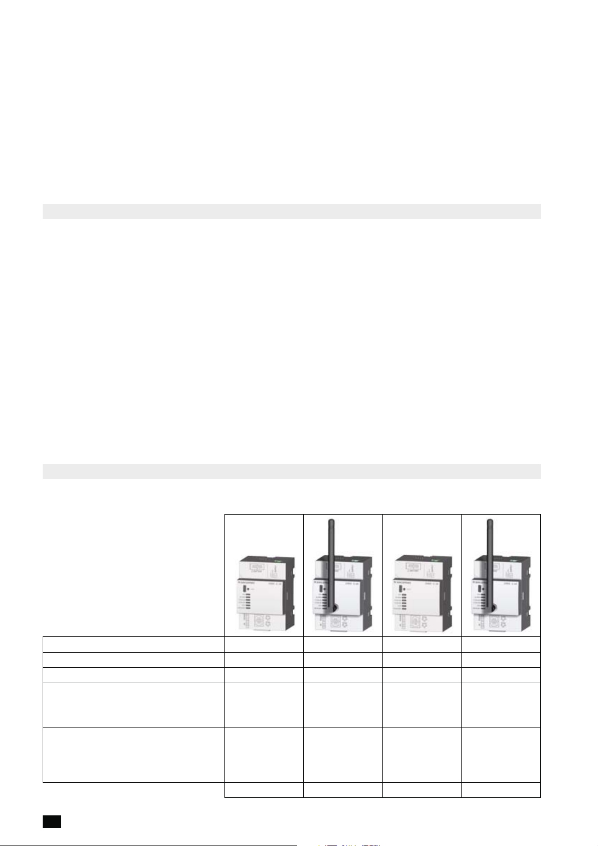
4.2. DIRIS G ............................................................6
4.2.1. Range ....................................................6
. . . . . . . . . . . . . . . . . . . . . . . . . . . . . . . . . . . . . . . . . . . . . . . .7
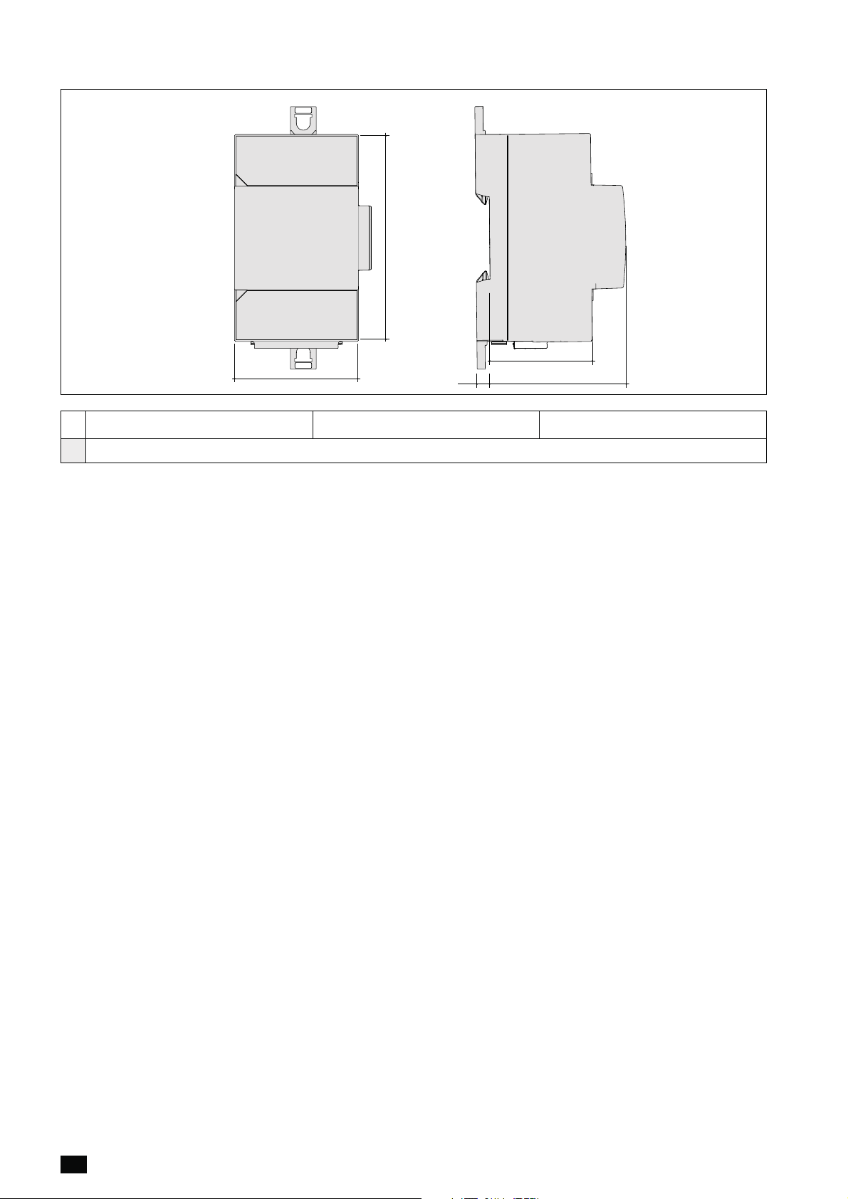
4.2.3. Dimensions ................................................7
4.3. Optional modules ....................................................7
4.3.1. Range ....................................................7
4.3.2. Dimensions ................................................8
5. INSTALLING A GATEWAY .......................................................9
5.1. Recommendations and safety .........................................9
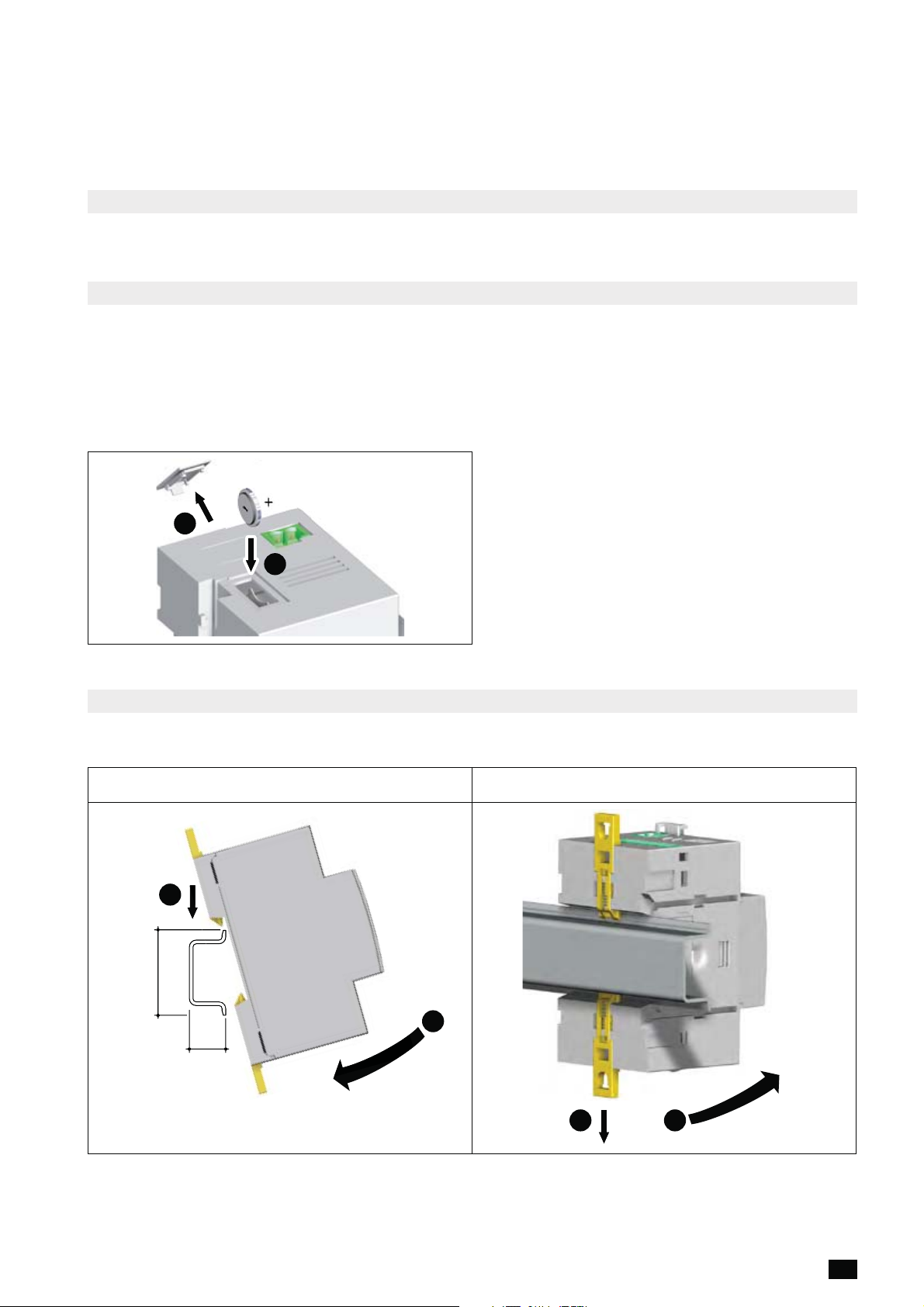
5.2. Fitting the battery ....................................................9
5.3. Installing a gateway ..................................................9
5.3.1. DIN rail mounting ...........................................9
5.3.2. Base-mounting............................................10
5.4. Installing the optional modules........................................10
5.4.1. Installing the optional module on the gateway ..................10
5.4.2. Installing an optional module on an optional module ............10
6. CONNECTION ................................................................11
6.1. Description of the terminals ..........................................11
6.2. Power supply connection ............................................12
6.3. Connecting the inputs ...............................................12
7. CONNECTING THE OPTIONAL MODULES ......................................13
7.1. Description of the terminals ..........................................13
......................................13
8. STATUS AND AUTO-ADDRESSING LEDS .......................................14
8.1. Status LEDs ........................................................14
8.2. Auto-addressing ....................................................15
9. COMMUNICATION ............................................................16
9.1. General information .................................................16
9.2. Communication with the products.....................................16
9.3. RS485 communication...............................................17
9.4. Radio-frequency (RF) communication..................................18
9.5. Multi-gateway communication ........................................19
9.6. Communication tables ...............................................19
10. CONFIGURATION ............................................................20
11. CHARACTERISTICS..........................................................21
EN CONTENTS