Sofamel HPN-130-H3 User manual
HPN-130-H3
Bedienungsanleitung
Manuale d’istruzione
Instruction manual
Instrucciones de uso
Instructions d’utilisation
C/ Thomas Alva Edison, 16-17 - Pol. Ind. Plans d’Arau
08787 La Pobla de Claramunt (Barcelona) - Spain
Tel. +34 938 087 980 - Fax +34 938 087 700

2
HPN-130-H3
Inhaltsangabe / Indice / Contents Seite / pagina / page
•Bedienungsanleitung
Hydraulische Handpresse – HPN-130-H3 .......................................................... 3
•Manuale d’istruzione
Utensile oleodinamico manuale per la compressione – HPN-130-H3 .............. 8
•
Instruction manual
Manual hydraulic compression tool – HPN-130-H3......................................... 13
•Instrucciones de uso
Prensahidráulica manual – HPN-130-H3 ...................................................... 18
•Instructions d’utilisation
Outillage hydraulique de compression – HPN-130-H3 ..................................... 23
DE
IT
EN
ES
FR

Bedienungsanleitung
Hydraulische Handpresse HPN-130-H3
3

4
HPN-130-H3
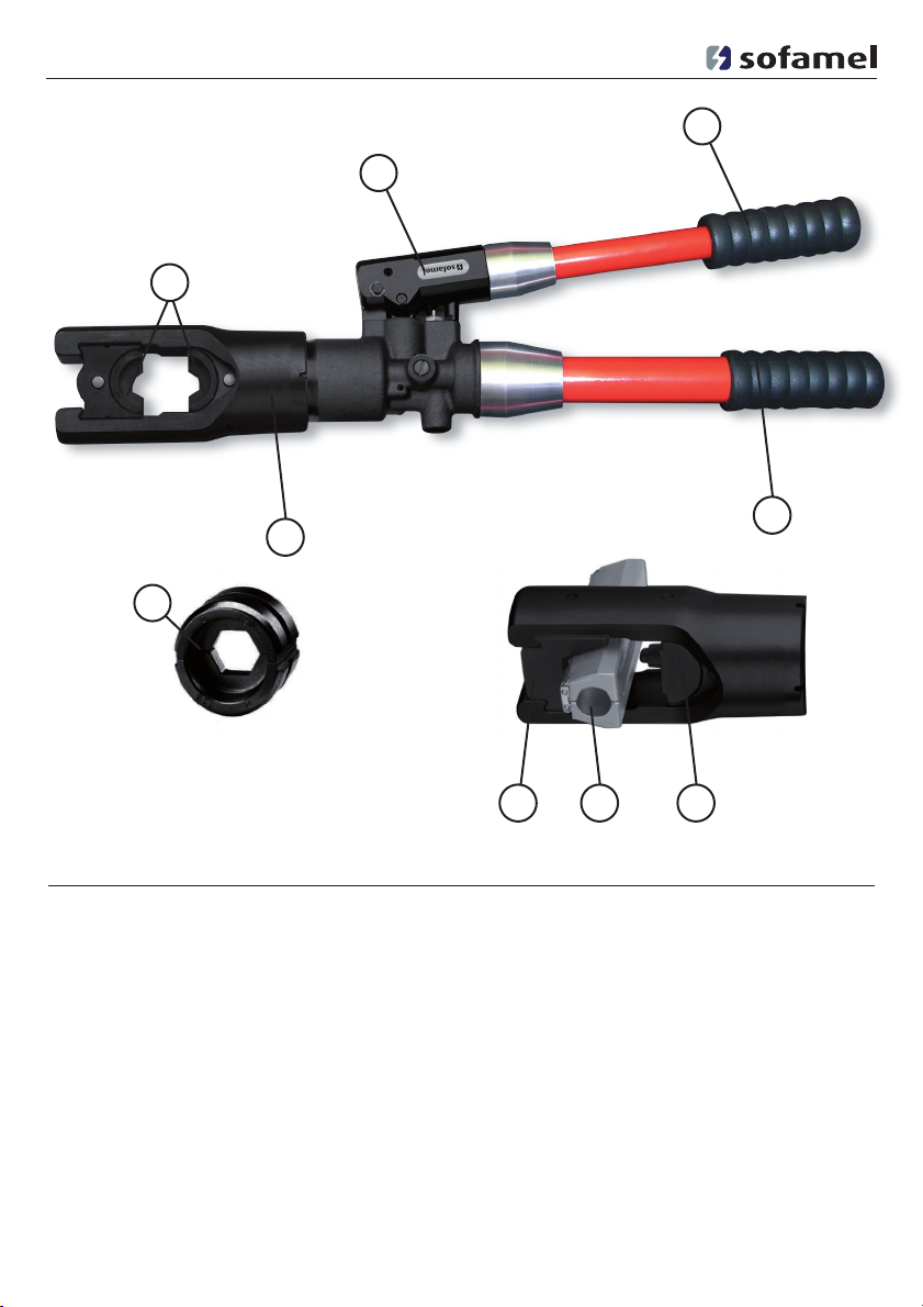
Pos.-Nr. Bezeichnung Funktion
1 Presseinsätze Halbschalen Presseinsätze mit unterschiedlichen
Pressprofilen
2 Presskopf 130 kN U–Presskopf für Presseinsätze (C–Schalen)
3 Pumphebel Hebel zur Durchführung des Pressvorganges
4 Griff Zum Führen des Werkzeuges
5 Druckablass Zurückstellen des Kolbens
6 Einsatzhalter Aufnahme der Halbschaleneinsätze
7 Adapter Zur Aufnahme von Tiefnutkäfig zur Tiefnutpressung
8 Tiefnutkäfig Zur Aufnahme des Verbindungsmaterials bei
Tiefnutpressung
9 Tiefnutdorn Pressdorn zur Erzeugung der Verpressung
6
2
3
5
4
1
8 97

5
HPN-130-H3
Inhaltsangabe Seite
1. Einleitung .............................................................................................................................5
2. Aufschriften .........................................................................................................................5
3. Gewährleistung ................................................................................................................... 5
4. Beschreibung der hydraulischen Handpresse.................................................................. 5
5. Hinweise zum bestimmungsgemäßen Gebrauch ........................................................... 5
5.1. Bedienung des Gerätes ...................................................................................................... 5
5.2. Erläuterung des Anwendungsbereiches .......................................................................... 6
5.3. Verarbeitungshinweise ...................................................................................................... 6
5.4. Wartungshinweise ..............................................................................................................6
5.5. Aufbewahrung und Transport des Preßgerätes ............................................................ 7
6. Verhalten bei Störungen am Preßgerät .......................................................................... 7
7. Außerbetriebnahme/Entsorgung ...................................................................................... 7
8. Technische Daten ................................................................................................................ 7
9. Legende ...............................................................................................................................7
1. Einleitung
2. Aufschriften
3. Gewährleistung
4. Beschreibung der hydraulischen
Handpresse
5. Hinweise zum bestimmungs
gemäßen Gebrauch
5.1. Bedienung des Gerätes
Achtung:
Preßwerkzeug niemals ohne
Preßeinsätze verwenden!
Vor Inbetriebnahme Ihres Preßgerätes lesen
Sie sich die Bedienungsanleitung sorgfältig
durch.
Benutzen Sie dieses Gerät ausschließlich für
den bestimmungsgemäßen Gebrauch.
Einbau und Montage von
Verbindungsmaterial mit Hilfe dieses
Werkzeuges darf nur durch eine elektro-
technisch unterwiesene Person erfolgen. Das
Mindestalter beträgt 16 Jahre.
Diese Bedienungsanleitung ist während der
gesamten Lebensdauer des Gerätes mitzu-
führen.
Der Betreiber muss
• dem Bediener die Betriebsanleitung
zugänglich machen und
• sich vergewissern, dass der Bediener sie
gelesen und verstanden hat.
Die Gewährleistung bei sachgemäßer Bedie-
nung beträgt 12 Monate ab Lieferdatum.
Das hydraulische Preßgerät mit unserer
Typbezeichnung HPN-130-H3 ist ein
handbe-tätigtes Gerät.
Als erstes wird für die gewünschte
Anwendung das geeignete Preßeinsatzpaar (1)
bereitgelegt.
Anschließend werden die Preßeinsätze nach-
einanderseitlich in die Einsatzhalter einge-
schoben bis sie mittig einrasten. Bei Tiefnut-
pressungen wird der Einsatzhalter (6)
Auf dem Pumpkörper finden Sie einen
Aufkleber mit der Typbezeichnung, der
Herstellerangabe, der Seriennummer und
technischen Daten.

seitlich aus dem Presskopf entfernt und statt
dessen der Adapter (7) mit Tiefnutkäfig (8)
eingeschoben. Auf der gegenüberliegenden
Seite muss der dazugehörige Tiefnutdorn
(9) in den Einsatzhalter eingesetzt werden.
Nachfolgend wird das Verbindungsmaterial
in den Presskopf eingelegt.
Der Pressvorgang wird gekennzeich-
net durch das Zusammenfahren der
Presseinsätze. Dabei befindet sich
das auf das Kabel aufgeschobene
Verbindungsmaterial bei geschlossenem
Presskopf in dem Pressprofil der stationä-
rem Hälfte des Presseinsatzes. Der auf der
Kolbenstange sitzende bewegliche Teil des
Presseinsatzes bewegt sich auf die Pressstelle
zu.
Das Werkzeug ist mit einem Doppelkolben
ausgestattet, der einen schnellen Vorschub
und einen langsamen Arbeitshub aufweist.
Im Niederdruckbereich wird beim Schließen
des Pumphebels (3) der schnelle Vorschub
realisiert. Im Hochdruckbereich wird eben-
falls beim Schließen ein Kolbenvorschub
bewirkt.
Ein Pressvorgang ist abgeschlossen, wenn die
Werkzeugeinsätze vollständig zusammen-
gefahren sind und die maximale Presskraft
erreicht wurde. Dieses wird durch ein spür-
bares Nachlassen der Handkraft angezeigt.
Nach vollendeter Pressung wird durch
Drehen und gleichzeitiges Schließen des
Pumphebels (3) der Rücklauf des Kolbens
ausgelöst. Im Fehlerfall kann in jeder
Position der Kolben zurückgefahren werden.
Anschließend kann entweder ein weiterer
Pressvorgang vorgenommen werden oder
das Verbindungsmaterial aus dem Presskopf
(2) herausgenommen werden. Nach Beeend-
igung der Pressvorgänge muss die Verriegel-
ung (5) durch Schließen des Pumphebels (3)
mit anschließendem Drehen nach links (bis
zur 2. Arretierung).
Das Pressgerät verfügt über eine große
Anzahl verschiedener Presseinsätze (1) zum
Verpressen von Cu– und Al–Verbindungs-
material.
Den Einsatzbereich der verschiedenen
Presseinsätze entnehmen Sie bitte den ent-
sprechenden Presseinsatztabellen.
Sollten andere Verbindungsmaterialien ver-
presst werden müssen, ist eine Rücksprache
mit dem Werk zwingend erforderlich.
Vor Arbeitsbeginnist zwingend ein span-
nungsfreier Zustand der zu verpressenden
Verbindung sicherzustellen.
5.3. Verarbeitungshinweise
Trotz gleicher Kennzahl sind die Pressbreiten
bei Cu- und Al-Presskabelschuhen und
Verbindern unterschiedlich.
6
HPN-130-H3
5.2. Erläuterung des
Anwendungsbereiches
Achtung:
Es dürfen keine unter Spannung
stehenden Teile verpresst wer-
den.
5.4. Wartungshinweise
Das hydraulische Pressgerät ist nach jedem
Gebrauch zu reinigen und ein trockener
Zustand vor Einlagerung sicherzustellen. Das
Gerät ist im Prinzip wartungsfrei, lediglich
die Bolzenverbindungen am Pumphebel sind
leicht einzuölen.
Wir empfehlen, das Gerät nach Ablauf eines
Jahres zur Durchsicht ins Lieferwerk einzu-
schicken.
Achtung: Es dürfen auch bei
gleicher Kennzahl nur die für
das Material vorgesehenen
Presseinsätze verwendet werden.

Die Entsorgung der einzelnen Komponenten
des Aggregates muss getrennt erfolgen.
Dabei muss zuerst das Öl abgelassen werden
und an speziellen Abnahmestellen entsorgt
werden.
Die restlichen Teile des Aggregates müssen
nach den jeweils gültigen Umweltstandards
entsorgt werden. Wir empfehlen wegen
möglicher Umweltverschmutzung die
Entsorgung durch zugelassene Fachunter-
nehmen vornehmen zu lassen. Eine kosten-
freie Rücknahme des Altgerätes durch den
Hersteller kann nicht zugesagt werden.
Presskopf im drucklosen Zustand 270° drehbar
Gewicht: ........................................................................................................................ca. 6,2 kg
Presskraft: ..........................................................................................................................130 kN
Tankvolumen: ............................................................................................................ca. 120 ml
Hydrauliköl:..............................................................................................Shell naturelle HF - E15
Einsatztemperatur: .............................................................................................-20°C bis +50°C
Kolbenhub: ........................................................................................................................30 mm
Maße:................................................................................................................. 564x174x70 mm
a) Die Presseinsätze (1) bleiben während des
Pumpvorganges stehen, bzw. das
Werkzeug löst bei Enddruck nicht aus.
=> Das Gerät einschicken.
b) Das Presswerkzeug verliert Öl.
=> Das Gerät einschicken
Nicht ohne
Presseinsätze
betätigen
Achtung! Vor Gebrauch
Bedienungsan-
leitung lesen
HPN-130-H3
5.5. Aufbewahrung und Transport des
Pressgerätes
Um das Pressgerät vor Beschädigungen
zu schützen, muss es nach Gebrauch und
nachdem es gesäubert worden ist, in den
optional erhältlichen Transportkoffer gelegt
werden, der dann anschließend sicher zu
verschließen ist.
In diesem Koffer (optional erhältlich) fin-
den zusätzlich 11 Presseinsatzpaare und die
Gebrauchsanweisung Platz.
7
8. Technische Daten
9. Legende
6. Verhalten bei Störungen am
Pressgerät
7. Außerbetriebnahme/Entsorgung
Achtung: Hydrauliköle stellen
eine Gefahr für das Grundwasser
dar. Unkontrolliertes
Ablassen oder unsachgemäße
Entsorgung steht unter Strafe.
(Umwelthaftungsgesetz)
103451

Manuale d’uso
Utensile oleodinamico manuale per
la compressione – HPN-130-H3
8
9
HPN-130-H3
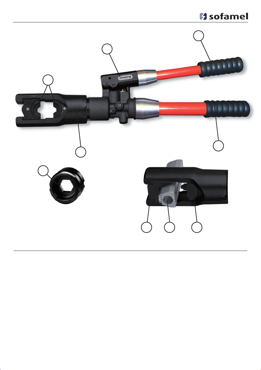
Pos. n° Denominazione Funzione
1 Matrici matrici con diversi profili di compressione
2 Testa testa a C, 130 kN per matrici larghe
3 Leva della pompa leva per eseguire il ciclo lavorativo
4 Manico per maneggiare l’utensile
5 Rilascio rilascio del pistone di lavoro
6 Supporto matrici Supporto che sostiene le matrici (semicuscinetti)
7 Adattore per il supporto della gabbia per la compressione
scanalatura profonda
8 Gabbia da scanalatura prof. Per mantenere il materiale da aggraffare durante
la compressione a scanalatura profonda
9 Mandrino da scanal. prof. mandrino da compressione
6
2
3
5
4
1
8 97

10
HPN-130-H3
Indice Pagina
1. Introduzione
2. Etichette
3. Garanzia
4. Descrizione dell’utensile per la
compressione idraulico
5. Indicazioni per l’uso corretto
(secondo le disposizioni)
5.1. Uso dell’utensile
Attenzione:
Non utilizzate mai l’utensile da
compressione senza matrici!
Prima della messa in servizio dell’ utensile
oleodinamico per la compressione, Vi pre-
ghiamo di leggere attentamente le istruzioni
per l’uso.
Siete inoltre pregati di impiegare l’utensile
soltanto per l’uso per il quale è stato conce-
pito.
Il montaggio di materiale da collegamento
che viene fatto con questoutensile può esse-
re effettuato esclusivamente da unapersona
a conoscenza delle rispettive istruzioni elett-
rotecniche. L’età minima è di 16 anni.
Le istruzioni per l’uso devono sempre
essere allegate all’utensile.
Il gestore ha il dovere di
• Fornire le istruzioni per l’uso all’operatore
• Assicurarsi che l’operatore le abbia
lette e comprese
1. Introduzione......................................................................................................................10
2. Etichette ...........................................................................................................................10
3. Garanzia............................................................................................................................10
4. Descrizione dell’utensile oleodinamico per la compressione ..........................................10
5. Indicazioni per l’uso corretto (secondo le disposizioni)....................................................10
5.1. Uso dell’utensile ..............................................................................................................10
5.2. Descrizione del campo d’applicazione ............................................................................11
5.3. Indicazioni per l’uso ..........................................................................................................11
5.4. Indicazioni per la manutenzione .......................................................................................11
5.5. Immagazzinamento e trasporto dell’utensile da compressione........................................12
6. Comportamento in caso di guasto all’utensile ...............................................................12
7. Messa fuori servizio/smaltimento......................................................................................12
8. Dati tecnici .......................................................................................................................12
9. Legenda ...........................................................................................................................12
Nel casodi corretto uso e di osservanza dei
controlli regolari, la garanzia è di 12 mesi a
partire dalla data di consegna.
L’utensile oleodinamico per la compressione
HPN-130-H3 è un’utensile ad azionamento
manuale.
In primo luogo viene preparata la coppia di
matrici adatti (1) al processo lavorativo.
Di seguito, le matrici di compressione ven-
gono inserite lateralmente nel supporto
matrici, una dopo l’altra, nella testa della
pressa fino all’arresto a scatto centrato.
Sulla pompa si trova un’etichetta autoadesi-
va che riporta il modello, la ditta produttri-
ce, il numero di serie ed i dati tecnici.

In caso di compressione a scanalatura pro-
fonda, sfilare lateralmente il supporto delle
matrici (6) dalla testa oleodinamica e sosti-
tuirlo con l’adattatore (7) con gabbia per
scanalatura profonda (8). Sul lato opposto
inserire quindi nel supporto matrici il relativo
mandrino (9). A questo punto posizionare il
materiale da aggraffare nella testa oleodi-
namica.
Il processo di compressione è caratterizzato
dall’avvicinarsi degli inserti da compressione.
Il materiale da collegare, posto su un con-
duttore, si trova dalla parte fissa dell’inserto
di compressione quando la testa dell’utensile
è chiusa. La parte scorrevole dell’inserto da
compressione è fissata sull’asta dello stan-
tuffo. Questa parte scorrevole si avvicina al
materiale da pressare.
L’utensile è dotato di una pompa a due
velocità, la quale consente un avanzamento
rapido ed una corsa utile lenta. Lavorando a
bassa pressione, l’avanzamento rapido viene
realizzato chiudendo la leva della pompa (3).
In condizioni di pressione elevata, la chiusura
provoca un avanzamento del pistone.
Un processo di compressione è concluso
quando le due matrici si sono avvicinate il
più possibile e quando la forza massima è
stata raggiunta. Questo stato viene segna-
lato da una forte diminuzione della forza
nella mano. Al termine del ciclo di compres-
sione, ruotare la leva della pompa (3) e chi-
uderla per avviare il ritorno dello stantuffo.
In caso di guasti, lo stantuffo può essere
riportato nella posizione di partenza in ogni
fase di lavoro.
Di seguito è possibile avviare un ulteriore
ciclo di lavoro oppure rimuovere il materiale
di connessione dalla testa della pressa (2). Al
termine del processo di compressione, atti-
vare nuovamente l’arresto (5) tramite la chi-
usura della leva della pompa (3), ruotandola
a sinistra fino al secondo arresto.
L’utensile per la compressione dispone di un
gran numero di matrici (1) di diverso tipo
per la pressatura di materiale di connessione
in alluminio e in rame.
Nel caso di compressione di altri materiali, è
assolutamente necessario consultarsi con lo
stabilimento.
Prima di avviare il processo lavorativo, il
materiale da comprimere deve essere privo
di tensione.
5.3. Indicazioni per l’uso
Nonostante che abbiano gli stessi indici, le
larghezze di compressione dei capocorda e
dei connettori di rame e di alluminio non
sono uguali.
11
HPN-130-H3
5.2. Descrizione del campo
d’applicazione
Attenzione:
Parti sotto tensione non possono
mai essere pressate.
5.4. Indicazioni per la manutenzione
L’utensile oleodinamico per la compressione
va pulito ed asciugato dopo ogni utilizzo e
prima di essere immagazzinato.
Non richiede alcuna manutenzione, soltanto
il collegamento della leva della pompa va
lubrificato di tanto in tanto.
Consigliamo inoltre di inviare l’utensile allo
stabilimento fornitore dopo un anno opera-
tivo per effettuare un controllo.
Attenzione: Anche in caso di
indici uguali, vanno utilizzati
esclusivamente le matrici previste
per il rispettivo materiale.

Lo smaltimento dei singoli componenti deve
avvenire separatamente. Prima deve essere
scaricato l’olio, il quale di seguito va smaltito
presso punti di raccolta autorizzati.
Le restanti parti dell’apparecchio devono
essere smaltite secondo i vigenti standard
ambientali.
Suggeriamo, per evitare un possibile inqui-
namento ambientale, di affidare lo smalti-
mento a ditte autorizzate. Non è assicurato
il ritiro gratuito del vecchio apparecchio da
parte del produttore.
Testa oleodinamica girevole (270°) a pressione zero.
Peso:..............................................................................................................................ca. 6,2 kg
Forza massima: .................................................................................................................130 kN
Volume del serbatoio: ..................................................................................................ca. 120 ml
Olio oleodinamico: ..................................................................................Shell naturelle HF - E15
Temperatura d’impiego: .................................................................................-20°C fino a +50°C
Corsa mass.: .....................................................................................................................30 mm
Dimensioni: ........................................................................................................564x174x70 mm
non ritorna.
=> Inviare l’utensile.
b) L’utensile oleodinamico per la compres-
sione perde olio.
=> Inviare l’utensile.
Non usare
senza matrici Attenzione!
Pericolo di
schiacciamento
Prima dell’uso
leggere le
istruzioni d’uso
12
8. Dati tecnici
9. Leggenda
HPN-130-H3
5.5. Immagazzinamento e trasporto
Per proteggere l’utensile da eventuali
danneggiamenti, consigliamo di rimetterlo
nella valigietta dopo l’uso e dopo averlo
pulito. Di seguito,richiudere accuratamente
la valigetta. In questa valigia vi é spazio
anche per 11 matrici e per l’istruzione manu-
ale.
6. Comportamento in caso di guasto
a) le matrici (1) si fermano durante il proces-
so oppure l’utensile, a pressione finale,
7. Messa fuori servizio/
smaltimento
Attenzione: Gli oli idraulici
rappresentano un pericolo per
l’acqua di falda. Uno scarico non
controllato dell’olio o un suo
irregolare smaltimento sono
soggetti a punizioni secondo la
legge sulle responsabilità ambien-
tali.
103451

13
Instruction manual
Manual hydraulic compression
tool – HPN-130-H3

14
HPN-130-H3
Item no. Description Function
1 Dies interchangeable shell crimping dies
2 Crimping head 130 kN U-shaped head for wide crimping dies
3 Pump lever lever to carry out the crimping process
4 Guiding handle handle to guide and position the tool
5 Pressure release piston return
6 Die holder holds the upper die
7 Adaptor to support the cage for deep notch for the deep
notch crimping
8 Cage for deep notch to support the coupling material for the deep
notch crimping
9 Arbor to produce the crimping process
6
2
3
5
4
1
8 97

15
HPN-130-H3
Contents Page
1. Introduction
2. Labels
3. Warranty
4. Description of the manual hydraulic
compression tool
Caution:
Do not operate the compression
tool without dies.
Before putting into operation your compres-
sion tool please read the operating instruc-
tions carefully.
Use this tool exclusively in the field of
application it is designed for.
Only specially trained persons are allowed
to mount and assemble connectors with the
help of this tool. The minimum age is 16
years.
The operating instructions have to be carried
along during the entire life span of the tool.
The operator has to
• ensure that the operating instructions are
available for the user
• make sure that the user has read and
understood the operating instructions.
1. Introduction .....................................................................................................................15
2. Labels...............................................................................................................................15
3. Warranty...........................................................................................................................15
4. Description of the manual hydraulic compression tool....................................................15
5. Instructions for proper use ...............................................................................................15
5.1. Operation of the tool ........................................................................................................15
5.2. Explanation of the application range................................................................................16
5.3. Mounting instructions.......................................................................................................16
5.4. Service and maintenance instructions .............................................................................16
5.5. Storage and transport of the compression tool...............................................................16
6. Troubleshooting................................................................................................................17
7. Putting out of service / disposal.......................................................................................17
8. Specifications...................................................................................................................17
9. Legend.............................................................................................................................17
Subject to proper use we grant a warranty
period of 12 months from the date of delivery.
The manual hydraulic compression tool
HPN-130-H3 is a handtool.
5. Instructions for proper use
5.1. Operation of the tool
First select the appropriate pair of dies (1)
for the intended application.
After that, insert the compression dies one
after the other sideways into the die holders
until they engage centrally. For deep notch
compression remove the die holder (6) side-
ways from the comression head and insert
the adaptor (7) with the cage for deep
notch (8). On the opposite side insert arbor
(9) into the die holder (6). Then the connec-
tor is inserted into the crimping head.
On the pump you find a label with the type
designation, the name of the manufacturer,
the serial number and the specifications.

A crimping process is started by performing
pumping movements with the pump lever
(3).
During the compression process the dies
approach each other. With closed compres-
sion head the connector on the conductor is
located in the stationary half of the dies. The
moving part, which is located on the piston
rod, approaches the compression point.
The tool is equipped with a double piston
which is characterized by quick feed and a
slow working stroke. Under low pressure the
pump lever (3) is closed in quick feed mode.
Under high pressure the piston moves forward
when the pump lever is closed.
A compression process is terminated when
the dies have closed completely and the
maximum compression force has been
reached. This is indicated by a significant
decrease in the manual force.
After the compression process turn and close
the pump lever (3) to trigger the return of
the piston. In case of malfunction the piston
can be returned in any position.
After that, a further compression process can
be started or the connector can be removed
from the compression head (2). After the
compression processes the locking device
(5) has to be activated by closing the pump
lever (3) and turning it to the left (to the
second catch).
The compression tool is equipped with a
large number of different dies (item no. 1)
for compression copper and aluminium con-
nectors.
In case you want to crimp different connec-
tors, it is absolutely necessary to consult the
manufacturer.
Before starting the compression process
make sure that the connector to be crimped
is voltageless.
5.3. Mounting instructions
In spite of the same code numbers the com-
pression width for copper and aluminium
cable lugs and connectors is not the same.
16
HPN-130-H3
5.2. Explanation of the application
range
Caution:
Do not crimp live parts.
5.4. Service and maintenance instructions
Make sure that the hydraulic compression
tool is cleaned and dried after every use
before it is stored. Basically, the tool is main-
tenance-free, merely the bolt fastenings at
the pump lever have to be slightly oiled.
We recommend having the tool checked by
the manufacturer after one year.
5.5 Storage and transport of the
compression tool
In order to protect the compression tool
from damage it has to be placed into the
transportation case after use and careful
cleaning. The case has to be locked safely.
Into this case you can put 11 dies and the
instruction manual.
Caution:
Even if the code number is identical,
use only those dies which
are suitable for the material.

The various components of the tool have to
be disposed of separately. First drain the oil
and take it to a special disposal point.
For the disposal of the remaining parts of the
tool please observe the valid environment
regulations.
To avoid damage to the environment we
recommend that authorized professional
companies dispose of the tool. The
manufacturer can not take back the tool
free of charge.
In the absence of pressure the crimping head can be turned 270°.
Weight: ..................................................................................................................approx. 6,2 kg
Crimping force: .................................................................................................................130 kN
Tank volume: ................................................................................................................ca. 120 cl
Hydraulic oil: ...........................................................................................Shell naturelle HF - E15
Use temperature: .................................................................................................-20°C to +50°C
Piston stroke: ....................................................................................................................30 mm
Dimensions: .......................................................................................................564x174x70 mm
a) The dies (1) stop during the compression
process or the tool does not reach the
final pressure.
=> Return the tool to the manufacturer.
b) The tool loses oil.
=> Return the tool to the manufacturer.
Never use
without dies Caution!
Risk of
crushing
Read the instruction
manual befor use
HPN-130-H3
17
8. Specifications
9. Legend
6. Troubleshooting
7. Putting out of service / disposal
Caution: Hydraulic oils represent
a danger for the ground water.
Uncontrolled draining or improper
disposal are punishable
(Environment Liability Law).
103451
18
Instrucciones de uso
Prensa hidráulica manual – HPN-130-H3
19
HPN-130-H3
N° ref. Descripción Función
1 Matrices matrices con perfiles diferentes
2 Cabeza cabeza en U, 130 kN para moldes anchos
3 Palanca de la bomba para la ejecución del ciclo de trabajo
4 Empuñadura para manejar la herramienta
5 Lanzamiento lanzamiento del pistón del trabajo
6 Soporte de los moldes soporte que sostiene los moldes (semicojinetes)
7 Adaptador para sostener la jaula para la compresión de
canala dura profunda
8 Jaula para canaladura prof. para mantener el material a grapar durante la
compresión de canaladura profunda
9 Mandril de canaladura prof. mandril de compresión
6
2
3
5
4
1
8 97

20
HPN-130-H3
Índice Pág.
1. Introducción
2. Etiqueta
3. Garantía
4. Descripción de la prensa hidráulica
manual
Atención:
nunca usar la prensa
sin matrices!
Leer atentamente las instrucciones de uso
antes de empezar a usar la prensa hidráu-
lica. Utilizar la prensa exclusivamente con
la función para la cual ha sido proyectada.
El montaje de los conectores con la prensa
hidráulica puede ser realizado únicamente
por expertos en electrotécnica. El uso de la
prensa no está permitido a los menores de
16 años.
Estas instrucciones de uso deben conser-
varse junto con la prensa hidráulica durante
toda la vida útil de la herramienta.
El usuario debe:
• poner las instrucciones de uso a disposi-
ción del operador y
• comprobar que el operador las haya
leído y comprendido perfectamente
1. Introducción.....................................................................................................................20
2. Etiqueta............................................................................................................................20
3. Garantía............................................................................................................................20
4. Descripción de la prensa hidráulica manual....................................................................20
5. Instrucciones para el uso correcto..................................................................................20
5.1. Uso de la prensa hidráulica.............................................................................................20
5.2. Precauciones de uso........................................................................................................21
5.3. Instrucciones operativas..................................................................................................21
5.4. Instrucciones para el mantenimiento...............................................................................21
5.5. Conservación y transporte de la prensa..........................................................................22
6. Qué hacer en caso de averías de la prensa.................................................................. ..22
7. Eliminación.......................................................................................................................22
8. Datos técnicos.................................................................................................................22
9. Leyenda...........................................................................................................................22
La garantía es de 12 meses a partir de la
fecha de entrega, siempre que la herramienta
se use correctamente.
Nuestra prensa hidráulica, modelo
HPN-130-H3, es una herramienta de
accionamiento manual.
5. Instrucciones para el uso correcto
5.1. Uso de la prensa hidráulica
Ante todo preparar el par de matrices (1)
apto para el tipo de trabajo a realizar.
Las matrices se introducen una después de
la otra en la cabeza de la herramienta hasta
empalmarlas en la posición central.
En la prensa se aplica una etiqueta adhesiva
que indica el modelo de la prensa, las infor-
maciones referidas al fabricante, el número
de serie y los datos técnicos.
Table of contents
Languages:
Other Sofamel Crimping Tools manuals


Popular Crimping Tools manuals by other brands


TE Connectivity
TE Connectivity 2386892-1 instruction sheet

TE Connectivity
TE Connectivity SDE-SA instruction sheet

molex
molex 207129 Series manual

Staubli
Staubli PV-CZM Series operating instructions

Tyco Electronics
Tyco Electronics PRO-CRIMPER III instruction sheet

molex
molex 63819-4900 Specification sheet

Emerson
Emerson Klauke UAP100120CFM manual

SharkBite
SharkBite 865894 Instruction guide

Hubbell
Hubbell BURNDY PATRIOT 81K2 Series SAFETY OPERATING & MAINTENANCE INSTRUCTIONS

Klein Tools
Klein Tools RG58 operating instructions

Weidmüller
Weidmüller HPG 60 Operating and maintenance instruction

Astro Tool
Astro Tool 613214 quick start guide