Sofamel HPS50 User manual

Bedienungsanleitung
Manuale d’istruzione
Instruction manual
Instructions d’utilisation
Instrucciones de uso
HPS50
712339 HPS50 Q7.qxp:712339 HPS50 Q7.qxp 13.11.2006 14:16 Uhr Seite 1

2
Inhaltsangabe / Indice / Contents Seite / pagina / page
Bedienungsanleitung
Hydraulisches Presswerkzeug – HPS50 3
Manuale d’istruzione
Utensile oleodinamico per la compressione – HPS50 9
Instructions manual
Hydraulic crimping tool – HPS50 15
Instructions d’utilisation
Outillage hydraulique de compression – HPS50 21
Instrucciones de uso
Prensa hidráulica – HPS50 27
DE
HPS50
EN
IT
FR
ES
712339 HPS50 Q7.qxp:712339 HPS50 Q7.qxp 13.11.2006 14:16 Uhr Seite 2
3
Hydraulisches Presswerkzeug – HPS50
Bedienungsanleitung
SOFAMEL
MATERIAL ELÈCTRICO
Polìgono Industrial Plans d’Arau
C/Tomàs Edisson, 17
08787 La Pobla De Claramunt (Barcelona)
Teléfono: +34 93 808 79 80 - Fax: +34 93 808 77 00
712339 HPS50 Q7.qxp:712339 HPS50 Q7.qxp 13.11.2006 14:16 Uhr Seite 3
4
HPS50
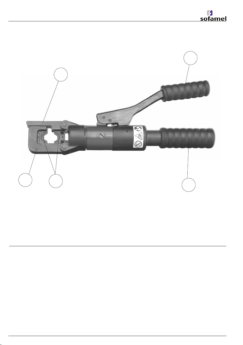
Pos.-Nr. Bezeichnung Funktion
1 Haken dient zum Öffnen des Presskopfes
2 Pumphebel dient zum Einleiten des Pressvorganges in Form von
Pumpbewegungen
3 Griff dient zum Umschalten von Druckaufbau auf
Druckablass
4 Presseinsätze Werkzeugeinsätze mit unterschiedlichen Pressprofilen
5 Haupthaken dient zur Aufnahme des oberen Presseinsatzes
4
1
2
3
5
712339 HPS50 Q7.qxp:712339 HPS50 Q7.qxp 13.11.2006 14:16 Uhr Seite 4

5
Inhaltsangabe Seite
1. Einleitung 5
2. Aufschriften 5
3. Gewährleistung 5
4. Beschreibung des hydraulischen Presswerkzeuges 5
5. Hinweise zum bestimmungsgemäßen Gebrauch 6
5.1. Bedienung des hydraulischen Presswerkzeuges 6
5.2. Verarbeitungshinweise 6
5.3. Wartungshinweise 7
5.4. Aufbewahrung und Transport des hydraulischen Presswerkzeuges 7
6. Verhalten bei Störungen am hydraulischen Presswerkzeug 7
7. Außerbetriebnahme / Entsorgung 7
8. Technische Daten 8
9. Legende 8
10. Ersatzteile 8
HPS50
1. Einleitung
Vor Inbetriebnahme des hydraulischen
Presswerkzeuges lesen Sie sich die
Bedienungsanleitung sorgfältig durch.
Benutzen Sie dieses Gerät ausschließlich für
den bestimmungsgemäßen Gebrauch.
Außerdem dürfen nur Personen, die mit dem
Gerät, den einschlägigen Vorschriften und
dem Arbeitsprozess vertraut sind, den
Pressvorgang durchführen. Diese
Bedienungsanleitung ist während der
gesamten Lebensdauer des hydraulischen
Presswerkzeuges mitzuführen.
Der Betreiber muss
– dem Bediener die Betriebsanleitung
zugänglich machen und
– sich vergewissern, dass der Bediener sie
gelesen und verstanden hat.
2. Aufschriften
Auf dem hydraulischen Presswerkzeug fin-
den Sie einen Aufkleber mit der Typbezeich-
nung, der Herstellerangabe, der Seriennum-
mer und den technischen Daten, sowie den
Gefahrenhinweisen. Abgelöste oder schlecht
erkennbare Aufkleber sind zu ersetzen.
3. Gewährleistung
Dieses hydraulische Presswerkzeug ist auf
einwandfreie Funktion überprüft.
Die Gewährleistung bei sachgemäßer
Bedienung beträgt 12 Monate ab
Lieferdatum.
Sehen die gesetzlichen Regelungen im ent-
sprechenden Land andere Fristen vor, so gel-
ten diese entsprechend.
4. Beschreibung des hydraulischen
Presswerkzeuges
Der Presskopf dieser Geräte ist im drucklosen
Zustand um 180° drehbar, um das Arbeiten
in verschiedenen Situationen zu erleichtern.
Der Schnellvorschub des Kolbens ermöglicht
mit wenigen Arbeitshüben die Fixierung des
Verbinders, der zwischen den zwei Einsätzen
liegt.
Es ist darauf zu achten, dass das Material
innerhalb der Presseinsätze liegt. Ist das nicht
der Fall, den Rücklauf einleiten und das
Material in die richtige Position bringen.
Achtung: Den Presskopf während
des Betriebes nicht mit Gewalt dre-
hen!
712339 HPS50 Q7.qxp:712339 HPS50 Q7.qxp 13.11.2006 14:16 Uhr Seite 5
6
Material verpresst ist und die automatische
Druckbegrenzung ausgelöst wird.
• Nach vollendeter Verpressung den Griff (3)
in die “Rücklauf“ <=I=> Position bringen
und es erfolgt der Rücklauf des Kolbens.
• Im Falle eines Fehlers kann der Kolben
jederzeit zurückgefahren werden.
Achtung: Vor Benutzung des
Gerätes kontrollieren, ob der Pres-
skopf richtig geschlossen ist. Durch
nicht vollständig geschlossene Einsatzhalter
kann das Gerät beschädigt werden.
Achtung:Dieses Werkzeug ist ein
Presswerkzeug.
VORSICHT: QUETSCHGEFAHR!
5.2. Verarbeitungshinweise
Das hydraulische Presswerkzeug darf nur für
den vorgesehenen Einsatzzweck verwendet
werden.
Es dürfen nur Original-Ersatzteile verwendet
werden.
Trotz gleicher Kennzahl sind die Pressbreiten
bei Cu- und Al- Presskabelschuhen und
Verbindern unterschiedlich. Bitte entnehmen
Sie die richtigen Presseinsätze aus den
Presseinsatztabellen in unserem Katalog.
Achtung: Um eine effiziente
Verpressung zu gewährleisten, den
Pumpvorgang so lange fortsetzen, bis
die automatische Druckregelung (Ventil bei
Maximaldruck) ausgelöst wird.
Achtung: Es dürfen auch bei gleicher
Kennzahl nur die für das Material
vorgesehenen Presseinsätze verwen-
det werden.
Achtung: Es dürfen keine unter
Spannung stehenden Teile verpresst
werden. Vor Arbeitsbeginn ist zwin-
gend ein spannungsfreier Zustand der zu
verpressenden Verbindung sicherzustellen.
HPS50
5. Hinweise zum bestimmungsgemäßen
Gebrauch
5.1. Bedienung des hydraulischen
Presswerkzeuges
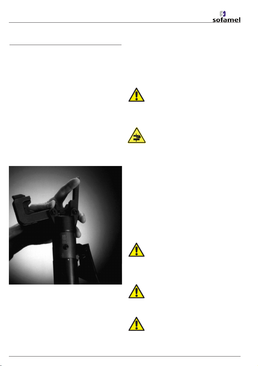
• Als erstes wird für die gewünschte
Anwendung das geeignete
Presseinsatzpaar (4) bereitgelegt. Bitte ent-
nehmen Sie die richtigen Presseinsätze aus
den Presseinsatztabellen in unserem
Katalog. Zum Einsetzen der Presseinsätze
wird als erstes der Klappkopf, mit einer
Drehbewegung nach außen, geöffnet. Nun
wird der obere Presseinsatz in die
Vertiefung des Haupthakens (5) eingescho-
ben.
Der untere Presseinsatz wird in den beweg-
lichen Einsatzhalter eingesteckt.
• Nun den Presskopf wieder schließen und-
den Griff (3) in die Position für den
Druckaufbau bringen ( =>I I<= ).
• Der Pressvorgang wird nun durch Betäti-
gen des Pumphebels (2) eingeleitet. Der
bewegliche Presseinsatz bewegt sich nun
auf das zu verpressende Material zu. Den
Pumphebel so lange betätigen, bis das
712339 HPS50 Q7.qxp:712339 HPS50 Q7.qxp 13.11.2006 14:16 Uhr Seite 6

7
5.3. Wartungshinweise
Auf die angeführten Wartungs-
empfehlugen wird hingewiesen, um eine
konstante Aufrechterhaltung des Betriebes
und eine Verlängerung der Lebensdauer des
Gerätes zu gewährleisten.
Das hydraulische Presswerkzeug ist nahezu
wartungsfrei. Alle beweglichen Teile sind
gelegentlich zu reinigen und ggf. leicht ein-
zufetten.
Achtung: Eingriffe dürfen nur von
unserem qualifizierten Personal
durchgeführt werden.
Empfehlung: Um eine optimale Lebens-
dauer des Werkzeuges zu gewährleisten
empfehlen wir eine 24-monatige außeror-
dentliche Wartung durch unser qualifiziertes
Personal.
Es dürfen keine Manipulationen am hydrau-
lischen Presswerkzeug durchgeführt werden.
5.4. Aufbewahrung und Transport des
Pressgerätes
Um das hydraulische Presswerkzeug vor
Beschädigungen zu schützen, muss es nach
Gebrauch und nachdem es gesäubert wor-
den ist, in den Transportkoffer gelegt wer-
den, der dann anschließend sicher zu ver-
schließen ist
6. Verhalten bei Störungen am
hydraulischen Presswerkzeug
a) Die Presseinsätze (4) bleiben während des
Pumpvorganges stehen:
• Prüfen ob der Presskopf richtig
verriegelt ist
• Druck nochmals ablassen und erneut
versuchen
• Das Gerät einschicken
b) Das Presswerkzeug verliert Öl
• Das Gerät einschicken
HPS50
7. Außerbetriebnahme / Entsorgung
Die Entsorgung der einzelnen Komponenten
des Aggregates muss getrennt erfolgen.
Dabei muss zuerst das Öl abgelassen werden
und an speziellen Abnahmestellen entsorgt
werden.
Achtung: Hydrauliköle stellen eine
Gefahr für das Grundwasser dar.
Unkontrolliertes Ablassen oder
unsachgemäße Entsorgung steht unter
Strafe (Umwelthaftungsgesetz).
Die restlichen Teile des Aggregates müssen
nach den jeweils gültigen Umweltstandards
entsorgt werden.
Wir empfehlen wegen möglicher Umwelt-
verschmutzung die Entsorgung durch zuge-
lassene Fachunternehmen vornehmen zu las-
sen. Eine kostenfreie Rücknahme des
Altgerätes durch den Hersteller kann nicht
zugesagt werden.
Im Bedarfsfall wenden Sie sich bitte an
unseren technischen Service:
Tel.
: +34 93 808 79 80
712339 HPS50 Q7.qxp:712339 HPS50 Q7.qxp 13.11.2006 14:16 Uhr Seite 7

8
8. Technische Daten
BETRIEB:
HYDRAULIKÖL:
PRESSKRAFT:
GEWICHT:
MAßE:
- Länge:
- Breite (geschl. Pumphebel):
-Breite (geöffn. Pumphebel):
- Höhe:
VERPACKUNG:
UMGEBUNGSTEMPERATUR:
EINSATZBEREICH:
Ölhydraulisches, handgeführtes Gerät mit zwei Vorschubs-
Geschwindigkeiten
Hydrauliköl Shell Tellus S2-V15 oder ähnliche
50KN
ca. 2,5kg (ohne Einsätze und Transportkoffer)
ca. 400 mm
160 m
315 mm
54 mm
Kunststoffkoffer
-15°C bis +50°C
• Kabelschuhe und Niederspannungsver-binder aus Kupfer bis zu
einem Querschnitt von 185 mm2
• Kabelschuhe und Mittelspannungsverbinder aus AL bis zu einem
Querschnitt von 185 mm2
• Kabelschuhe und Niederspannungsver-binder DIN ähnlich bis zu
einem Querschnitt von 185 mm2
Nicht ohne
Kopfverriegelung
betätigen
Achtung
Quetsch-
gefahr!
Vor Gebrauch
Bedienungsan-
leitung lesen
9. Legende
10. Ersatzteile
Im Rahmen des bestimmungsgemäßen Gebrauches dürfen nur die Presseinsätze (4) gewech-
selt werden.
HPS50
103451
Art. Nr. 712339 - 15.0
2
.
17
712339 HPS50 Q7.qxp:712339 HPS50 Q7.qxp 13.11.2006 14:16 Uhr Seite 8

9
Utensile oleod. da compressione – HPS50
Manuale d’istruzioni
SOFAMEL
MATERIAL ELÈCTRICO
Polìgono Industrial Plans d’Arau
C/Tomàs Edisson, 17
08787 La Pobla De Claramunt (Barcelona)
Teléfono: +34 93 808 79 80 - Fax: +34 93 808 77 00
712339 HPS50 Q7.qxp:712339 HPS50 Q7.qxp 13.11.2006 14:16 Uhr Seite 9

10
HPS50
Pos.-Nr. Descrizione Funzione
1 Gancio per l’apertura della testa dell’utensile
2 Leva di pompaggio per dare avvio alla pressatura mediante movimento
della pompa
3 Impugnatura per la commutazione tra applicazione e rilascio della
pressione
4 Matrici matrici con diversi profili di compressione
5 Gancio principale alloggiamento della matrice superiore
4
1
2
3
5
712339 HPS50 Q7.qxp:712339 HPS50 Q7.qxp 13.11.2006 14:16 Uhr Seite 10

11
1. Introduzione
Prima di mettere in servizio l’utensile oleod.
da compressione Vi preghiamo di leggere
con cura il manuale d‘uso.
Utilizzate questo utensile solo per l‘uso per
cui è stato costruito. La pressatura può essere
eseguita esclusivamente da personale che
conosca l’utensile, le disposizioni da rispetta-
re ed il procedimento da seguire. Il presente
manuale d‘uso deve essere sempre conserva-
to insieme all’ utensile oleodinamico da com-
pressione per tutta la sua vita operativa.
Il gestore dell’utensile deve:
– rendere accessibile il manuale d’uso agli
operatori
– assicurarsi che gli operatori l‘abbiano
letto e compreso.
2. Etichette
Sull’utensile idraulico di pressatura è applica-
ta un’etichetta autoadesiva che riporta il
modello, la ditta produttrice, il numero di
serie, le caratteristiche tecniche e le avverten-
ze di sicurezza.
Indice Pagina
1. Introduzione 11
2. Etichette 11
3. Garanzia 11
4. Descrizione dell’utensile oleodinamico da compressione 11
5. Indicazioni per l’uso corretto 12
5.1. Impiego dell’utensile oleodinamico da compressione 12
5.2. Indicazioni operative 12
5.3. Istruzioni per la manutenzione ordinaria 13
5.4. Conservazione e trasporto della testa per la compressione 13
6. Comportamento nel caso di guasti all‘utensile 13
7. Messa fuori servizio/smaltimento 13
8. Caratteristiche tecniche 14
9. Leggenda 14
10. Pezzi di ricambio 14
HPS50
3. Garanzia
Si garantisce la perfetta funzionalità dell’u-
tensile idraulico di pressatura.
Nel caso di uso corretto e di osservanza dei
regolari controlli prescritti, la garanzia è di
12 mesi a partire dalla data di consegna.
Se differenti, valgono i termini previsti dalle
norme di legge del paese in cui l’utensile
viene impiegato.
4. Descrizione dell’utensile
oleodinamico da compressione
In assenza di pressione, la testa dell’utensile
può essere ruotata di 180° allo scopo di faci-
litarne l’utilizzo in svariate situazioni.
L’avanzamento rapido del pistone consente il
bloccaggio del connettore fra le due matrici
con poche corse del pistone stesso.
Prima di procedere assicurarsi che l’impronta
delle matrici sia allineata alla zona da compri-
mere; in caso contrario azionare lo scarico e
ripetere il posizionamento.
Attenzione: Non ruotare la testa
forzandola quando l’utensile è in
pressione.
712339 HPS50 Q7.qxp:712339 HPS50 Q7.qxp 13.11.2006 14:16 Uhr Seite 11

12
• A pressatura ultimata, portare l’impugnatu-
ra (3) in posizione di “ritorno“, in modo da
consentire il ritorno del pistone. <=I=>
• In caso di errore, il pistone può essere fatto
arretrare in qualsiasi momento.
Attenzione: Prima di azionare l’u-
tensile assicurarsi che la testa sia ben
chiusa, una errata chiusura dei ganci
può causare danni all’utensile.
Attenzione: Questo utensile lavora
in presenza di pressione. Durante il
funzionamento non avvicinarsi all’a-
rea tra le due matrici.
PERICOLO DI SCHIACCIAMENTO!
5.2. Indicazioni operative
L’utensile idraulico di pressatura deve essere
utilizzato esclusivamente per gli scopi previ-
sti.
Utilizzare solo pezzi di ricambio originali.
Nonostante che abbiano gli stessi indici, le
larghezze di compressione dei capicorda e dei
connettori di rame e di allumio non sono
uguali. Ricavare il tipo di matrice da utilizzare
dalle relative tabelle riportate nel nostro cata-
logo.
Attenzione: Per essere sicuri di otte-
nere una buona compressione conti-
nuare a pompare fino ad ottenere
l’intervento della valvola di massima pressione
(segnalato da uno scatto)
Attenzione: Anche in caso di indici
uguali, vanno utilizzati esclusivamente
le matrici previste per il rispettivo
materiale.
Attenzione: Elementi sotto tensione
non possono essere mai tagliati.
Prima di avviare il processo lavorativo
accertarsi che il materiale da tagliare sia
privo di tensione.
HPS50
5. Istruzioni per l'uso corretto
5.1. Impiego dell’utensile oleodinamico
da compressione
• In primo luogo viene preparata la coppia di
matrici adatte (4) al processo lavorativo.
Ricavare il tipo di matrice da utilizzare dalle
relative tabelle riportate nel nostro catalo-
go. Per applicare le matrici, va innanzitutto
aperta la testa dell’utensile con un movi-
mento rotatorio verso l’esterno.
Successivamente, la matrice superiore va
infilata nella cavità del gancio principale (5).
La matrice inferiore va inserita nell’apposito
supporto mobile.
• Richiudere la testa dell’utensile e portare
l’impugnatura (3) in posizione di pressatura
( =>I I<= ).
• L’operazione di pressatura viene avviata
agendo sulla leva di pompaggio (2). La
matrice mobile si muove verso il materiale
da pressare. Agire sulla leva di pompaggio
per il tempo necessario a pressare il materi-
ale e ad attivare il limitatore automatico di
pressione.
712339 HPS50 Q7.qxp:712339 HPS50 Q7.qxp 13.11.2006 14:16 Uhr Seite 12

13
5.3. Istruzioni per la manutenzione
ordinaria
La manutenzione ordinaria è richiesta per
mantenere inalterate le prestazioni dell’u-
tensile nonché per aumentarne la durata.
L’utensile idraulico di pressatura richiede
pochissime operazioni di manutenzione.
Tutte le parti mobili devono essere pulite
ogni tanto ed eventualmente leggermente
lubrificate.
Attenzione: Manutenzioni posso-
no essere effettuate esclusivamente
dal nostro personale qualificato
Raccomandazione: Per assicurare all’appa-
reccho una vita utile ottimale, raccomandia-
mo di far eseguire ogni 24 mesi una manu-
tenzione straordinaria dal nostro personale
specializzato
La testa oleod. per la compressione non
deve subire manipolazione di nessun tipo.
5.4. Conservazione e trasporto
Per conservare l’utensile oleodinamico da
compressione si consiglia di effetturare
un’accurata pulizia dopo l’uso e di riporlo e
trasportarlo nella propria valigetta, chiusa
corretamente.
6. Comportamento in caso di guasti
all‘ utensile oleod. da compressione
a) Le matrici (4) si fermano durante il proces-
so di compressione
• Controllare che la testa dell’utensile
sia correttamente fissata.
• Rilasciare la pressione accumulata
ed effettuare un altro tentativo.
• inviare l’utensile
b) L’ utensile perde olio
• Inviare l’utensile
HPS50
7. Messa fuori servizio / smaltimento
Singoli componenti dell’utensile devono
essere smaltiti separatamente.
Come prima cosa scaricare l’olio, che deve
essere conferito in speciali puniti di raccolta.
Attenzione: Gli olii idraulici rappres-
sentano un pericolo per le acque sot-
terranee (falde acquifere).
Uno scarico non controllato o uno smaliti-
mento non adeguato è passibile di pena
(legge sulla responsabilità ambientale)
Le restanti parti dell’apparecchio devono
essere smaltite scondo i vigenti standard
ambientali
Suggeriamo, per evitare un possibile inquina-
mento ambientale, di affidare lo smalitimen-
to a ditte autorizzate. Non è assicurato il riti-
ro gratuito del vecchio apparecchio da parte
del produttore.
I
n caso di necessità o eventuali delucida-
zioni potete rivolgervi al nostro Servizio
Tecnico:
Tel.
+34 93 808 79 80
712339 HPS50 Q7.qxp:712339 HPS50 Q7.qxp 13.11.2006 14:16 Uhr Seite 13

14
Art. No. 712339 - 15.0
2
.
17
9. Leggenda
Non usare con
testa sbloccata
Attenzione!
Pericolo di
schiacciamento
Prima dell’uso
leggere le istru-
zioni d’uso
10. Pezzi di ricambio
Nell’ambito di un utilizzo dell’utensile in conformità alle disposizioni fornite, possono essere
sostituite solo le matrici (4).
103451
8. Caratteristiche tecniche
HPS50
FUNZIONAMENTO:
TIPO DI OLIO:
FORZA SVILUPPATA:
PESO:
DIMENSIONI:
- Larghezza:
-Largh. (manico pomp. chiuso):
- Largh. (manico pomp. aperto):
- Altezza:
IMBALLAGGIO:
TEMPERATURA AMBIENTE:
CAMPO DI UTILIZZO:
Oleodinamico ad azionamento manuale con sistema a due velocità
(rapido, a vuoto, lento sotto sforzo).
Olio idraulico Tellus S2-V15 Shell o equivalente.
50KN
2,5 kg ca. (matrici e custodia escluse)
400 mm ca.
160 mm
315 mm
54 mm
Custodia plastica
-15°C fino a +50°C
• Capicorda e connettori BT in rame fino alla sezione 240 mm2
• Capicorda e connettori MT in rame fino alla sezione 95 mm2
• Capicorda e connettori BT in alluminio fino alla sezione 150 mm2
• Connettori di derivazione a “C” fino alla sezione 70 mm2
• Capicorda e connettori per cavo cordato 70 mm2
712339 HPS50 Q7.qxp:712339 HPS50 Q7.qxp 13.11.2006 14:16 Uhr Seite 14

15
Hydraulic Crimping Tool – HPS50
Instructions Manual
SOFAMEL
MATERIAL ELÈCTRICO
Polìgono Industrial Plans d’Arau
C/Tomàs Edisson, 17
08787 La Pobla De Claramunt (Barcelona)
Teléfono: +34 93 808 79 80 - Fax: +34 93 808 77 00
712339 HPS50 Q7.qxp:712339 HPS50 Q7.qxp 13.11.2006 14:16 Uhr Seite 15

16
HPS50
Item Description Use
1 Jaw to open the tool head
2 Pump lever to start crimping by operating the pump
3 Handle to change from crimping to pressure release
Druckablass
4 Crimping dies crimping dies with various profiles
5 Main jaw seat for the upper die
4
1
2
3
5
712339 HPS50 Q7.qxp:712339 HPS50 Q7.qxp 13.11.2006 14:16 Uhr Seite 16

17
HPS50
Contents Page
1. Introduction 17
2. Labels 17
3. Warranty 17
4. Description of the hydraulic crimping tool 17
5. Instructions for proper use 18
5.1. Operation of the hydraulic crimping tool 18
5.2. Mounting instructions 18
5.3. Service and maintenance instructions 19
5.4. Storage and transport of the hydraulic crimping tool 19
6. Troubleshooting 19
7. Putting out of service/disposal 19
8. Specifications 20
9. Legend 20
10. Replacement parts 20
1. Introduction
Before putting into operation the hydraulic
crimping tool please read the instruction
manual carefully.
Use this tool exclusively in the field of appli-
cation it is designed for.
This tool may only be operated by a specially
trained person. The instruction manual have
to be carried along during the entire life
span of the tool.
The operator has to
• ensure that the operating instructions are
available for the user
• make sure that the user has read and
understood the operating instructions.
2. Labels
On the hydraulic crimping tool you find a
label with the type designation, the name of
the manufacturer, the serial number and the
specifications.
3. Warranty
We guarantee perfect operation of the
hydraulic crimping tool.
Subject to proper usw we grant a warranty
period of 12 months from the date of deli-
very.
The law prescriptions in the country of tool
use apply, of different.
4. Description of the hydr. crimping tool
When there is no pressure, the tool head can
be rotated 180° to facilitate operation in
various situations. Fast piston movement
allows connector locking between the two
parts of the die with just a few pump
actions.
Before proceeding, make sure that the dies
groove is aligned with the area to be crim-
ped; if not, operate the pressure release and
position again.
Warning: Do not force the head to
rotate when the tool is under pres-
sure.
712339 HPS50 Q7.qxp:712339 HPS50 Q7.qxp 13.11.2006 14:16 Uhr Seite 17

18
5. Instructions for proper use
5.1. Operation of the hydraulic crimping
tool
• First position the pair of dies (4) suited for
the job to be done. Check in the die Table
in our catalogue which dies are suitable. To
fit the dies, first open the tool head with a
rotary action outwards. Then the upper die
can be placed in the cavity to be found in
the main jaw (5).
Insert the lower die in the specific mobile
support.
• Close the tool head and move the handle
(3) to the pressing position ( =>I I<= ).
• A crimping process is initiated by activating
the pump lever (2). The connecting materi-
al is positioned in the stationary half of the
crimping dies and the moving part is
approaching the compression point. Make
pumping movements with the pump lever
until the material is cut or the pressure
interruption is triggered.
• On completion of crimping, move the
handle (3) to the return position <=I=> so
that the piston retracts.
• In the case of an error, the piston can be
retracted at any time.
Warning: Before operating the
tool, make sure that the head is
properly closed; an incorrect head
closing may damage the tool.
Warning: This tool works under
pressure. Do not go near the area
between the two dies while the tool
is working.
DANGER OF GETTING CRUSHED!
5.2. Mounting instructions
The hydraulic crimping tool must be used
only for the foreseen applications.
Use only original spare parts.
Despite the same code numbers the com-
pression width for copper and aluminium
calbe lugs and connectors is not the same.
Determine what type of die to use by consul-
ting the relevant tables in our catalogue.
Warning: For assuring a good com-
pression, carry on pumping until
intervention of the maximum pres-
sure valve (detected by a click and a metallic
sound).
Warning: Even if the code number
is idenfical, use only those dies
which are suitable for the material.
Warning: Do not crimp any live
parts. Before starting to cut please
make sure that all parts involved in
the crimping porcess are not connected to
live circuits.
HPS50
712339 HPS50 Q7.qxp:712339 HPS50 Q7.qxp 13.11.2006 14:16 Uhr Seite 18

19
HPS50
7. Putting out of service / disposal
The various components of the tool have to
be disposed of separately.
First drain the oil
and take it to a special disposal point.
Warning: Hydraulic oils represent a
danger for the ground water.
Uncontrolled draining or improper
disposal are punishable (Environment
Liability Law).
For the remaining parts of the tool please
observe the valid environment regulaions.
To avoid damage to the environment we
recommend that authorized professional
companies dispose of the tool. The manu-
facturer can not take back the tool free of
change.
If you need any assistance please con-
tact our technical service or your resai-
ler:
Phone:
+34 93 808 79 80
5.3.
Service and maintenance
instructions
The routine servicing is required for preser-
ving the tool performances, and assuring its
lasting life.
The hydraulic crimping tool is maintenance-
free, only the bolt fastenings have to be
slightly oiled.
Warning: Only our qualified and
trained staff are allowed to carry out
the maintenance work on the
hydraulic crimping tool.
Please Note: To ensure the maximum wor-
king life of the tool, we suggest having it
specially serviced every 24 months by our spe-
cialist personnel.
Never tamper with the hydraulic crimping
tool.
5.4. Storage and transport of the
hydraulic crimping tool
In order to protect the compression tool from
damage, it has to be placed into the trans-
portation case (optional) after use and care-
ful cleaning. The case has to be locked safely.
6. Troubleshooting
a) The dies (4) stop during the crimping
process
• Examine whether the hydraulic
compression head is bolted correctly.
• Pressure give up again and again try.
• Return the tool to the manufacturer
b) The compression tool loses oil.
• Return the tool to the manufacturer.
Do not open the tool or remove the
seals.
712339 HPS50 Q7.qxp:712339 HPS50 Q7.qxp 13.11.2006 14:16 Uhr Seite 19

20
Art–No. 712339 - 15.0
2
.
17
10. Replacement parts
Within the range of normal use of the tool in conformity with these instructions, the dies (4)
only can be replaced.
9. Legend
8. Specifications
103451
Never use with
unlocked wor-
khead
DANGER!
of getting
crushed!
Read the opera-
ting instructions
before use
HPS50
OPERATING:
OIL TYPE:
CRIMPING FORCE:
WEIGHT:
DIMENSIONS:
- Length:
- Width with pump. handle
in closed position:
- Width with pump. handle
in open position:
- Height
PACKING:
ENVIRONMENT TEMPERATURE.
APPLICATION FIELD:
Hand hydraulic tools with two speeds.
Hydraulic oil Tellus S2-V15 Shell or equivalent.
50KN
ca. 2,5kg (nearly (crimping dies and case excluded).
ca. 400 mm
160 mm
315 mm
54 mm
plastic case
-15°C up to +50°C
• Low Voltage copper lugs and connectors for section 185mm2
• cable terminals and medium tension connectors in AL up to sec-
tion 185mm2
• Cable terminals and low voltage connectors conforming to stan-
dards similar to DIN standards up to 185mm2
712339 HPS50 Q7.qxp:712339 HPS50 Q7.qxp 13.11.2006 14:16 Uhr Seite 20
Table of contents
Languages:
Other Sofamel Crimping Tools manuals


