Sofraser MIVI 9610 User manual

Quality System certified
instruments
9612 Version
Technical Manual
MIVI 9610
Réf : 254-31/0

Technical Manual MIVI 9612
Réf. 254-31/0 2
IMPORTANT
BEFORE STARTING THE PROCESS, IT IS VERY
IMPORTANT TO PROCEED TO THE OFFSET
ADJUSTMENT IN AIR:
The procedure of the offset adjustment is detailed in the user manual
§ 5.1:
1.
CLEAN AND DRY THE SENSOR ROD.
2.
BE SURE THE PROCESS IS EMPTY. THE ROD MUST VIBRATE IN AIR.
3.
INSTALL THE SENSOR ON THE PROCESS AND FIX IT WITH ITS 4 SCREWS.
4. REACH THE OFFSET ADJUSTMENT FUNCTION STARTING FROM THE
BLOCK “SETTINGS” AND WITH THE SECURITY CODE 2.
5. FOLLOW THE INSTRUCTIONS DISPLAYED ON THE ELECTRONICS SCREEN.
6. PRESS ON “F3” AND “OK” TO ADJUST THE OFFSET. IT MEANS THAT V
BRUT
WILL BE
SHIFTED TO THE REFERENCE 900 mV.
PRESSING ON “OK” IS POSSIBLE ONLY IF V
BRUT
IS WELL SHIFTED TO 900 mV.
A MESSAGE SAYING THE OPERATION WAS SUCCESSFUL APPEARS.

Technical Manual MIVI 9612
Réf. 254-31/0 3
TABLE OF CONTENT
1. GENERAL PRESENTATION .......................................................................................................5
1.1.
T
HE SENSOR
...............................................................................................................................5
1.2.
T
HE PROCESSOR
.........................................................................................................................5
1.3.
C
HECKING THE EQUIPMENT AT THE RECEIPT
..................................................................................6
1.4.
C
HECKING THE EQUIPMENT WHEN PLACED AT THE PROCESS
..........................................................6
1.5.
P
ERIODIC CHECKING
....................................................................................................................6
1.5.1. Offset adjustment in air.......................................................................................................6
1.5.2. Modification of the previous calibration................................................................................7
1.6.
D
IRECTIVES AND
S
TANDARDS
......................................................................................................7
1.6.1. Certification ATEX...............................................................................................................7
1.6.2. Installation in hazardous area .............................................................................................7
1.6.3. European Pressure Equipment Directive.............................................................................8
1.6.4. EMC and low voltage directive............................................................................................8
2. VISCOSITY SENSOR...................................................................................................................9
2.1.
V
ARIOUS MODELS
........................................................................................................................9
2.2.
S
ENSOR INSTALLATION
................................................................................................................9
2.2.1. Elbow mounting ................................................................................................................10
2.2.2. Plane side mounting..........................................................................................................10
2.2.3. Pot mounting, for small flow rates, or pilot plant ................................................................10
2.2.4. Special mountings.............................................................................................................10
2.2.5. Replacement cap..............................................................................................................10
2.3.
P
RACTICAL ADVICES
..................................................................................................................11
2.4.
C
HECKING
................................................................................................................................11
2.5.
S
ENSOR WIRING
........................................................................................................................11
2.6.
M
ODELS AND DIMENSIONS
.........................................................................................................13
2.7.
T
IGHTNESS
...............................................................................................................................14
3. TRANSDUCER’S MECHANICAL CHARACTERISTICS............................................................15
3.1.
H
OUSING
’
S MECHANICAL CHARACTERISTICS
................................................................................15
3.2.
T
RANSDUCER
’
S ELECTRONIC BOARD WIRING
...............................................................................15
4. PROCESSOR TECHNICAL CHARACTERISTICS.....................................................................16
4.1.
M
ECHANICAL CHARACTERISTICS
.................................................................................................16
4.2.
D
ISPLAY
...................................................................................................................................16
4.3.
K
EYBOARD
................................................................................................................................16
4.4.
B
ATTERY
..................................................................................................................................16
4.5.
C
ONSUMPTION
..........................................................................................................................17
4.6.
P
OWER SUPPLY WIRING
.............................................................................................................17
4.7.
C
ONNECTION BLOCKS
................................................................................................................17
4.8.
A
NALOG
I
NPUTS
........................................................................................................................18
4.9.
A
NALOG INPUTS CONNECTION
(
DENSIMETERS
)............................................................................18
4.10.
R
ELAY OUTPUTS
......................................................................................................................19
4.11.
A
NALOG OUTPUTS
...................................................................................................................19
4.12.
O
UTPUTS WIRING SCHEME
.......................................................................................................20
4.13.
G
ENERAL INFORMATION
...........................................................................................................20
4.14.
W
ASTES HANDLING
..................................................................................................................20
5. MOUNTING THE PROCESSOR - INSTALLATION....................................................................21

Technical Manual MIVI 9612
Réf. 254-31/0 4
6. COMMUNICATION.....................................................................................................................23
6.1.
RS232
INTERFACE
....................................................................................................................23
6.2.
RS485
INTERFACE
....................................................................................................................23
7. POWER SUPPLY.......................................................................................................................25
7.1.
C
HARACTERISTICS
....................................................................................................................25
7.2.
S
AFETY CONSIDERATIONS
..........................................................................................................25
7.3.
P
OWER SUPPLY WIRING
.............................................................................................................26
8. GENERAL CABLING SCHEMATICS.........................................................................................27
9. SPECIFIC NOTES AND MANUFACTURING PARAMETERS ...................................................29
9.1.
B
LOCK
S
ETTINGS
......................................................................................................................29
9.2.
B
LOCK
P
ARAMETERS
.................................................................................................................30
9.3.
B
LOCK
C
ONFIGURATION
............................................................................................................31

Technical Manual MIVI 9612
Réf. 254-31/0 5
1. General presentation
The measuring chain is composed of two indissociable elements : the sensor and the electronic
processor.
1.1. The sensor
Each sensor is matched with its own electronics. Before switching on, be sure that serial
numbers at the sensor and the electronics identification plates are corresponding.
The operation principle of the equipment makes that the provided viscosity information is
relative : in the same fluid, at the same conditions the information is the same. But for 2 rheologically
different fluids the response can be different (despite it is perfectly repeatable).
The sensor active part is protected by an stainless tube which must not be removed.
The sensor is fixed upon its mounting flange by means of the provided 4 long screws.
See the detailed leaflet, § 2.
1.2. The processor
Its functions:
- Powers the sensor,
- Processes the sensor’s information,
- Displays and transmits the process information : viscosity, temperature,
sensor’s frequency, outputs and relays states….
The processor is composed of two modes :
“UTILISATION” Mode :
The “UTILISATION” Mode makes it possible to visualize in different forms viscosity and
temperature values.
- Visualization with bargraphs, acquisition graph
- Access to the sensor identification data
- Access to the “ADAPTATION” Mode blocks starting from the principal menu
“ADAPTATION” Mode :
The “ADAPTATION” Mode makes it possible to adapt the displayed data, parameters, settings
and configuration of the processor according to the using conditions.
- Display block : makes it possible to display outputs and relays states, rough data, to
choose viscosity and temperature units and to choose the viscosity correction to active.
- Settings block : makes it possible to set current outputs, alarms, bargraphs and graph
scales, to choose and set the modalities parameters of kinematic viscosity calculation, to
proceed to the mounting offset adjustment, to activate and define viscosity filter and to
change the Pt100 status.
- Parameters block : makes it possible to parameter viscosity corrections, to read and
modify the compensation table, to modify security codes and to set the density coefficient.
- Configuration block : makes it possible to SOFRASER to configure the processor with the
manufacturing data (thermal drift, calibration) and to define the viscosity adjustment data.

Technical Manual MIVI 9612
Réf. 254-31/0 6
1.3. Checking the equipment at the receipt
a) At first, check the supply conformity with the ordered equipment, mainly the presence of the
parts necessary for the equipment mounting. Those to be used at the process will be given to
the concerned department, for the installation preparation.
b) Place the sensor on a soft foam plate, connect it to processor (see §3.10) and switch on. The
vibration appears at the rod, the viscosity indication is close to zero (or close to the minimal
required current value of the analog output). When touching the rod, the information has to
increase.
In case of subnormal operation a) or b), check as follows :
-
Power supply, connections, cables,
-
The good condition of the vibrating rod (no bending on knock damages).
Consult your distributor.
1.4. Checking the equipment when placed at the process
Before filling the network check that the viscosity information is stable (vibrating rod in air). If
not, check the strength of the sensor fitting, then rotate the sensor of 90° (4 possible positions).
Choose the position where the information is the most stable.
Locate this position, in order to restore it when the sensor is removed – put in place.
Adjust the mounting offset, at room temperature. The rod is vibrating in air.
When possible, note the viscosity information when a cleaning or rinsing solution is flowing.
If the original calibration is convenient, one of the 2 above mentioned values can be taken as
reference for periodic control of the equipment operation each time that the same conditions will occur
(rod in air, or in the cleaning solution). Such an operation can be assimilated to a self-checking.
If the original calibration has been modified the reference values will be of course those
obtained with the new calibration.
1.5. Periodic checking
Conformity to regulations relative to Quality Insurance implicates a periodic control of the
measuring equipment used in the manufacturing operations, taking in consideration (or correcting)
their drift in time.
It is proved that this equipment drift is negligible. However, it is good to check their aspect and
their response once a year, at the same time as the other process equipment.
A fast test is many times available, when the sensor active part is in air, or immersed in a
cleaning or rinsing solution. As long as these values stay similar, we can say that the sensor
operation is right among its whole range (if no intermediate re-programming occurred).
1.5.1. Offset adjustment in air
The clean and dry rod is vibrating in air when the offset adjustment is carried out.
The amplitude, corrected in offset, Vbrut, must be shift to the reference of 900 mV.
See User Manual §5.1.
Technical Manual MIVI 9612
Réf. 254-31/0 7
1.5.2. Modification of the previous calibration
The device has been programmed in order to answer to your needs. These features
programming steps are noticed on the features specification pages at the end of this document.
At first, be sure that the modification is necessary, and not consecutive of a non
coherent comparative information (different measuring conditions, bad standards, inaccurate
or wrong laboratory measurements,…).
The calibration parameters are protected and can only be modified with the security code.
For modifications of calibration, contact your distributor.
1.6. Directives and Standards
1.6.1. Certification ATEX
MIVI sensors are in agreement with 94/9/EC directive (ATEX) for equipments installed in
explosive gas atmospheres or in presence of combustible dust :
II 2G (gas) or II 2D (dust)
Ex d IIC T1 to T6 : gas
Ex tD A21 IP67 T75°C, T90°C, T125°C, T190°C, T290°C, T300°C : dust
Be sure the sensor’s certification is in accordance with the security level required on your
process location : Area classification, equipments group, protection method, gas type, temperature
codes…
Area classification and equipments installation rules are detailed into IEC 7910 and EN 60 079
standards for gas or EN 61 241 standards for dust.
To always keep the maximum security level of the viscometer, don’t open it. Furthermore, we
advice to install the sensor with the cable gland orientated to the floor.
Check periodically information indicated on the sensor’s identification plate are still visible.
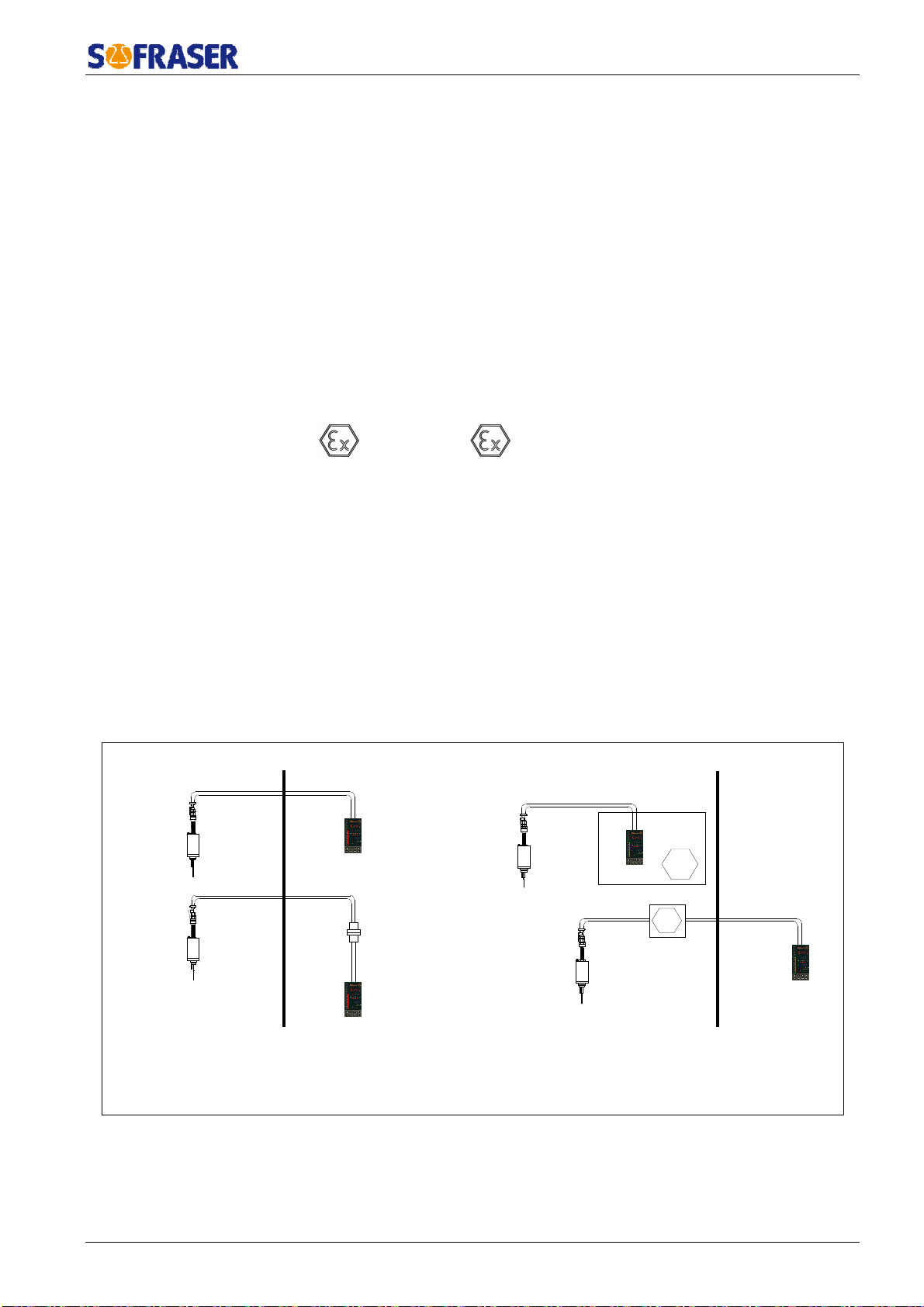
1.6.2. Installation in hazardous area
Here are the possible ways to install MIVI 9601sensors in hazardous area.
SAFE AREA
HAZARDOUS AREA SAFE AREAHAZARDOUS AREA
(1)
(2)
(3)
(1) : non-exproof connectors
(2) : exproof box (3) : exproof connection box
Ex
Ex
IMPORTANT : Always connect the sensor's body (screw on the top of the body) to the ground.

Technical Manual MIVI 9612
Réf. 254-31/0 8
1.6.3. European Pressure Equipment Directive
Up to 60 bars, MIVI sensors are in agreement with the article 3.3 of the PED 97/23/EC. In case
of higher pressure, sensors are certified one by one.
The mounting flange is an accessory to be welded on the process line. It means it can not be
individually certified but with the whole process line.
1.6.4. EMC and low voltage directive
The processor 9601 is in agreement with EMC specifications detailed into 89/336/EEC
(modified by 92/31/EEC and 93/68/EEC).
Processors 9601 are supplied by 24 VDC. So they are not subjected to the Directive Low
tension 73/23/CEEC (modified by 93/68/CEE).
MIVI sensors have been designed and manufactured according to the electrical safety rules.
Technical Manual MIVI 9612
Réf. 254-31/0 9
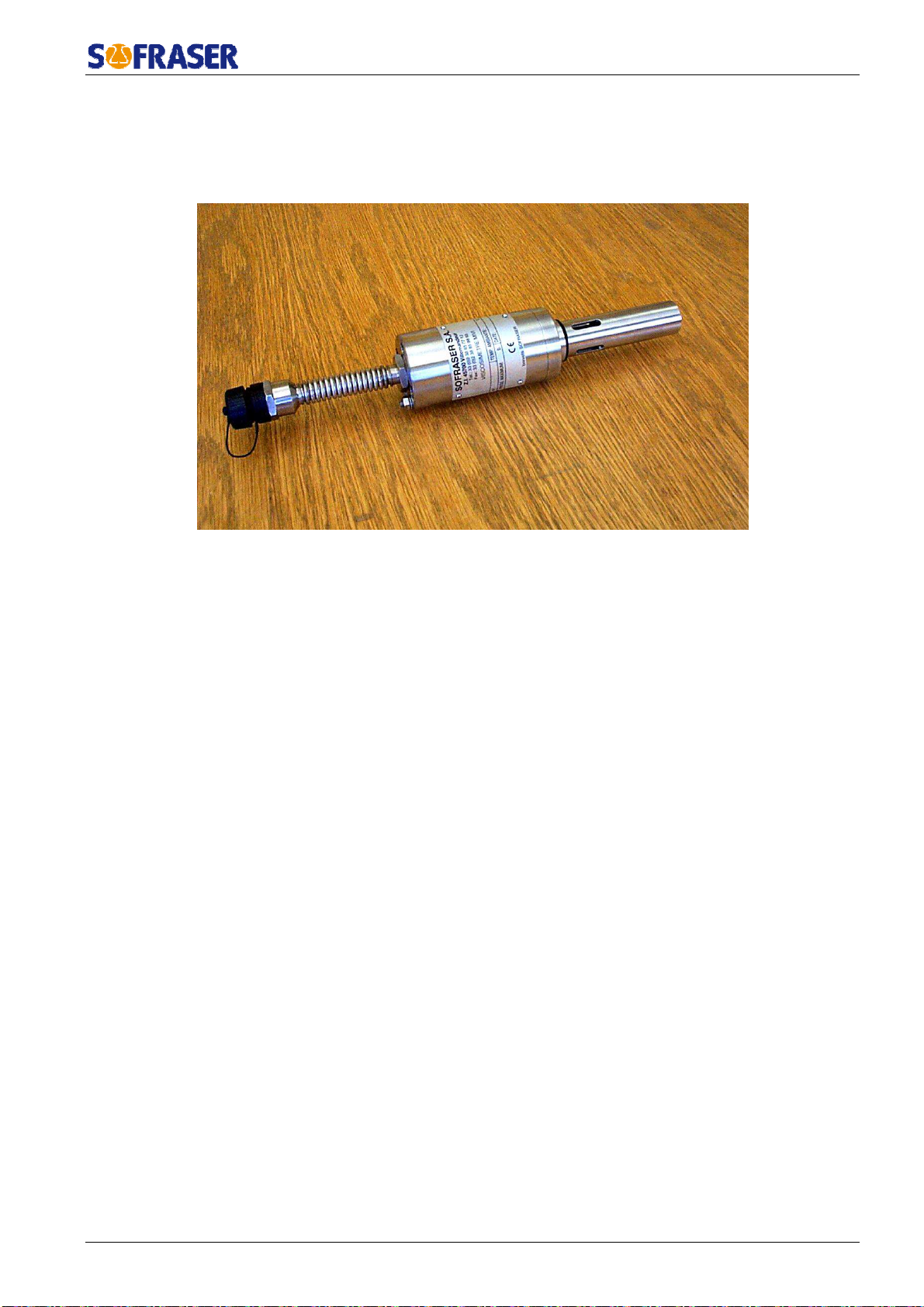
2.Viscosity sensor
2.1. Various models
•
General-purpose sensors.
•
Sanitary sensors.
•
Ex-proof sensors (ATEX, FM, JIS).
•
High pressure sensors (up to 150 bars).
•
Special models, according to the requirements (material and design).
•
When required, a temperature probe can be incorporated to the MIVI sensor.
2.2. Sensor installation
It operates at any position, even upside down. Its active part has to be permanently immersed in
the fluid (low part of the network or reactor). If the fluid temperature varies widely and fast, choose the
upside down or horizontal position, in order to allow a convenient air convection among the sensor
body.
It is screwed to its mounting flange by means of 4 screws M6X100 (or 8 screws M8 for high
pressures). The mounting flange has to be welded close to the device generating the viscosity
variations (heater, mixer, reactor, etc…). Retention, high flow velocities, strong vibrations and high
magnetic fields have to be avoided.
According to the application the mounting flange material can be :
Stainless steel Z3CND 17/11-02 (316L).
Carbon steel XC38.
Other materials, according to the requirement.

Manuel Technique MIVI 9612
Réf. 254-30/0 10
2.2.1. Elbow mounting
•
The flange is welded on a right angle tee as indicated in
pic.1.
•
The minimal pipe diameter is of 32 mm.
•
The flange and the pipe axes have to be the same.
•
The flow direction is as indicated on fig.1 (unless for
fibrous fluids where the flow is inverted and the rod
protector removed. (See §2.2.5).
•
A free area of at least 150 mm length is necessary.
Advice : choose a sensor position in order to assure a
permanent fluid renewal and to avoid the existence of
“dead zone”.
2.2.2. Plane side mounting
•
The flange is welded on a metal plate as indicated on
pic.2.
•
The free area around the vibrating rod has to be at least
∅40, 150 mm length.
•
In order to avoid parasitic vibrations, the plate where the
flange is welded must be thicker than 5 mm.
Advice : preferably choose a sensor position with the rod
to the top in order to have a total immersion of the
vibrating rod and to avoid the formation of “dead zone“.
2.2.3. Pot mounting, for small flow rates, or pilot plant
See picture 3.
2.2.4. Special mountings
The small sensor size allows numerous personalization
of its fitting according to the user's requirements. Consult
your distributor.
2.2.5. Replacement cap
Each mounting flange is provided with an obturation kit :
-
Cap and O-ring
-
4 fixing screws CHC M6 (or 8 fixing screws M8 for high
pressure sensor)
It allows the installation working when the sensor has to be
removed.
Mounting flange,
welded
150 mm mini
5 mm max.
int.
∅
32 mm mini
Pic. 1
¼
gas
Pic.3
On circulation pot
Eart terminal
Pic. 2
∅
40 mm mini
150 mm mini
17
Mounting flange
welded
Technical Manual MIVI 9612
Réf. 254-30/0 11
2.3. Practical advices
Torque at the mounting screws: 9 N.m ±1 at the M6×100 screws, or 22 N.m ±1 at the M8 screws
(for the high pressure design).
Tightness is assured by a O-ring (2 for sanitary model). Connections of ground of the sensor and
electronics must be equipotential.
Warning :
Each sensor is equipped with a guard tube in order to protect the vibrating rod. This protector must
be left on the sensor at the time of the assembly on the mounting flange. The fluid renewal is done
through the slits of the protector. He has not to be removed unless when the sensor is used in particular
conditions : on pot mounting, sanitary use, very viscous and fibrous fluids.
WARNING !
In this case, the mounting / removing of the sensor must be made with precaution, in order to
avoid to bend the vibrating rod.
A ring, with the same dimensions of the protector’s base must be placed on the head of the
sensor in order to maintain the O-ring.
IMPORTANT :
•
As soon as the sensor is removed, screw immediately its guard tube.
•
IP 67 rightness is only obtained when firmly screwing either the cable connectors, their replacing
caps, and the cable glands.
•
The minimal bending radius at the flexible pipe (electric outlet) is of 100 mm. Less radius can
generate leakage, then failure.
2.4. Checking
In case of subnormal operation, check the following points:
•
Electrical connections (connectors, cables, power supply…)
•
Remove the sensor from the process and clean it
•
Check that the vibrating rod is not bent.
When powered, check with the finger that the vibration is existing at the rod end. At this
moment, the viscosity information has to increase.
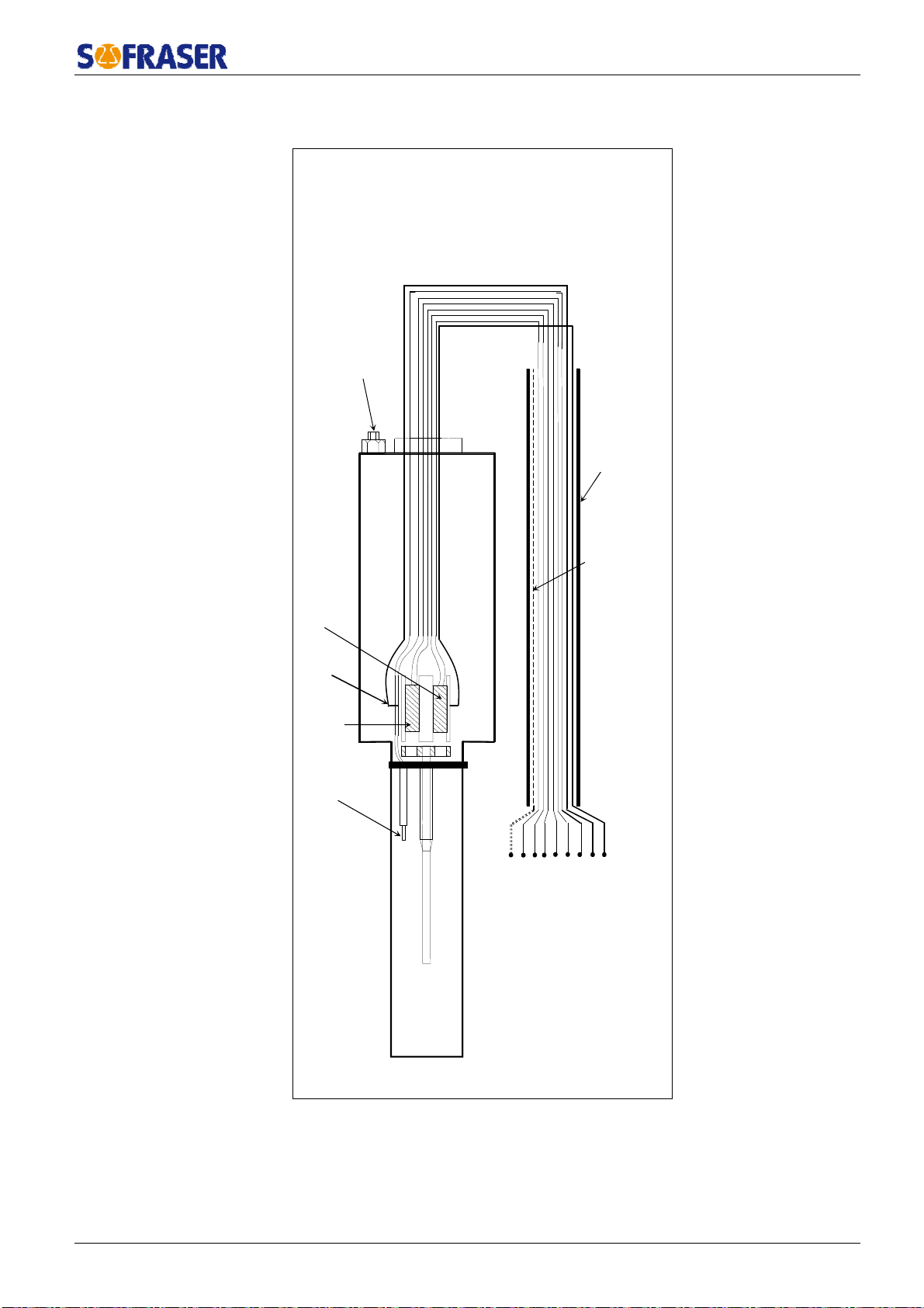
2.5. Sensor wiring
Repèrecâble
Correspondance
Couleur
A Receivingcoil Blue
B Brown
C Drivingcoil Transparent
D Black
E PT100 Red
F Yellow
J NTC Green
K White
/ Shielding
Technical Manual MIVI 9612
Réf. 254-30/0 12
Standard and explosion proof models are both equipped with cable glands. Those ones can match
the ATEX norm, depending on the MIVI version.
Eart terminal
Pic. 4
S ielding
Cable
Receiving
coil
Driving
coil
Temperature
probe
A B C D E F J K
NTC

Technical Manual MIVI 9612
Réf. 254-30/0 13
2.6. Models and dimensions
Bride de
montage
1 joint
torique
Bride de
montage
3 joints
toriques
Pic. 5
GENERAL PURPOSE
Ex
-
proof 200°C
Std 200°C
135 mm
120 mm
100 mm
17 mm
30 mm
Guard tube s ort slits Pot ¼ gas
156 mm
156 mm
HIGH PRESSURE
HP 200°C HP ex-proof 200°C
Pot ¼ gas
Guard tube long slits
Low pressure
Hig pressure
∅ 76
∅ 60
Mounting flange
∅ 99
1 o’ring
Sanitary low pressure Sanitary ig pressure
Mounting flange
∅
70
Replacement ring
Sanitary
Pic. 5

Technical Manual MIVI 9612
Réf. 254-30/0 14
2.7. Tightness
O’ ring Ø 29.82 x 2.62
Ø 76 or 79 Ø 70 or 99
O’ ring Ø 21.
95 x 1.78
O’ ring Ø 30.00 x 2.00
O’ ring Ø 30.00 x 2.50
Pic.6

Technical Manual MIVI 9612
Réf. 254-30/0 15
3. Transducer’s mechanical characteristics
3.1. Housing’s mechanical characteristics
non-ATEX version
External dimensions : (Height) 80mm * (Width) 100mm * (Length) 160mm
Tightness : IP66
Material : Aluminium
Temperature : from 0°C to 45°C
3.2. Transducer’s electronic board wiring
The transducer’s board is wired through the connector, which is plugged in the metallic box.
IMPORTANT : All boards must have the same power supply.
Connector linked to the transducer : wired by
SOFRASER
Technical Manual MIVI 9612
Réf. 254-30/0 16
4. Processor technical characteristics
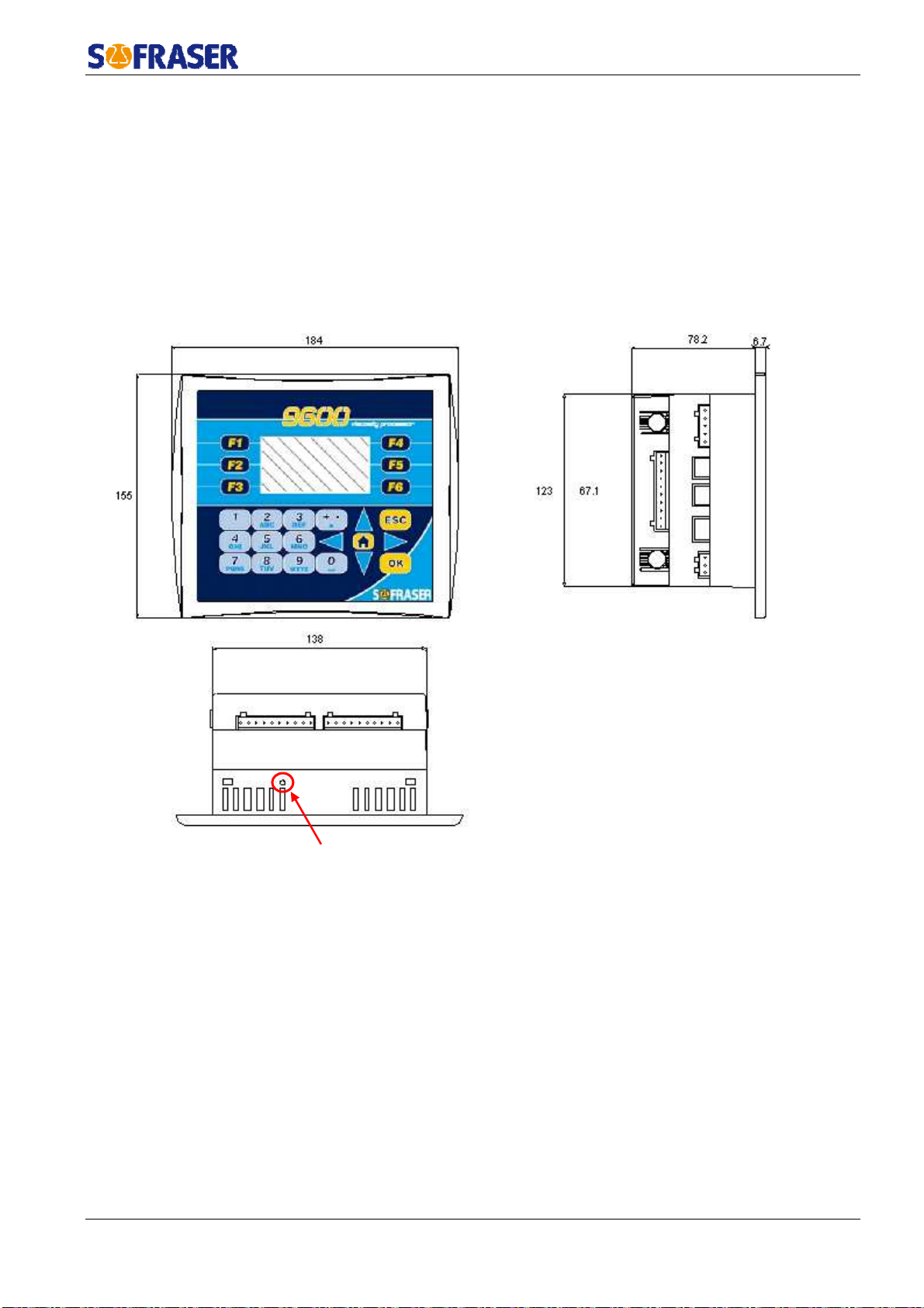
4.1. Mechanical characteristics
Dimensions behind the collar : 138 x 123 x 78.2 mm
Collar dimensions : 184 x 155 x 6.7 mm
Cut-out for assembly on panel : 141 x 126 mm. Thickness ≤5mm
Weight : about 515 g
Tightness : IP 65 with panel mounting and IP20 on rear panel
Operational temperature : 0°C to 45°C
4.2. Display
Display type : STN LCD
Illumination backlight : LED yellow
Display resolution : 128 x 64 pixels
The brightness can be adjusted using the screw on the top panel.
4.3. Keyboard
24 keys : alphanumeric keys and function keys.
4.4. Battery
The battery lifespan is about 7 years at 25°C.
Screw for brig tness
Technical Manual MIVI 9612
Réf. 254-30/0 17
4.5. Consumption
Typical power consumption : 7,2 W maximum
Current consumption : 300 mA maximum
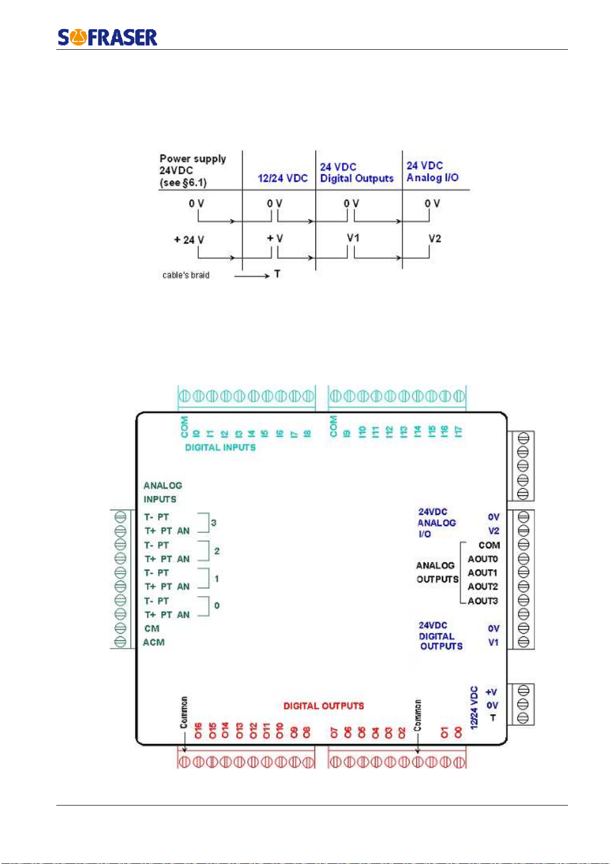
4.6. Power supply wiring
4.7. Connection blocks
On the processor back module, various categories are identified (example : Digital Inputs,
Analog Outputs).
We will call these categories "connection blocks". The diagram below identifies the various
connection blocks. The colours codes used and the name of these connection blocks are taken again
for each connection diagram.
Technical Manual MIVI 9612
Réf. 254-30/0 18
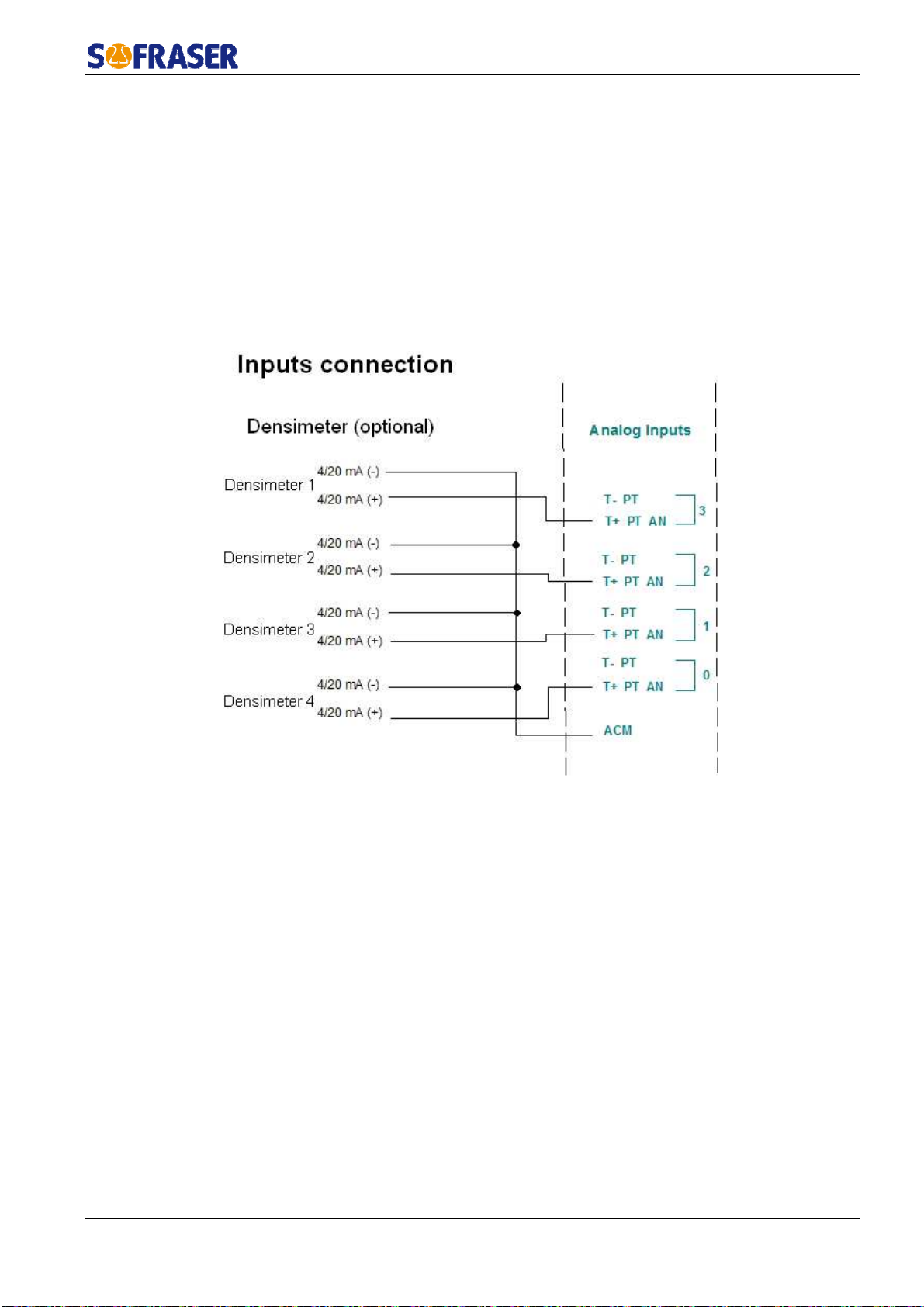
4.8. Analog Inputs
4 analog inputs are available. Resolution : 14 bits.
Analog inputs type : voltage 0-10 V, current 0-20 mA or 4-20 mA. These inputs can be used
with thermocouple or Pt100.
On 9612 electronics, these inputs are connected as 4-20mA and are specific to the plug of a
densimeter. Four densimeters can hence be connected to the 9612 module for the first four detected
sensors.
4.9. Analog inputs connection (densimeters)

Technical Manual MIVI 9612
Réf. 254-30/0 19
4.10. Relay outputs
15 relay outputs are available on this device. Based on our configuration, 13 of them are
defined, as follow :
-
12 relay outputs are attributable to the module by the user (cf User Manual § 5.2.2).
They can be used as alerts for :
-
LOW viscosity
-
HIGH viscosity
-
LOW and HIGH viscosity
-
LOW and HIGH temperature
-
1 relay output as a stand-by alert for the general working process.
How the relays operate :
-
Normal behaviour :
The relays coils are supplied and contacts are closed.
-
In case of a troubling parameter :
The relays coils stop being supplied and contacts are opened : measurements out of range,
unsupplied processor…
Tolerance for the relays :
From 02 to 07 and from 08 to 013 : 3 A max, 250VAC or 30VDC
Common : 8 A max (common plug not written, see the connecting plan)
Minimum load :
1mA à 5VDC
Lifespan :
100 000 operations with a maximum load
Response time :
10 ms
If the relays are used in order to commute some inductive loads, we clearly advise to add some
RC circuits to the load terminals or to the contacts terminals. The purpose is to decrease the impacts
of electromagnetic effects.
4.11. Analog outputs
Four analog outputs are available on the module. Their resolution is 12 bits.
They can be calibrated as 4-20mA current outputs or as 0-10V tension outputs.
The user is the one to choose how to configure the current outputs (see User Manual § 5.3.2).
The 9612 module can manage up to six sensors. So only the four first listed sensors will be able
to be connected to current outputs.
They can be used to display the viscosity and the temperature.

Technical Manual MIVI 9612
Réf. 254-30/0 20
4.12. Outputs wiring scheme
Analog outputs Digital outputs
COM Common outputs 4/20mA O16 Working process stand-by relay
AOUT0
AOUT1
Outputs assigned by t e user
AOUT2
AOUT3
4.13. General information
List of the device generic standards :
4.14. Wastes handling
Within the framework of the directive 2002/96-CE application, commonly named directive
DEEE, relating to the wastes of electric and electronic equipments, SOFRASER envisages to take in
charge the equipments arriving at the end of the lifetime.
Do not throw the equipments to the dustbin. If the user does not have the means to take in
charge the wastes of our electronic equipments, he should returned these equipments to our factory
with a signed letter confirming that it is an equipment that has to be destroyed/recycled.
Low Voltage Directive EN 61131-2 Power supply 24 VDC-not submitted
CEM Immunity EN 61000-6-2 Electro-statical discharges
Radio-frequency
Burst quick transients
CEM Emission EN 61000-6-3
EN 61000-6-4 Radio-frequency
Process variable CEI 751 Pt100
Protection CEI 529 IP 65 on front panel and IP 20 on rear
panel
Size CEI 473 Front panel : 184 * 155 mm
Cut-out : 141 * 126 mm
Climatic conditions Storage -20 to 60°C
5 to 90% HR non-condensing
Work 0 to 45°C
5 to 90% HR non-condensing
O13
O12
O11
O10
O9
O8
O7
O6
O5
O4
O3
O2
Outputs assigned by t e user
This manual suits for next models
1
Table of contents
Other Sofraser Measuring Instrument manuals


Popular Measuring Instrument manuals by other brands


Keysight Technologies
Keysight Technologies U1701B quick start guide

Water Specialties
Water Specialties Propeller meter ML03 Operation and maintenance manual

MICRO-EPSILON
MICRO-EPSILON confocalDT IFD2410 Series operating instructions

Bushnell GOLF
Bushnell GOLF PHANTOM 2 SLOPE user manual

ROOTECH
ROOTECH Accura 2300 Quick setup guide

Microtest
Microtest 6632 Series user manual


