Sofraser MIVI User manual

Technical Manual
Process tuning rod probe
for viscosity, density and temperature
measurements
Original version
REF.: 379/4
MIVI

MIVI Technical Manual
REF: 379/4 2
IMPORTANT
1° READ CAREFULLY THIS MANUAL. THE
APPLICATION OF WARRANTY IS SUBJECTED
TO STRICT OBSERVANCE OF INSTRUCTIONS.
2° THE OFFSET ADJUSTMENT IN THE AIR
MUST BE THE FIRST TASK COMPLETED
WHEN THE MIVI IS INSTALLED ON ITS
MOUTING.
Clean and dry the vibrating rod of the viscometer in order to make
it neat and dry;
Install the sensor on the process and fix it with its screws; these
must be tightened at the nominal torque;
Be sure the process is empty. The rod must be vibrating in the air;
Power on the device and wait at least 30 minutes;
Follow the instructions given in § 3.1.1 and in the electronic device
manual delivered with the equipment.
3° PRACTICAL ADVICES AND IMPORTANT
WARNINGS ARE ALSO LISTED IN § 2.4.

MIVI Technical Manual
REF: 379/4 3
Table of contents
1. GENERAL PRESENTATION ..........................................................................................................5
1.1 Principle .................................................................................................................... 5
1.2 Various models ....................................................................................................... 5
1.3 Cable wires allocation .......................................................................................... 6
1.4 Directives and Standards .................................................................................... 6
1.4.1
European Pressure Equipment Directive and EMC directive
........... 6
1.4.2
ATEX and IECEx flameproof enclosure certification
............................. 6
1.4.3
FM flameproof enclosure certification
....................................................... 7
1.4.4
ATEX and IEC Ex intrinsic safety certification
.......................................... 8
1.4.5
Installation in hazardous area
....................................................................... 9
1.4.6
Other certifications
.......................................................................................... 10
2. INSTALLATION .......................................................................................................................... 11
2.1 Checking the equipment after receipt ........................................................ 11
2.2 Sensor installation ............................................................................................... 11
2.2.1
Various mountings and models
................................................................. 12
2.2.2
Elbow mounting
.............................................................................................. 12
2.2.3
Plane side mounting
...................................................................................... 13
2.2.4
Mounting on flow cell, for small flow rates or pilot plant
.................. 13
2.2.5
Replacement cap and ring
........................................................................... 13
2.2.6
Other mountings
............................................................................................. 13
2.3 Practical advices .................................................................................................. 14
2.3.1
Flow damper
..................................................................................................... 14
2.3.2
Tightness
............................................................................................................. 14
2.3.3
Fluid homogeneity
.......................................................................................... 15
2.3.4
It is strongly recommended to carry out the measurement on a
homogenized fluid so that the measurement is representative of the fluid. . 15
2.3.5
Chemical compatibility
.................................................................................. 15
2.3.6
Temperature compatibility
.......................................................................... 15
2.3.7
Pressure compatibility
................................................................................... 15
2.3.8
Sensor handling
............................................................................................... 15
2.3.9
Mounting screws torque
............................................................................... 17
2.3.10
Grounding and wiring
.................................................................................. 17
2.4 Checking the equipment when placed in the process line ................. 17
2.5 Offset adjustment in air .................................................................................... 17
2.6 Refence point ........................................................................................................ 17
3. OPERATION AND CALIBRATION.............................................................................................. 18
3.1 MIVI utilization ...................................................................................................... 18
3.2 Periodic checking ................................................................................................ 18
3.2.1
Modification of the previous calibration
.................................................. 18

MIVI Technical Manual
REF: 379/4 4
4. MAINTENANCE .......................................................................................................................... 19
4.1 Periodic maintenance ....................................................................................... 19
4.2 Trouble shooting .................................................................................................. 21
4.3 Return instructions ............................................................................................. 21
4.4 End of life ................................................................................................................ 21
APPENDIX A: SPECIFIC CONDITIONS OF USE FOR ATEX MIVI-ADF ............................................ 22
APPENDIX B: SPECIFIC CONDITIONS OF USE FOR IECEX MIVI-ADF ........................................... 23
APPENDIX C: SPECIFIC CONDITIONS OF USE FOR ATEX AND IECEX MIVI-SI ........................... 24
ANNEX D - LIST OF OTHER SOFRASER DOCUMENTS .................................................................... 26

MIVI Technical Manual
REF: 379/4 5
1. General presentation
1.1 Principle
The measuring chain is composed of two inseparable elements: the sensor and the electronics
device that controls it (also called transducer). The sensor cannot be used with another elec-
tronic device because they are matched together as one vibrating system, and vice versa.
The provided viscosity information is relative. In the same fluid and under the same environmental
conditions, the information is the same. For two fluids with a different rheological behaviour,
the response can be different. Since it is perfectly repeatable, it just needs a different corre-
lation.
The active part of the sensor is composed of a vibrating rod held in oscillation at resonance fre-
quency (also called tuning-type) by driving magnets. When the rod is immersed into a vis-
cous material, the amplitude of the vibration is dampened. The vibration amplitude and its
frequency vary according to the viscosity and the density of the product where the rod is
immersed. The sensor receiving coil detects the response and the signal is converted to a
viscosity value through the electronics device. The factory calibration is performed with cer-
tified viscosity standards.
The transducer acquires the coils’ voltages and generates various signals. These signals represent
the properties being measured. It is also in charge of powering the whole system.
A choice of electronic from simple transducer to touchscreen PLC/HMI provides process infor-
mation (viscosity, density or temperature) through different kinds of output.
1.2 Various models
The MIVI sensor can be assembled in many different ways to match with the process needed pa-
rameters. Here are the main designs:
general standard sensor;
sanitary sensor;
Ex-proof sensors (ATEX, FM, JIS, KOSHA);
high pressure sensors (up to 1 000 bar);
special models, according to the requirements (material and design);
when required, a temperature probe can be incorporated in the MIVI sensor. Standard
temperature probe is a Pt100 class B.
Overview of the product range is available in document ref. 280 (see APPENDIX D).
Special sensors can be manufactured on demand. Contact the local distributor.

MIVI Technical Manual
REF: 379/4 6
1.3 Cable wires allocation
wire colour item
A blue Coil 1
B brown
C transparent Coil 2
D black
E red Pt100
Temperature probe
(optional)
F
G
yellow
green
N/A metal Earth
1.4 Directives and Standards
1.4.1
European Pressure Equipment Directive and EMC directive
Up to 60 bars, MIVI sensors are in accordance to the article 4.3 of the PED 2014/68/UE. In case of
higher pressure, sensors are agreed one by one.
The mounting flange is an accessory to be welded on the process line. It means it cannot be indi-
vidually certified but has to be certified with the whole process line.
MIVI sensors have been designed and manufactured according to the electrical safety rules.
1.4.2
ATEX and IECEx flameproof enclosure certification
Marking is
Be sure the sensor’s certification is in accordance to the security level required on your process
location: area classification, equipment group, protection method, gas type, temperature
codes…
MIVI sensors are in agreement with 2014/34/EU directive (ATEX) for equipment installed in explo-
sive gas atmospheres or in presence of combustible dust.
Area classification and equipment installation rules are detailed into EN 60079-0 / A11 stand-
ards and EN 60079-1 standard for gas or EN 60079-31 standard for dust.
MIVI sensors comply with the following standards for equipment installed in explosive gas atmos-
pheres or in presence of combustible dust.
IEC 60079-0: 2011 - Edition:6.0 - Explosive atmospheres - Part 0: General requirements
IEC 60079-1: 2007-04 - Edition:6 - Explosive atmospheres - Part 1: Equipment protection by flameproof enclosures "d"
IEC 60079-31: 2008 - Edition:1 - Explosive atmospheres – Part 31: Equipment dust ignition protection by enclosure 't'
To always keep the maximum security level, the proper functioning and the warranty, do not open
it.
Check as often as possible that the information indicated on the sensor’s identification plate is still
visible.
II 2G and/or II 2D and/or II 2GD
Ex db IIC T* Gb and/or Ex tb IIIC IP6X T* Db
(*) Tamb(*) see tables APPENDIX A for ATEX, APPENDIX B for IECEx
MIVI Technical Manual
REF: 379/4 7
1.4.3
FM flameproof enclosure certification
MIVI FM sensors are in agreement with FMRC-3615 class (FM) for equipment installed in explosive
gas atmospheres:
MIVI FM
For FM sensors, it is necessary to add a protection in accordance to the area’s risks level. As long as
the cable is in a hazardous area, it should be protected as recommended in the 2011 NEC
code digest, appendix IV.
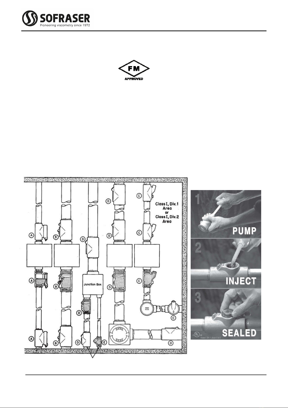
Our sensors are certified until the end of the flexible conduit, where we connected a NPT joint (see
APPENDIX D). For connecting the sensor in agreement with the class, the installer should
follow the instructions given in the 2011 NEC code digest, appendix IV.
This means a conduit seal has to be connected to our NPT joint, according to the examples you
have hereunder.
This equipment is not provided by SOFRASER.
Class I, Div. 1, Groups A, B, C & D T4A
ambient temp. range: from -20°C to 100°C

MIVI Technical Manual
REF: 379/4 8
Note: In order to protect the inner part of the sensor (body + flexible conduit) during transportation,
we use a black silicone tape to cover the NPT joint’s end. This has nothing to do with a FM approved
protection and shall be removed while being installed on site.
Hereunder are some features of the conduit seals to be installed.
EYS and EZS sealing fittings:
Restrict the passage of gases, vapors, or flames from one portion of the electrical
installation to another at atmospheric pressure and normal ambient tempera-
tures.
Limit explosions to the sealed-off enclosure.
Prevent pre-compression or “pressure piling” in conduit systems.
While not an NEC requirement, many engineers consider it good practice to sectionalize long con-
duit runs by inserting seals not more than 50 to 100 feet apart, depending on the conduit
size, to minimize the effects of “pressure piling.”
Sealing fittings are required:
at each entrance to an enclosure housing an arcing or sparking device when used
in Class I, Division 1 and 2 hazardous locations. To be located as close as practica-
ble and, in no case, more than 18" from such enclosures. The enclosure's installa-
tion instructions may specify a distance less than 18";
at each entrance of 2" size or larger to an enclosure or fitting housing terminals,
splices, or taps when used in Class I, Division 1 hazardous locations. To be located
as close as practicable and, in no case, more than 18" from such enclosures;
in conduit systems when leaving the Class I, Division 1 or Division 2 hazardous
locations;
where cables terminate at enclosures that are required to be explosion proof;
where cables leave Class I, Division 1 locations and where they leave a Class I, Di-
vision 2 location if they are attached to process equipment that may cause a pres-
sure of over 6 in. of water to be exerted on a cable end.
1.4.4
ATEX and IEC Ex intrinsic safety certification
Marking is
II 1G Ex ia IIC T6 to T1 Ga
(*) Tamb(*) see tables APPENDIX C
MIVI sensors are in agreement with ATEX directive 2014/34/EU and the associated standards
EN 60079-0 (2012) / A11 (2013), EN 60079-11 (2012), but also with the IEC 60079-0:Ed6.0 (2011)
and the IEC 60079-11:Ed6.0 (2011).
Be sure the sensor’s certification is in accordance to the security level required on your process
location: area classification, equipment group, protection method, gas type, temperature
codes…
To always keep the maximum security level, the proper functioning and the warranty, do not open
it.
Check as often as possible that the information indicated on the sensor’s identification plate is still
visible.

MIVI Technical Manual
REF: 379/4 9
1.4.5
Installation in hazardous area
Here are the possible ways to install the MIVI sensors in a hazardous area.
Ex d : zone 1 or zone 2
Always connect the sensor's Earth
screw (located on top of the body)
and all the metallic equipments (such
as Ex-proof boxes or connection
boxes) to the Earth (equipotential
ground of the hazardous site).
The transducer device is installed in the hazardous area with
the help of an Ex-proof box and linked to PLC/HMI or SCADA
in safe area
The MIVI-ADF sensor is linked to the transducer with the
help of a standard connection box
HAZARDOUS AREA
SAFE AREA
The MIVI-ADF sensor is linked to the transducer with the
help of an Ex-proof connection box
Standard installation for a MIVI-ADF linked to a transducer
Ex i : zone 0, zone 1 or zone 2
Standard installation for a MIVI-SI linked to a transducer
through intrinsic safe barriers (one for each coil plus an-
other for the PT100) (See Appendix C)
Outputs

MIVI Technical Manual
REF: 379/4 10
1.4.6
Other certifications
Japanese Ex approval is available at Sofraser distributor in Japan.
Korean Ex approval is available at Sofraser distributor in South Korea.
MIVI sensor with “standard” design, relevant flow through cell/measuring chamber/pot,
mounting flange to be welded and cap are registered under CRN n° 0F16467.2 by Absa, for the Al-
berta province (MAWP 6895kpa, design temperature 300°C, MDMT -200°C).
MIVI sensor with “sanitary” design is still manufactured according to the original file and 3A
certificate N° 1013 dated March 30th, 1999. Compared to “standard” design, the gaps and threads
were soil can accumulate and become source of contamination are eliminated, improving the effi-
ciency of the CIP (Cleaning in Place). In food and beverage, pharmaceutics, biotech, cosmetics…
MIVI with “sanitary” design is best combined with electropolish finishing that reduces the rough-
ness of the wetted parts surface, and installed on its mounting accessory without its flow damper.

MIVI Technical Manual
REF: 379/4 11
2. Installation
2.1 Checking the equipment after receipt
First and foremost, check the conformity with the ordered equipment. Mainly check if all the parts
needed to mount the equipment are delivered. The parts that are intended to be mounted
on the process shall be given to the concerned department, for the installation preparation.
Place the sensor on a soft foam plate, connect it to the processor (see Technical manual of the
processor) and switch it on. The rod shall start vibrating and the viscosity indication shall be
zero or close. When touching the rod, the value shall increase.
In case of a subnormal operation occurs, check as follows:
- power supply, connections, cables;
- vibrating rod’s shape and condition (no bending, no damages, …).
If it is not immediately used, store the viscometer in its original packaging that should also be used
for transportation.
2.2 Sensor installation
It operates in any position, even upside down. Its active part has to be permanently immersed into
the fluid (low part of the network or reactor). If the fluid temperature varies widely and fast,
choose the upside down or horizontal position, in order to allow proper air convection among
the sensor body. Nevertheless, we recommend to install the sensor in a horizontal posi-
tion or with the cable gland oriented to the ground.
The product-contact part or even the sensor body can be used up to 200, 250 or 300 °C (392, 482
or 572 °F) depending on the sensor category but the temperature at the output of cable
must not exceed the temperature written on the marking plate that is 100 °C (212 °F) by de-
fault.
It is screwed to its mounting flange with the help of 4 screws M6X100 (or 8 screws M8 or M10 for
high pressure MIVIs). The mounting flange has to be welded close to the device generating
the viscosity variations (heater, mixer, reactor, etc…). Retention, high flow velocities, strong
vibrations and high magnetic fields have to be avoided.
According to the application, the mounting flange material can be:
stainless steel 1.4404 (316L);
other materials, according to the requirement.

MIVI Technical Manual
REF: 379/4 12
2.2.1
Various mountings and models
Details about mounting accessories are available in technical leaflets reference 320, 328 and 329
(see APPENDIX D). When it normal production cycle, the vibrating rod must be continuously
and fully immersed in the fluid.
2.2.2
Elbow mounting
The flange is welded on a right angle straight tee as indi-
cated in figure 1.
The minimal pipe diameter is of 32 mm.
The length of the branch must be reduced as much as pos-
sible.
The flange and the pipe axes have to be superimposed.
The flow direction is as indicated on figure 1 (unless for fi-
brous fluids where the flow is inverted and the flow
damper removed).
A free area of at least 150 mm length is necessary.
Advice: Choose a sensor position in order to assure a
permanent fluid renewal and to avoid the
existence of “dead zones”.
5 mm max.
int.
32 mm min.
150 mm min.
Mounting flange,
welded
figure 1
high pressure
standard
replacement ring
sanitary
replacement ring
high pressure
Ex-proof MIVI
on a ¼ gas pot
Ex-proof MIVI
on a ¼ gas pot
Ø 70
mounting flange
3 O-rings
sanitary standard pressure
sanitary high pressure
mounting flange
1 O-ring
standard pressure
Ø 60
Ø 76 Ø 99
or
114
sanitary design
standard design

MIVI Technical Manual
REF: 379/4 13
2.2.3
Plane side mounting
The flange is welded on a metal plate as indicated on fig-
ure 2.
The free area around the vibrating rod has to be at least
40 and 150 mm length.
In order to avoid parasitic vibrations, the plate where the
flange is welded must be thicker than 5 mm.
Advice: Preferably choose a horizontal position for the rod
placement with all the liquid flows turned to the
top in order to avoid the apparition of bubbles.
2.2.4
Mounting on flow cell, for small flow rates or pilot plant
The small size of the sensing element allows many different mounting features according to the
user's requirements. See example on figure 3 for the mounting cell (chamber/pot).
2.2.5
Replacement cap and ring
For the standard pressure models, most of the mounting accessory sets delivered by Sofraser are
provided with an obturator kit (cap, O-ring, 4 fixing screws CHC M6) that allows the process
to work when the sensor has to be removed.
For some applications and operating conditions it may be advised to install the MIVI without its
flow damper. In this case the flow damper must be replaced by the replacement ring that is
delivered with most of the mounting flanges.
2.2.6
Other mountings
Other mountings are possible; refer to technical procedure reference 319 (see APPENDIX D).
on flow cell
figure 3
figure 2
Ø 40 mm min.
17 mm
Mounting flange,
welded
150 mm min.
MIVI Technical Manual
REF: 379/4 14
2.3 Practical advices
2.3.1
Flow damper
Each sensor is equipped with a flow damper (tube) in order to stabilize the flow around the vibrat-
ing rod. The fluid renewal is done through the slits of the damper. Slits length and width have
been set by SOFRASER according to the full scale range of the sensor and the type of mount-
ing (on pipe, on reactor, on flow cell …).
It is advised to keep it on the sensor unless the sensor is used in particular conditions: on flow cell
mounting, sanitary use, very viscous fluids. At the time of the assembly on the mounting
flange and during transport, it also protects the rod from mishandling. Before installing the
MIVI on its mounting accessory check that flow damper is firmly screwed on the neck of the
MIVI sensor.
2.3.2
Tightness
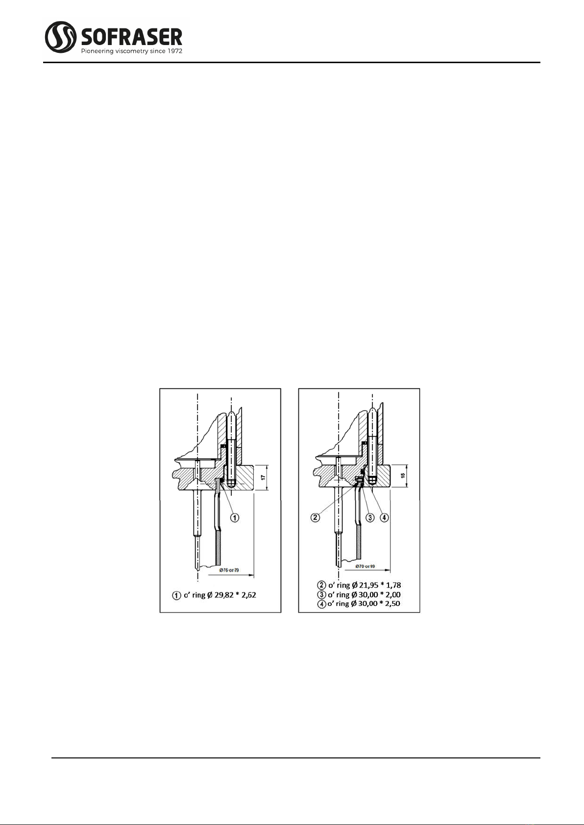
Tightness between MIVI sensor and its mounting accessory is assured by one O-ring (three for the
sanitary model). Check that the O-ring(s) material is compatible with your fluid and the op-
erating temperature.
The flow damper of MIVI with base design (left drawing) is screwed on the neck of the vibrating
rod flange. But removing the flow damper of MIVI with sanitary design requires to unscrew
the 4 M3 STHC screws (right drawing) in order to release it from the neck of the vibrating rod
flange.
When the MIVI sensor is installed without the flow damper, the replacement ring delivered with
the mounting accessory (see technical leaflets ref. 320, 328 or 329), that has the same dimen-
sions than the flow damper base, must be placed on the head of the MIVI sensor in order to
maintain the O-ring(s) and ensure tightness.
Check that the maximum operating pressure of your process is within the nominal pressure of
your MIVI sensor.
MIVI sensor with cable gland is rated IP67. Nevertheless, for long term utilization, cable gland and
cable must be oriented in the bottom direction. IP 67 tightness is only secured when the

MIVI Technical Manual
REF: 379/4 15
cable gland is firmly screwed on the cable. Cable gland should never be loosened or dis-
mantled.
After installation, proceed to the pressure proofing (limited to 150 % of the rated pressure of your
MIVI sensor).
2.3.3
Fluid homogeneity
The MIVI is fully compatible with biphasic fluids, gas emulsions and solid suspensions. There is no
impact with particles size up to 1 mm; larger particles could disturb the measurement and/or
damage the sensor.
Presence of bubbles in the fluid doesn’t disturb significantly the MIVI as long as the concentration
and diameter don’t affect the properties of the centimetric diameter size of the volume taken
into account by the measures.
2.3.4
It is strongly recommended to carry out the measurement on a homogenized fluid so
that the measurement is representative of the fluid.
2.3.5
Chemical compatibility
Check that Material Of Construction (MOC) of your MIVI sensor is compatible with your fluid and
the operating temperature.
For information, the MOC of the wetted parts of the standard MIVI sensor is 316L stainless steel. In
option, PTFE, ADLC and enamel coatings as well as special alloys and electropolish finishing
are available.
For information the sheath of the standard cable of the MIVI sensor is in PVC material and its cable
gland is in chrome-plated brass.
2.3.6
Temperature compatibility
Check that the maximum temperature of your process is within the nominal temperature of your
MIVI sensor. For information, standard MIVI sensor has a 200 °C (392°F) nominal temperature.
In option 250 or 300 °C (482 or 572 °F) are available. MIVI sensors with incorporated Pt100
temperature probe must not be used above 250 °C.
The temperature of the cable and especially at the output of cable gland must not exceed the
temperature written on the marking plate (100 °C (212 °F) by default).
2.3.7
Pressure compatibility
During normal operation, do not exceed the MIVI sensor rated pressure.
2.3.8
Sensor handling
Do not drop nor knock the MIVI sensor.
Knocking the rod will have an effect on the factory calibration. It can be corrected on site.
Bending may block the vibration of the rod and require factory maintenance.
In the case it is necessary to work without the flow damper, the mounting of the MIVI sensor must
be made with precaution, in order to avoid knocking or bending the vibrating rod.

MIVI Technical Manual
REF: 379/4 16
Same precaution must be followed when removing the MIVI sensor from its mounting accessory.
As soon as the sensor is removed, screw immediately its flow damper tube in order the se-
cure the rod.
In any case when moving or shipping don’t forget to install back the flow damper on the head of
the MIVI sensor in order to secure the rod.
Don’t knock the flexible pipe or the cable gland; the knocking the flexible pipe or the cable gland
can create damages and leaks.
The minimal bending radius at the flexible pipe (electric outlet) is of 100 mm.
A shorter radius can crush the turns, initiate cracks, generate leakage inside of the MIVI, then fail-
ure.
Don’t knock, pinch, crush, twist or bend the cable. Its minimum bending radius is 100 mm.
Don’t modify the length of the cable; modification may impact the response of the viscome-
ter. The length of the cable of ATEX Ex-proof MIVI sensor must not be reduced and must
remain at least equal to 3 meters.

MIVI Technical Manual
REF: 379/4 17
Protect the MIVI sensor against mechanical damages due to impact, pinching, crushing, twisting
and bending that aren’t covered by the warranty
2.3.9
Mounting screws torque
Torque at the mounting screws: 9 N.m 1 at the M6100 screws (4), or 21 N.m 1 at the M8 screws
(8 for the high pressure design), or 42 N.m 1 at the M10 screws (8 for the very high pressure
design).
2.3.10
Grounding and wiring
The MIVI sensor and the electronic devices must be connected to a good earth ground at same
voltage level. Use the screw dedicated to the grounding that is implemented on the MIVI
sensor.
2.4 Checking the equipment when placed in the process line
Before starting the process, check that the viscosity information is stable (vibrating rod in the air).
If not, check first the strength of the sensor fitting. Otherwise rotate the sensor of 90° (4 pos-
sible positions). Choose the position where the information is the most stable. Locate this
position in order to restore it when the sensor is removed and reinstalled.
Adjust the mounting offset, at room temperature. The rod is vibrating in the air.
2.5 Offset adjustment in air
The offset of the raw signal must be performed before utilization and introducing fluid in the pro-
cess. This is a mandatory step to ensure the reliability of the measure.
The clean and dry rod must vibrate in the air since at least half an hour before the offset adjustment
is carried out, in order to warrant the homogeneity and the stability of the MIVI temperature
on its mounting accessory (best at ambient temperature). Refer to the manual of the elec-
tronics for the detailed instructions.
The amplitude, corrected with an offset, is shifted so that the viscosity value is 0.00 cP.
When offset is confirmed, write it down as well as the raw values (see electronics manual) in the
follow up file of your instrument.
2.6 Refence point
When possible, note the viscosity information and raw values when a cleaning or rinsing solution
is flowing.
Beside of the condition “in the air”, this can be used as reference for some periodic controls of the
equipment. The operation must be done each time in the same conditions (rod in the air, or
in the cleaning solution). Such a control can be assimilated to a self-checking. If the original
calibration has been modified, the reference values will of course be those obtained with the
new calibration.

MIVI Technical Manual
REF: 379/4 18
3. Operation and calibration
3.1 MIVI utilization
Be sure that the offset in the air has been performed before introducing the fluid in the process.
Refer to the electronics manual for display, advanced data processing and output features.
3.2 Periodic checking
Conformity to regulations relative to Quality Insurance implicates a periodic control of the meas-
uring equipment used in the manufacturing operations, taking in consideration (or correct-
ing) their drift in time.
It is proved that this equipment drift is negligible. However, it is good to check their aspect and
their response once a year, at the same time as the other process equipment. A quick control
is possible from time to time, if the sensor active part is in air, or immersed in a cleaning or
rinsing solution. As long as these values stay similar, we can say that the sensor operation is
right among its whole range (if no intermediate re-programming occurred).
3.2.1
Modification of the previous calibration
The paired transducer has been programmed in order to perfectly answer to the customer’s needs.
These settings are noted in the factory “specific notes and manufacturing parameters” pages
that are delivered with the documentation. The factory calibration is performed with certified
viscosity standards (Newtonian mineral oils). In normal conditions, there is almost no drift of
the calibration. Nevertheless, the need for calibration update isn’t abnormal.
At first, be sure that the modification is necessary, and not consecutive of a non-coherent compar-
ative information (different measuring conditions, bad standards, inaccurate or wrong labor-
atory measurements …). The initial calibration parameters are protected and can only be
modified at SOFRASER. For any modification, check in the electronic manual if this operation
is allowed or contact your distributor.
Calibration update at SOFRASER workshop is the first solution. Please contact your distributor or
SOFRASER after sales team.
Calibration can be checked and updated in process conditions. Run your process in steady state
conditions, record viscometer reading, take a sample and determine its viscosity with your
reference method at the process temperature, compare and, if necessary, adjust the viscom-
eter’s response thanks to the correlation / correction feature of the electronics.
Third method is to control the response by using the on lab stand method described in SOFRASER
technical procedure (Ref.: 307-308) and Newtonian mineral type oils (see APPENDIX D).
Similar control and adjustment can be performed for the optional incorporated temperature
probe thanks to the Pt100 calibration features (see electronics manual).

MIVI Technical Manual
REF: 379/4 19
4. Maintenance
4.1 Periodic maintenance
MIVI sensor has no moving parts and can be operated without maintenance in some specific con-
ditions.
Nevertheless, SOFRASER advises to check the MIVI sensor once a year.
Each end user can reduce or increase this period of time according to his policy and specific oper-
ation conditions.
The check can be done by end user, SOFRASER distributor or SOFRASER after sales workshop.
SOFRASER advises to proceed to hereunder check:
Check Expected Action in case of not expected
status
Visual inspection of cable No damages, no cut, no twist,
…
Stop the viscometer, especially if
used in Ex area, and send the unit
back to SOFRASER for mainte-
nance of the cable
Visual inspection of the
cable gland
No damages, no broken
parts, no dismounted parts,
not loose, the cable is se-
curely held by the cable
gland, …
Stop the viscometer, especially if
used in Ex area, and send the unit
back to SOFRASER for mainte-
nance of the cable gland
Visual inspection of flexi-
ble tube
No damages, no crack, no
cut, no crushed turns, bend-
ing radius according to in-
structions
Stop the viscometer, especially if
used in Ex area, and send the unit
back to SOFRASER for mainte-
nance of the flexible tube
Visual inspection of the
junction between sensor
body and flexible tube
No backlash on the assembly
of flexible on MIVI sensor
body. Presence of the block-
ing piece on ATEX sensor
Stop the viscometer, especially if
used in Ex area, and send the unit
back to SOFRASER for mainte-
nance
Visual inspection of the
marking plate
Presence of the marking
plate, readable serial num-
ber, Ex classification, maxi-
mum operating conditions
and consistency with pro-
cess conditions and
SOFRASER electronics serial
number
Refer to delivery note and specific
notes if information aren’t readable.
Investigate why MIVI sensor is used
with electronics that hasn’t the
same serial number. Unless there is
an explained reason found the elec-
tronics that has been matched with
sensor by SOFRASER
Remove the MIVI from its mounting accessory. Take care and warrant the absence of pressure,
hazardous chemicals, excessive temperature…, before releasing the mounting screws. Check
that MIVI has been installed with its flow damper. If not and in case of doubt take much care

MIVI Technical Manual
REF: 379/4 20
to not knock nor bend the rod while removing MIVI from its mounting accessory. You can
replace the fixing screws by threaded guide rod.
Remove the flow damper. Take much care to not damage, bend or knock the rod. Do not insert
tool in the slots of flow damper in order to release the flow damper. Use appropriate solvent
to dissolve eventual traces of product.
Clean the vibrating rod.
Take much care to not damage, knock or bend the rod.
Use appropriate solvent to dissolve and remove product.
Do not use tools like hard brushes to clean the rod.
Check Expected
Action in case of not expected
status
Visual inspection of the O-
ring(s)
O-ring(s) must not be dam-
aged, altered by tempera-
ture and/or chemical reac-
tion.
Check the compatibility of the O-
ring(s) material with your product
and process conditions.
Whatever it is recommended to re-
place the O-ring(s) each time you
re-install the MIVI on your process.
Contact your distributor or
SOFRASER for spares.
Visual inspection of the vi-
brating rod
Vibrating rod must be
straight (not bent)
The larger diameter part
(6mm) of the rod must not
show any impact.
No damage or attacks on op-
tional coating
Contact your distributor or Sofraser
Contact your distributor or Sofraser
Check the compatibility of MOC
and/or coating with your fluids and
process conditions. Contact your
Distributor or Sofraser.
Check the response of the
viscometer (see chapter
3.2)
Absence of shift of response
since last check or accepta-
ble shift.
See chapter 3.2.1
Clean and dry the inside of your mounting accessory before installing the MIVI back on your pro-
cess and setting the offset in the air.
Table of contents
Other Sofraser Measuring Instrument manuals


Popular Measuring Instrument manuals by other brands


fafnir
fafnir UM Series Technical documentation

Endress+Hauser
Endress+Hauser Proline Promass 80 Brief operating instructions

Amptec Research
Amptec Research 620LK Installation, operation and maintenance manual

Lutz
Lutz ST10 Translation of the original instructions

Kingfisher
Kingfisher KI23400 Series Quick reference guide

Ecom
Ecom Ex-Tacho 10 instruction manual


