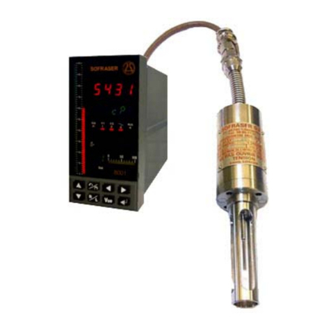
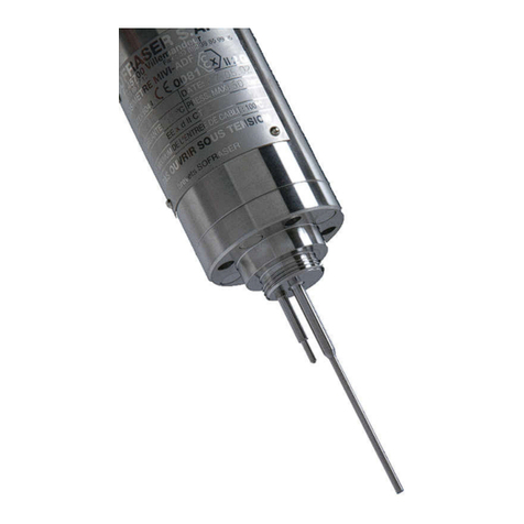
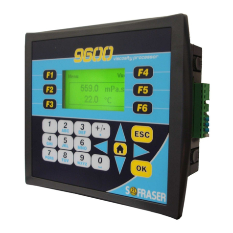
Sofraser 9601 User manual

9
601
Technical Manual
Original version
REF: 382-0
Viscosity and temperature
processor


Technical Manual 9601
REF: 382 2
IMPORTANT
THE OFFSET ADJ STMENT IN THE AIR
M ST BE THE FIRST TASK COMPLETED.
Offset adjustment procedure is detailed in § 9.1.
1. CLEAN AND DRY THE SENSOR ROD.
2. BE S RE THE PROCESS IS EMPTY. THE ROD M ST BE VIBRATING IN THE AIR.
3. INSTALL THE SENSOR ON THE PROCESS AND FIX IT WITH ITS 4 SCREWS.
4. POWER ON THE DEVICE, WAIT 15 MIN TES.
5. REACH THE OFFSET ADJ STMENT F NCTION BY ENTERING INTO MEN /
SETTINGS / OFFSET.
6. FOLLOW THE INSTR CTIONS DISPLAYED ON THE ELECTRONICS SCREEN.
7. PRESS “F3” TO ADJ ST THE OFFSET. IT MEANS THE RAW SIGNAL IN THE AIR IS
SHIFTED TO THE VOLTAGE REFERENCE DEFINED IN THE FACTORY CALIBRATION
STAGE.

Technical Manual 9601
REF: 382 3
Table of contents
1. TRANSMITTER PRINCIPLE ........................................................................................................... 5
2. PROCESSOR TECHNICAL CHARACTERISTICS ....................................................................... 6
2.1 Electronic device si e ............................................................................................................................................ 6
2.2 Mechanical characteristics ................................................................................................................................ 6
2.3 Display ............................................................................................................................................................................. 7
2.4 Keyboard ....................................................................................................................................................................... 7
2.5 Battery ............................................................................................................................................................................ 7
2.6 Consumption .............................................................................................................................................................. 7
2.7 Connection blocks .................................................................................................................................................. 7
2.8 General scheme of the electronic device................................................................................................. 8
2.9 Connections made by Sofraser ....................................................................................................................... 9
2.10 Connections to be done by the user ........................................................................................................... 9
2.11 Digital Inputs TOR ................................................................................................................................................. 10
2.12 Analog Inputs ........................................................................................................................................................... 10
2.13 Density meter (optional) ................................................................................................................................... 10
2.14 Safety considerations ............................................................................................................................................ 11
2.15 Relay outputs ............................................................................................................................................................. 11
2.16 Analog outputs ......................................................................................................................................................... 12
2.17 Outputs wiring ......................................................................................................................................................... 12
2.18 General information .............................................................................................................................................. 12
2.19 Wastes handling ..................................................................................................................................................... 13
3. PROCESSOR MO NTING-INSTALLATION ............................................................................. 14
4. COMM NICATION ........................................................................................................................ 16
4.1 Serial interface .......................................................................................................................................................... 16
4.2 Modbus communication protocol .............................................................................................................. 17
5. GENERAL INFORMATION ON THE SE OF 9601 ................................................................. 18
5.1 Navigation ................................................................................................................................................................... 18
5.2 Diagnosis ...................................................................................................................................................................... 18
5.3 Security codes ........................................................................................................................................................... 18
5.4 Modes ............................................................................................................................................................................. 18
6. TILIZATION MODE ..................................................................................................................... 19
6.1 “Bargraphs” view ..................................................................................................................................................... 19
6.2 “Compensated viscosity” view ........................................................................................................................ 19
6.3 “Acquisition graph” view .................................................................................................................................... 19
6.4 Information – version............................................................................................................................................ 19
6.5 Synoptic ...................................................................................................................................................................... 20
7. ADAPTATION MODE ..................................................................................................................... 21
8. BLOCK “DISPLAYS” ...................................................................................................................... 22
8.1 Menu of the block “Displays” .......................................................................................................................... 22
8.2 Choose the Viscosity Unit ................................................................................................................................. 22
8.3 Choose the Temperature Unit ...................................................................................................................... 22
8.4 Activate viscosity correction ........................................................................................................................... 22
8.5 Status ............................................................................................................................................................................. 23

Technical Manual 9601
REF: 382 4
8.5.1 Current outputs status .................................................................................................................................. 23
8.5.2 Alarms relay outputs status ...................................................................................................................... 23
8.5.3 Data status ........................................................................................................................................................... 23
8.6 Synoptic of Block “Display” ..............................................................................................................................24
9. BLOCK “SETTINGS” ...................................................................................................................... 25
9.1 Set the offset ............................................................................................................................................................. 25
9.2 Set the alarms .......................................................................................................................................................... 26
9.3 Set and test the current outputs ................................................................................................................. 27
9.3.1 Set the current outputs ................................................................................................................................ 27
9.3.2 Test the current outputs ............................................................................................................................. 27
9.4 Choose the method of kinematic viscosity calculation ................................................................ 28
9.5 Set the bargraphs .................................................................................................................................................. 28
9.6 Set the graph scales ............................................................................................................................................. 28
9.7 Activate the Pt100 ................................................................................................................................................. 29
9.8 Define the filter ....................................................................................................................................................... 29
9.9 Synoptic of Block “Settings” ...........................................................................................................................30
10. BLOCK “PARAMETERS” ............................................................................................................... 31
10.1 Viscosity corrections ............................................................................................................................................. 31
10.2 Compensation table ............................................................................................................................................ 32
10.2.1 Reading of the compensation table ................................................................................................... 32
10.2.2 Modification of the compensation table ........................................................................................ 32
10.3 Define the density coefficient ....................................................................................................................... 33
10.4 Modify the security codes ................................................................................................................................ 33
10.5 Synoptic of Block “Parameters”....................................................................................................................34
11. BLOCK “CONFIG RATION” ....................................................................................................... 35
11.1 Define the thermal drift table and the calibration data ............................................................... 35
11.2 Define the filter inputs ....................................................................................................................................... 35
11.3 Define the adjustment data ........................................................................................................................... 35
11.4 Synoptic of Block “Configuration” .............................................................................................................. 36
12. SPECIFIC NOTES ........................................................................................................................... 37

Technical Manual 9601
REF: 382 5
1. Transmitter principle
The measuring chain is composed of three inseparable elements: the sensor, its cable and the 9601
processor that controls it. The sensor cannot be used with another transmitter or another cable
type or length because they are all a part of the resonant loop so they are matched together as one
vibrating system.
The active part of the sensor is composed of a vibrating rod held in oscillation at resonance
frequency by driving magnets. When the rod is immersed into a viscous material, the amplitude of
the vibration is dampened. The vibration amplitude varies according to the product viscosity
where the rod is immersed.
The sensor receiving coil detects the response and the signal is converted to a viscosity value
through the electronic device. The factory calibration is performed with standard oils.
The processor acquires the coils’ amplitudes and frequency and generates various signals. These
signals represent the properties being measured. It is also in charge of powering the whole system.
It gives viscosity and temperature information through analog outputs, serial communication and
displays it. The processor also allows settings as the very important “ ero in the air” procedure.

Technical Manual 9601
REF: 382 6
2.
Processor technical characteristics
2.1
Electronic device size
The electronic box has the purpose to be fitted in a panel, close to the process line. The collar
is the only visible part, composed of a face plate and a LCD screen. It is continuously
displaying the viscosity value and, in the case there is a Pt100 probe, the temperature value.
The ID label is stick on the back panel with main information (see §2.6).
2.2
Mechanical characteristics
•Dimensions behind the collar: 138 x 123 x 106.4 mm
•Collar dimensions: 184 x 155 x 6.7 mm
•Case transducer dimensions : 66.2 x 67.1 x 28.2 mm
•Cut-out for assembly on panel: 141 x 126 mm. Thickness ≤ 5mm.
•Weight: about 515 g.
•Tightness: IP 65 with panel mounting and IP20 on rear panel.
•Operational temperature: 0 °C to 45 °C.
Screw for brightness

Technical Manual 9601
REF: 382 7
2.3
Display
•Display type: STN LCD
•Illumination backlight: LED yellow
•Display resolution: 128 x 64 pixels
The brightness can be adjusted using the screw on the top panel
.
2.4
Keyboard
24 keys: alphanumeric keys and function keys.
2.5
Battery
The battery lifespan is about 7 years at 25 °C. When the battery no longer works, the
operating parameters of the sensor are no longer stored in memory. It is then necessary to foresee
the change of the battery after 5 years of use of the sensor.
2.6
Consumption
The processor requires a 24 VDC (± 2.4 V) stabili ed and filtered power supply (not provided
by SOFRASER).
Typical power consumption: 7.2 W maximum
2.7
Connection blocks
On the processor back module, various categories are identified (example: DIGITAL INPUTS,
ANALOG OUTPUTS…).
We will call these categories "connection blocks". The diagram below identifies the various
connection blocks. The colours codes used and the name of these connection blocks are taken
again for each connection diagram.

Technical Manual 9601
REF: 382 8
2.8
General scheme of the electronic device

Technical Manual 9601
REF: 382 9
2.9
Connections made by Sofraser
All the connections in the following table are already wired when the equipment is delivered.
12/24
VDC
24 VDC
DIGITAL
O TP TS
24 VDC
ANALOG
I/O
DIGITAL
INP TS TRANSD CER
0V
0V
0V
8
+V
V1
V2
COM
9
A 1N4007-type diode (1) is cabled between the digital inputs block and the transducer in
order to protect the transducer from the unexpected power supply inversion.
2.10
Connections to be done by the user
All the wires and terminal blocks at stake here are already numbered and pre-cabled.
Equipment 12/24 VDC
Transducer
Analog
Inputs
Digital
Inputs
POWER
S PPLY
0V 0V
24V +V
Shielding bread
T (Earth)
MIVI
A 1
B C 2
D 3
G T- PT
F T+ PT
E CM
If there is no incorporated Pt100 probe, there are no E, F and G wires to connect. In the case
of a non-provided by SOFRASER external probe, be sure this is a 3-wires one.
An external circuit protection device (such as a fuse) is recommended as shown in (2).
See §3 for power supply earthing (3).
(1)
0
(3)
(2)

Technical Manual 9601
REF: 382 10
2.11
Digital Inputs TOR
18 TOR inputs are available including 2 inputs which can be used as high speed counter, shaft
encoder or for frequency measurement.
In our configuration, we only use one input (for the frequency): I0 (see §2.8).
2.12
Analog Inputs
4 analog inputs are available. Their resolution is 14 bits.
Analog inputs type: voltage 0-10 V, current 0/4-20 mA. These inputs can be used with a
thermocouple or a Pt100 probe.
On the 9601 processor, these inputs are used as follows:
Physical value
Input type
Scale
amplitude voltage 0-10V
coil voltage 0-10V
temperature (optional) Pt100 Ω – 3-wires mode -50°C to 200°C
PT100 external probe -200°C to 600°C
density (optional) current 4-20 mA
Transducer Analog
Inputs
Digital
Inputs
5
T- PT
T+ PT
4
T- PT
T+ PT
7 IO
6 ACM
Note: These connections are also made by SOFRASER.
2.13
Density meter (optional)
In the case of SOFRASER provides its density meter, this is the way to connect it to the
device.
Density meter Transducer Analog Inputs
6 ACM
0V
T
-
PT
24V
T+ PT
3
DIMF
1 (-)
2 (+)
2
1

Technical Manual 9601
REF: 382 11
2.14
Safety considerations
•Do not touch wires while the processor is ON.
•A non-isolated power supply can be used provided that the 0V is connected to the frame.
•In the event of mounting on a metal panel, standard safety considerations require that the
power supply should be earthed to avoid electrocution.
•Do not connect either the “Neutral” or “Line” signal of the 110/220VAC to the device’s 0V pin.
•In the event of voltage fluctuations or non-conformity to voltage power supply
specifications, connect the device to a filtered and stabili ed power supply.
•Double-check all wiring before turning on the power supply.
•Do not use tin on the stripped wire that might cause the strand to break.
•Install at maximum distance from high-voltage cables and power equipment.
•To avoid damaging the wire, do not exceed a maximum torque of 0.5 Nm (0.05 kgf.m).
•We recommend using crimp terminals for wiring. Use 26-14 AWG wire for all wiring
purposes.
•To maximi e the system performances, avoid electromagnetic interferences by mounting
the processor on a metal panel and earthing the power supply.
Note: The wire used to earth the power supply must not exceed 8 cm in length. If your
conditions do not permit this, do not earth the power supply (cf. step 2 § 3).
2.15
Relay outputs
15 relay outputs are available.
In our configuration, 9 relay outputs are used as follows:
Physical value Relays
Viscosity 1 NO relay for LOW threshold
1 NO relay for HIGH threshold
Compensated Viscosity
1 NO relay for LOW threshold
1 NO relay for HIGH threshold
Temperature 1 NO relay for LOW threshold
1 NO relay for HIGH threshold
Density 1 NO relay for LOW threshold
1 NO relay for HIGH threshold
Diagnosis - Dysfunction
1 NO relay
-
Normal functioning: The coils of the relay are under tension and the contact is closed.
-
In case of anomaly: The coils are not under tension and the contact is opened: measurements
out of set point, processor power supply is turned off…
-
Power cut-out:
Relays O2 to O7 and relays O8 to O15: 3 A maximum per relay, 250VAC or 30VDC
Common: 8 A maximum
Common is not located, refer to the plugging chart
Minimal charge: 1mA for 5VDC
Relays lifespan: 100 000 operations at the maximum charge
Response time: 10 ms
If these relays are used to commute some inductive charge, we advise you to add some RC
networks to the charge terminals (preferably) or to the contacts terminals. They will then lessen
the electro-magnetic phenomena.

Technical Manual 9601
REF: 382 12
2.16
Analog outputs
4 analog outputs are available. Their resolution is 12 bits.
Analog outputs type: current output 4-20 mA or voltage output 0-10 V.
In our configuration, analog outputs are used as follows:
Physical value Output type Scale
viscosity current 4-20 mA
temperature current 4-20 mA
compensated viscosity current 4-20 mA
density current 4-20 mA
2.17
Outputs wiring
Analog outputs
Digital
outputs
COM
Common outputs 4/20mA
O16
NO relay - diagnosis
AOUT0
4/20mA viscosity output
O15
NO relay HIGH - density
AOUT1
4/20mA temperature output
O14
NO relay LOW - density
AOUT2
4/20mA compensated viscosity output
O13
NO relay HIGH - comp. viscosity
AOUT3
4/20mA density output
O12
NO relay LOW - comp. viscosity
O11
NO relay HIGH - temperature
O10
NO relay LOW - temperature
O9 NO relay HIGH - viscosity
O8 NO relay LOW – viscosity
2.18
General information
List of the device generic standards:
Low Voltage Directive EN 61131-2 Power supply 24 VDC-not submitted
CEM Immunity EN 61000-6-2 Electro-static discharges
Radio-frequency
Burst quick transients
CEM Emission EN 61000-6-3
EN 61000-6-4
Radio-frequency
Process variable CEI 751 Pt100
Protection CEI 529 IP 65 on front panel and IP 20 on rear
panel
Size CEI 473 Front panel : 184 * 155 mm
Cut-out : 141 * 126 mm
Climatic conditions Storage -20 to 60°C
5 to 90% HR non-condensing
Work 0 to 45°C
5 to 90% HR non-condensing

Technical Manual 9601
REF: 382 13
2.19
Wastes handling
Within the framework of the directive 2002/96-CE application, commonly named directive
DEEE, relating to the wastes of electric and electronic equipment, SOFRASER considers taking in
charge the equipment arriving at the end of the lifetime.
Do not throw the equipment to the dustbin. If the user does not have the means to take in
charge the wastes of our electronic equipment, he should returned these equipment to our factory
with a signed letter confirming that it is an equipment that has to be destroyed/recycled.

Technical Manual 9601
REF: 382 14
3. Processor mounting-installation
Warning:
The mounting panel should not be more than 5 mm thick.
Step 1
Make a panel cut-out as following:
Step 2
Earth the power supply
-
Bore a hole of Ø4 mm that suits the NC6-32 screw
supplied.
-
Scrape the panel paint away from the contact area to
ensure a conductive connection.
-
Drive the screw into the hole and place the following
hardware in this order: washer, ring cable shoe, second
washer, spring and nut.
Note: The wire used to earth the power supply must not
exceed 8 cm in length. If your conditions do not permit this,
do not earth the power supply.
Step 3 Slide the processor into the cut-out, ensuring that the rubber seal is in place.

Technical Manual 9601
REF: 382 15
Step 4
Push the 4 mounting brackets into their slots on the processor sides as shown as
following:
Step 5
Tighten the bracket screws against the panel. Hold the mounting brackets firmly
against the processor during the screws tightening.

Technical Manual 9601
REF: 382 16
4. Communication
4.1
Serial interface
2 RS ports are available. One is a RS232 (PORT 1), the other one can be either a RS232 or a
RS485 (PORT 2). They are located on one side of the processor.
Serial ports type: RJ-11.
Caution:
-
Turn off power before making communication connections.
-
Do not connect the controller directly to a telephone or a telephone line.
-
Use shielded, twisted pair cables.
-
Minimi e the length of the connection cables. The length should not exceed 1200 m.
-
Do not cross A and B signals: the positive terminals must be wired to +, and the negative
terminals to -.
-
The RS232 port is not isolated.
-
The RS485 serial port is not isolated. If the controller is used with a non-isolated external
device, avoid potential voltage that exceeds ± 10V.To avoid damaging the system, all non-isolated
device ports should relate to the same ground signal.
-
Signals are linked to the processor’s ground, this is the same ground used by the power
supply.
RS232 characteristics
Baud rates
PORT 1 PORT 2 Voltage limits
300 to 57600 bps
300 to 115 200 bps
-20V to 20V
Pin number Function
1 DTR signal
2 0V reference
3 TxD signal - Transmission
4 RxD signal - Reception
5 0V reference
6 DSR signal
RS485 characteristics
Pin number Function
1 A signal (+)
2 *
3 *
4 *
5
*
6 B signal (-)
* pins 2 to 5 are not used for RS485 communication
.
Baud rates Nodes Voltage limits
300 to 115 200 bps Up to 32 processors -7V to 12V

Technical Manual 9601
REF: 382 17
4.2
Modbus communication protocol
Goal: read amplitude, coil, viscosity and Pt100 values using RS-485 communication
S: send from the console to the board
R: response from the board to the console
Amplitude: signal read before correction, offset and without lineari ation
Coil: signal which is an image of the sensor inner temperature
Viscosity: viscosity calculated in cP
Pt100: value in Celsius degrees of the temperature read by the probe (if there is one)
COM port characteristics
Speed: 9600 bits/s Number of bits: 8 Parity: none Stop bit: 1
Generic frame format
S = SN 3 XX XX YY YY <CRC>
R = SN 3 AA {DATA} <CRC>
SN: slave number (hexadecimal) 3: reading function
XX XX: starting point for the addresses to be read YY YY: number of words to be read
AA: read bytes number DATA: content of all the asked addresses
<CRC>: checksum (automatic)
List of a resses:
Viscosity 0x143C 4 bytes
Temperature 0x0021 2 bytes
Compensated viscosity 0x144C 4 bytes
Density 0x001F 2 bytes
Frequency 0x000D 2 bytes
Amplitude 0x001C 2 bytes
Coil 0x0007 2 bytes
Offset 0x001B 2 bytes
Example:
S = 11 03 14 3C 00 02 <CRC>
R = 11 03 04 00 08 8D F3 <CRC>
11: slave number (hexadecimal) 03: reading function
14 3C: viscosity address 00 02: number of words
04: number of bytes read 00 08 8D F3: viscosity value (0x88DF3 = 560.627 mPa.s)
<CRC>: checksum

Technical Manual 9601
REF: 382 18
5. General information on the use of 9601
Before any use, read carefully the technical manual of the MIVI sensor in order to ensure
the good installation of the unit.
5.1
Navigation
Press on this key:
to return to the previous level
to return to the “Bargraphs” view (see §6.1)
5.2
Diagnosis
When an anomaly is detected by the
processor, the symbol appears on the
main “Bargraphs” view.
Press F6 and the details about the anomaly appear.
Out of range: Viscosity.
We consider that the sensor is out of range
when viscosity exceeds 110 % of full scale
range.
Out of range:
Compensation table
The reference temperature, that can be set
on “Compensated viscosity” view (see § 6.2)
or the instantaneous temperature is out of
the table.
Alarms
Message that appears at the reach of the
low or high threshold for viscosity,
temperature or density.
Rupture
Message that appears when there is a coil
wire breakdown (viscosity or density)
generally related to a connection problem.
5.3
Security
codes
Refer to §12 (Specific notes and manufacturing parameters) and §10.4
(Modify security codes) of this Technical manual.
4 security codes, CODE 0 to CODE 3, are defined.
•Code 3 = 1111 – Modifiable
•Code 2 = 1111 – Modifiable
•
Code 1 =
Not modifiable and reserved to SOFRASER after-sales
service
•Code 0 = Not communicated and not modifiable
5.4
Modes
The utili ation mode enables to visuali e viscosity, temperature and
density values in various forms (§6).
The Adaptation mode enables to adapt parameters, settings and
configuration of the processor according to the using conditions. (§7).

Technical Manual 9601
REF: 382 19
6. tilization Mode
The Utili ation mode enables to visuali e viscosity, temperature and density values in various forms
6.1
“Bargraphs” view
“Bargraphs” view is the principal view. The following data
are displayed:
•Viscosity, temperature and density bargraphs.
•
Instantaneous viscosity, temperature according
to the selected unit and density (coefficient or
density meter).
6.2
“Compensated viscosity”
view
The viscosity at reference temperature calculation
requires knowing the viscosity evolution in function of
temperature.
Setting and saving the compensation table is done in the
“Parameters” block.
The reference temperature can be modified starting from
this view as following:
•Using the keyboard, enter the new value of the
reference temperature.
•Press OK: the modification is done and the
viscosity is re-calculated according to this new
value of reference temperature.
6.3
“Acquisition graph” view
The acquisition graph represents viscosity and
temperature.
One graph represents 120 values and the acquisition time
can be set in the “Settings” block.
For example: For an acquisition time setting at 30s, the
graph will represent an acquisition of 1 hour.
A first pressing on F6 enables to display the viscosity
graph, with the same time scale of the graph for viscosity
and temperature.
A second pressing enables to display the temperature
graph.
6.4
Information
–
version
The information view is accessible starting from the main
view by pressing on .
Instantaneous measurements
Compensated viscosity calculated at
reference temperature
Electronic version
Program version
Other manuals for 9601
1
Table of contents
Other Sofraser Measuring Instrument manuals
Popular Measuring Instrument manuals by other brands
Inficon
Inficon Sniffer line SL3000XL Translation of the original operating instructions
Kofloc
Kofloc RK1812 Series instruction manual
Endress+Hauser
Endress+Hauser Proline Promag 51 operating instructions

TENSITRON
TENSITRON BTM SERIES operating instructions

PCE Instruments
PCE Instruments PCE-2800 manual

Workzone
Workzone 11334 user guide
