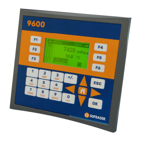
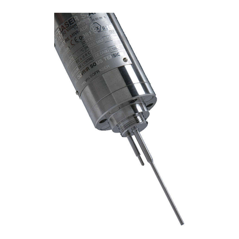
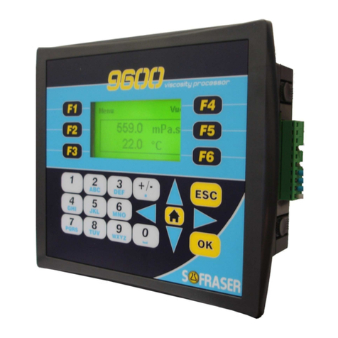
Sofraser MIVI 8001 User manual

Quality system certified
instruments
Manuel Technique
Technical Manual
MIVI 8001
Re
f
: 128-41/5

Technical Manual MIVI 8001
Ref. 128-41/5 2
IMPORTANT
BEFORE STARTING THE PROCESS, PROCEED TO
THE OFFSET IN AIR ADJUSTMENT.
IT MEANS THAT THE ROUGH SIGNAL WILL BE
SHIFTED TO THE REFERENCE "900" :
1. CLEAN AND DRY THE SENSOR ROD.
2. BE SURE THE PROCESS IS EMPTY.
3. INSTALL THE SENSOR ON THE PROCESS AND FIX IT WITH ITS 4 SCREWS.
4. ON VIEW #1, PRESS SIMULTANEOUSLY + R/L + KEYS DURING
APPROXIMATELY 3 SECONDS.
"900" MUST BE INDICATED ON THE RED DISPLAY UNTIL THE THREE KEYS ARE
PRESSED.
5. CHECK THE RED DISPLAY INDICATES "0" AS VISCOSITY VALUE.
6. PRESS CONTINEOUSLY R/L KEY AND CHECK THAT THE RED DISPLAY INDICATES
900 ±0.5.
OTHERWISE, REPEAT STEP #4.

Technical Manual MIVI 8001
Ref. 128-41/5 3
TABLE OF CONTENT
1. GENERAL PRESENTATION ...........................................................................................5
1.1. The sensor ................................................................................................................5
1.2. The processor............................................................................................................5
1.3. Checking the equipment at the receipt ...................................................................... 6
1.4. Checking the equipment when placed at the process ............................................... 6
1.5. Periodic checking ......................................................................................................6
1.5.1. Adjusting the mounting offset in air.........................................................................6
1.5.2. Modification of the previous calibration...................................................................7
1.6. Directives and standards ...........................................................................................7
1.6.1. European Directive ATEX.......................................................................................7
1.6.2. Installation in hazardous area.................................................................................7
1.6.3. European Pressure Equipment Directive................................................................ 8
1.6.4. EMC and low voltage directive................................................................................8
2. THE MIVI SENSOR .......................................................................................................... 9
2.1. Various models..........................................................................................................9
2.2. Sensor installation .....................................................................................................9
2.2.1. Elbow mounting ....................................................................................................10
2.2.2. Plane side mounting .............................................................................................10
2.2.3. On pot mounting, for small flow rates, or pilot plant .............................................. 10
2.2.4. Special mountings ................................................................................................ 10
2.2.5. Replacement cap..................................................................................................10
2.3. Practical advices...................................................................................................... 10
2.4. Checking ................................................................................................................. 11
2.5. Sensors wiring .........................................................................................................11
2.6. Models and dimensions...........................................................................................13
2.7. Tightness.................................................................................................................14
3. THE PROCESSOR......................................................................................................... 15
3.1. Mechanical characteristics ...................................................................................... 15
3.2. Power supply ...........................................................................................................15
3.3. Display.....................................................................................................................15
3.4. Universal analog inputs ........................................................................................... 16
3.5. Logic inputs .............................................................................................................16
3.6. Standard outputs (Relays 1 and 2) .......................................................................... 16
3.7. Viscosity current output (slot n°4)............................................................................16
3.8. Supervisor digital RS ...............................................................................................16
3.9. Watchdog ................................................................................................................17
3.10. Option outputs (slots N° 1 to 3)............................................................................17
3.10.1. 1 relay output board............................................................................................17
3.10.2. 2-relay output board............................................................................................17
3.10.3. 2- safety relay output board ................................................................................17
3.10.4. Current output board...........................................................................................17
3.10.5. Voltage output board .......................................................................................... 17
3.10.6. RS485/422 or RS232 board ............................................................................... 17
3.11. Connections ......................................................................................................... 18
3.12. General information ............................................................................................. 20
4. MATERIAL CONFIGURATION...................................................................................... 21
5. USER MODE..................................................................................................................22
5.1. Restoration of the configuration from the MEMOCARD ..........................................23
5.2. Adjustment of the brightness of the front panel .......................................................23
6. CONFIGURATION MODE..............................................................................................24

Technical Manual MIVI 8001
Ref. 128-41/5 4
6.1. Access to the configuration ..................................................................................... 24
6.2. Configuration type "TYPE".......................................................................................24
6.3. Inputs N° 1 to 6 "Entr.n"...........................................................................................25
6.4. Software alarm N° 1 to 4 "ALRM.n" .........................................................................25
6.5. Relays outputs 1 and 2 "REL.n" .............................................................................. 25
6.6. Outputs (slots 1 to 4) ............................................................................................... 26
6.6.1. Current or voltage board "OUT.n".........................................................................26
6.6.2. Relay board "REL.n".............................................................................................26
6.6.3. RS Link "RS.n"...................................................................................................... 26
6.6.4. Slave address "Adr"..............................................................................................27
6.7. Display.....................................................................................................................27
6.7.1. Display 1 block "AFFI.1" .......................................................................................27
6.7.2. Display 2 block "AFFI.2" .......................................................................................27
6.8. Change to User mode "UTIL" .................................................................................. 27
7. ADAPTATION MODE ....................................................................................................28
7.1. Access to the ADAPTATION mode .........................................................................28
7.2. ADAPTATION blocks diagrams...............................................................................29
7.3. Alarm Block "ALARME" ........................................................................................... 30
7.4. Filter block "FILTRE" ...............................................................................................30
7.5. Cycle information block "INFO" ...............................................................................31
7.6. Memocard block "MCARD"...................................................................................... 31
7.6.1. Save : From the device to the Memocard .............................................................31
7.6.2. Load : from the Memocard to the device .............................................................. 31
7.7. Security block "SECUR" ..........................................................................................31
7.7.1. Global locking "GLOBAL" .....................................................................................31
7.7.2. Adaptation blocks locking "REGU"…"PLG.HOR" .................................................31
7.8. Linearization block "LINEAR" .................................................................................. 32
7.9. Timer block "TIMER" ...............................................................................................32
7.10. Constants block "CONST" ...................................................................................32
7.11. Parameters block "PARAM".................................................................................33
7.12. Program block "PRGRAM"................................................................................... 33
8. DIGITAL COMMUNICATION .........................................................................................34
8.1. MODBUS slave and addressing .............................................................................. 34
8.2. Slicing of the bit memory that can be addressed.....................................................34
8.3. Slicing of the word memory (16 bits) ....................................................................... 34
9. SPECIFIC NOTES AND MANUFACTURING PARAMETERS ...................................... 37
9.1. Configuration Mode .................................................................................................37
9.2. Adaptation Mode .....................................................................................................38
10. ERROR MESSAGES .....................................................................................................41

Technical Manual MIVI 8001
Ref. 128-41/5 5
1. General presentation
1.1. The sensor
Each sensor is matched with its own electronics. Before switching on, be sure that serial numbers at
the sensor and the electronics identification plates are corresponding.
The operation principle of the equipment makes that the provided viscosity information is relative: in
the same fluid, at the same conditions the information is the same. But for 2 rheologically different
fluids the response can be different (despite it is perfectly repeatable).
The sensor active part is protected by an stainless tube which must not be removed.
The sensor is fixed upon its mounting flange by means of the provided 4 long screws.
See the detailed leaflet, § 2.
1.2. The processor
Its functions:
− Powers the sensor;
− Processes the sensor’s information;
− Displays and transmits the process information : viscosity, temperature, sensor’s frequency,
outputs states …
It is composed of three software modes:
• « USER» Mode :
Used for the working mode, it allows:
− Visualizing viscosity, temperature and outputs states (relays, digital link,…);
− Adjusting the offset in air;
− Accessing to ADAPTATION and CONFIGURATION modes;
See detailed leaflet, § 5.
• « ADAPTATION » Mode:
Allows adjusting the functioning parameters as:
− The table of linearization (Re-calibration and thermal drift compensation);
− Hysteresis and thresholds alarms values;
− Scale of bargraphs;
− Filtering parameters of inputs and outputs;
See detailed leaflet, § 7.
• « CONFIGURATION » Mode:
Allows defining:
− The inputs parameters ;
− The alarm types;
− The outputs parameters (relays, analogs, digital);
See detailed leaflet, § 6.

Technical Manual MIVI 8001
Ref. 128-41/5 6
1.3. Checking the equipment at the receipt
a- At first, check the supply conformity with the ordered equipment, mainly the presence of the parts
necessary for the equipment mounting. Those to be used at the process will be given to the
concerned department, for the installation preparation.
b- Place the sensor on a soft foam plate, connect it to the 8001 module (see § 3.11), and then switch
on. The vibration appears at the rod, and the indication (display and output) is close to the minimal
required values. When touching the rod, the information has to increase.
In case of subnormal operation, check as follows :
− The power supply, the connections, and the cables.
− The good condition of the vibrating rod (no bending on knock damages).
Consult your Distributor.
1.4. Checking the equipment when placed at the process
Before filling the network check that the viscosity information is stable (vibrating rod in air). If not,
check the strength of the sensor fitting, then rotate the sensor of 90° (4 possible positions). Choose
the position where the information is the most stable.
Locate this position, in order to restore it when the sensor is removed – put in place.
Adjust the offset in air, at room temperature. When possible, note the viscosity information when a
cleaning or rinsing solution is flowing.
If the original calibration is convenient, one of the 2 above mentioned values can be taken as
reference for periodic control of the equipment operation each time that the same conditions will occur
(rod in air, or in the cleaning solution). Such an operation can be assimilated to a self-checking.
If the original calibration has been modified the reference values will be of course those obtained with
the new calibration.
1.5. Periodic checking
Conformity to regulations relative to Quality Insurance implicates a periodic control of the measuring
equipment used in the manufacturing operations, taking in consideration (or correcting) their drift in
time.
It is proved that this equipment drift is negligible. However, it is good to check their aspect and their
response once a year, at the same time as the other process equipment.
A fast test is many times available, when the sensor active part is in air, or immersed in a cleaning or
rinsing solution. As long as these values stay similar, we can say that the sensor operation is right
among its whole range (if no intermediate re-programming occurred).
1.5.1. Adjusting the mounting offset in air
The sensor active part must be clean and dry.
Press simultaneously the following keys of the device’s front panel :
+ R/L +
Be sure before you stop pushing the keys that the red display indicates "900".
The upper display (red one) must indicate “0” when you stop pushing the keys.

Technical Manual MIVI 8001
Ref. 128-41/5 7
1.5.2. Modification of the previous calibration
The device has been programmed in order to answer to your needs. These features programming
steps are noticed on the features specification pages at the end of this document.
At first, be sure that the modification is necessary, and not consecutive of a non coherent
comparative information (different measuring conditions, bad standards, inaccurate or wrong
laboratory measurements,…).
To re-calibrate the viscometer, measure several viscosities of standard oils and then, transfer the
values in the table n°2 of the electronic processor. Refer to the User Manual 8001 to know each steps
of a re-calibration.
1.6. Directives and standards
1.6.1. European Directive ATEX
MIVI sensors are in agreement with 94/9/EC directive (ATEX) for equipments installed in explosive
gas atmospheres or in presence of combustible dust :
II 2G (gas)
II 2D (dust)
Ex d IIC T1 to T6 : gas
Ex tD A21 IP67 T75°C, T90°C, T125°C, T190°C, T290°C, T300°C : dust
Be sure the sensor’s certification is in accordance with the security level required on your process
location : Area classification, equipments group, protection method, gas type, temperature codes…
Area classification and equipments installation rules are detailed into IEC 7910 and EN 60079
standards for gas or EN 61241 standards for dust.
To always keep the maximum security level of the viscometer, don’t open it. Furthermore, we advice
to install the sensor with the cable gland orientated to the floor.
Check periodically information indicated on the sensor’s identification plate are still visible.
1.6.2. Installation in hazardous area
Here are the possible ways to install MIVI sensors in hazardous area.
SAFE AREA
HAZARDOUS AREA SAFE AREAHAZARDOUS AREA
(1)
(2)
(3)
(1) : non-exproof connectors
(2) : exproof box (3) : exproof connection box
Ex
Ex
IMPORTANT : Always connect the sensor's body (screw on the top of the body) to the ground.

Technical Manual MIVI 8001
Ref. 128-41/5 8
1.6.3. European Pressure Equipment Directive
Up to 60 bars, MIVI sensors are in agreement with the article 3.3 of the PED 97/23/EC. In case of
higher pressure, sensors are certified one by one.
The mounting flange is an accessory to be welded on the process line. It means it can not be
individually certified but with the whole process line.
1.6.4. EMC and low voltage directive
MIVI 8001 is in agreement with EMC specifications detailed into 89/336/EEC (modified by 92/31/EEC
and 93/68/EEC).
8001 processor is also in agreement with the low voltage directive 73/23/EEC (modified by
93/68/EEC).
MIVI sensors have been designed and manufactured according to the electrical safety rules.

Technical Manual MIVI 8001
Ref. 128-41/5 9
2. The MIVI sensor
2.1. Various models
• General purpose sensors
• Sanitary sensors (special design for no retention areas).
• Ex-proof sensors (ATEX, FM or JIS approvals).
• High-pressure sensors up to 150 bars (reinforced fitting).
• Special models, according to the requirements (in design and material).
• When required, a temperature probe can be incorporated to the MIVI sensor.
2.2. Sensor installation
It operates at any position, even upside down. Its active part has to be permanently immersed in the
fluid (low part of the network or reactor). If the fluid temperature varies widely and fast, choose the
upside down or horizontal position, in order to allow a convenient air convection among the sensor
body.
It is screwed to its mounting flange by means of 4 screws M6X100 (or 8 screws M8 for high
pressures). The mounting flange has to be welded close to the device generating the viscosity
variations (heater, mixer, reactor, etc…). Retention, high flow velocities, strong vibrations and high
magnetic fields have to be avoided.
According to the application the mounting flange material can be :
Stainless steel Z3CND 17/11-02 (316L).
Carbon steel XC38
Other materials, according to the requirement.

Technical Manual MIVI 8001
Ref. 128-41/5 10
2.2.1. Elbow mounting
2.2.2. Plane side mounting
2.2.3. On pot mounting, for small flow rates, or pilot plant
See fig.3.
2.2.4. Special mountings
2.2.5. Replacement cap
2.3. Practical advices
The flange is welded on a right angle tee as indicated in
fig.1.
• The minimal pipe diameter is of 32 mm.
• The flange and the pipe axes have to be superjacent.
• The flow direction is as indicated on fig.1 (unless for
fibrous fluids where the flow is inverted and the rod
protector removed.
A free area of at least 150 mm length is necessary.
• The flange is welded as indicated on fig.2.
• The free area around the vibrating rod has to be at
least ∅40, 150 mm length.
• In order to avoid parasitic vibrations, the plate where
the flange is welded must be thicker than 5 mm.
The small sensor size allows numerous personalization
of its fitting according to the user's requirements.
Consult
y
our Distributor.
Each mounting flange is provided with the
corresponding cap and its accessories (screws and
gaskets). It allows the installation working when the
sensor has to be removed.
Torque at the mounting screws: 9 N.m ±1 at the M6×100
screws, or 22 N.m ±1 at the M8 screws (for the high
pressure design).
Notes:
Each sensor is equipped with a guard tube in order to
protect the vibrating rod. In most cases, it is designed
according to the application, and has not to be removed,
unless when it disturbs the sensor operation: on pot
mounting, sanitary use, very viscous and fibrous fluids,
where a replacement ring is used.
Mounting flange,
welded
150 mm
5 mm
int.
∅
32 mm mini
Fig. 1
∅
40 mm mini
150 mm
17
Mounting flange,
welded
Fig. 2
¼
g
as
Fig.3
On circulation pot
Weight : 5,6 kg
Earth terminal

Technical Manual MIVI 8001
Ref. 128-41/5 11
WARNING ! In this case, the mounting / removing of the sensor must be made with precaution, in
order to avoid to bend the vibrating rod.
A ring, with the same dimensions of the protector’s base must be placed on the head of the sensor in
order to maintain the O-ring.
IMPORTANT :
• As soon as the sensor is removed, screw immediately its guard tube.
• IP 67 rightness is only obtained when firmly screwing either the cable connectors, their replacing
caps, and the cable glands.
• The minimal bending radius at the flexible pipe (electric outlet) is of 100 mm. Less radius can
generate leakage, then failure.
2.4. Checking
In case of subnormal operation, check the following points:
• Electrical connections (connectors, cables, power supply…)
• Remove the sensor from the process and clean it
• Check that the vibrating rod is not bent.
When powered, check with the finger that the vibration is existing at the rod end. At this moment,
the viscosity information has to increase.
2.5. Sensors wiring
Wire Color
1 Blue
3 Brown
3 Transparent
4 Black
26 Green
25 Yellow
24 Red

Technical Manual MIVI 8001
Ref. 128-41/5 12
General purpose sensors Exproof sensors
Figure 5
1 3 3 4 26 25 24
5
4
3
2
1
6
7
1
2
3
4
5
6
7
7
6
5
4
3
2
1
1
2
3
4 5 6
7
Figure 4
1 3 3 4 26 25 24
Sensor socket
(female)
Cable plug
(male)
Earth terminal
Earth terminal
Cable
Cable
Screen
Motor
coil
Pick up
coil
Motor
coil
Optional
temperature
p
robe
Optional
temperature
p
robe
Earth
Earth
Screen
Pick up
coil

Technical Manual MIVI 8001
Ref. 128-41/5 13
2.6. Models and dimensions
GENERAL PURPOSE
Ex-proof 200°C
Std 200°C
135 mm
120 mm
100 mm
17 mm
30 mm
Guard tube short slits
Pot ¼ gas
156 mm
156 mm
HIGH PRESSURE
HP 200°C
HP ex-proof 200°C
Pot ¼ gas
Guard tube lon
g
slits
Low pressure Hi
g
h pressure
∅ 76
∅ 60
Mountin
g
flan
g
e
∅ 99
1 o’rin
g
Sanitary low pressure Sanitary high pressure
Mounting flange
3 o’rings
∅ 70
Replacement ring
Usual
Sanitary
Fig. 6

Technical Manual MIVI 8001
Ref. 128-41/5 14
2.7. Tightness
Material : Viton, PTFE, EPDM, Silicone, etc. … on request.
∅76 or 99
17
1
15
4
∅
70 or 99
3
2
: Gasket ∅29.82×1.78
: Gasket ∅21.95
×
1.78
: Gasket ∅30.00 ×2.00
: Gasket ∅30.00 ×2.50

Technical Manual MIVI 8001
Ref. 128-41/5 15
3. The processor
3.1. Mechanical characteristics
Dimensions : 72 x 144 x 203 mm behind the collar.
Cut-out : 68 x 138 mm.
Weight : 1,8 Kg environ.
Metallic casing.
Removable drawer.
Protection IP 54 on front panel. IP20 on rear panel.
Screw terminals : 2,5 mm2max.
68 +1
-0
138
+1
-0
144
72
30 203
3.2. Power supply
Standard power supply : 80..265 Vac - 100..380 Vdc C / 50-60 Hz
Optional power supply : 21-60 Vac-dc / 50-60 Hz
Consumption lower than 25 VA.
3.3. Display
Cyclic display on 2 channels :
View n°1 View n°2
Viscosity Temperature
− 7-segment display :
• 4 digits, height 10 mm, red for the process variables.
• 6 digits, height 7,6 mm, green for the rod’s frequency display, the physical units, etc.
• 1 digit, height 7,6 mm, green for the view number.
− Bargraph : red, 50 points, for the measurements.
− 4 red LED (programmable alarms lights).
− 1 green LED (transmission of digital data).

Technical Manual MIVI 8001
Ref. 128-41/5 16
3.4. Universal analog inputs
They are all referenced to the same potential and isolated at 500 Veff from all the other signals.
Temperature Sensor Pt 100 Ω
3-wire mode
-50 à 300°C
Rligne = 20 Ωmax, 0,5.10-4/Ω
Viscosity/Thermal Drift
Compensation
Voltage 0-1 V
Accuracy 0,1% of the scale on the linear
0,12% of the scale on the RTD and the resistance
Temperature drift All the inputs 100 ppm/°C
Sampling 100 ms
Rejection Common Mode 120 dB to 250 Vac; serial mode 50 dB
We advise you to connect the logic inputs with shielded cables.
3.5. Logic inputs
3 physical logic inputs are available El3 to El5.
They can be driven by contact free from potential or by an open collector. The polarization voltage
24V is internal, the polarization current is 5mA.
1 ⇒Closed contact
Voltage between –0,6V and 10V
0 ⇒Open contact (impedance ≥3.3 kΩ)
Voltage between 16V and 30V
The logic inputs are referenced to the same potential and galvanically isolated from all the
other potentials at 500 Veff.
We advise you to connect the logic inputs with shielded cables.
3.6. Standard outputs (Relays 1 and 2)
The units has in standard 2 relays (250 Vac or 30 Vdc, 1 A). The internal protection networks allows a
leakage current of 1 mA for 250 Vac.
If these relays are used to commute some inductive charge, we advise you to add some RC networks
to the charge terminals (preferably) or to the contacts terminals. They will then lessen the electro-
magnetical phenomena.
3.7. Viscosity current output (slot n°4)
It is a 4-20 mA or a 0-20 mA current output. The output resolution is 12 bits. The maximum load
resistance is 750 Ω.
It is isolated from the rest of the device up to 500 Vac. Accuracy : ±0,1%. See § 3.11 for the
connections.
WARNING : The current output must not be connected to any external power supply. In this
case, the current output will be damaged.
3.8. Supervisor digital RS
MODBUS SLAVE Protocol RS485/422 (2 or 4 wires) Baud rate from 300 to 19200 bauds.

Technical Manual MIVI 8001
Ref. 128-41/5 17
3.9. Watchdog
The device owns a system that controls the functioning of the microprocessor board. When it is
wrong, the corresponding output is de-energized (contact opening) and the “watchdog” light on the
front panel is on. When everything is OK, this output is energized (the contact is present).
The watchdog output is a relay type one (250 Vac, 1 A). The internal protection networks allow a
leakage current of 1 mA for 250 Vac.
3.10. Option outputs (slots N° 1 to 3)
3 option slots are available and accept all the boards described below :
3.10.1. 1 relay output board
The output relay is a changeover one.
Power cut-out : 1 A, 250 Vac or 30 Vdc.
3.10.2. 2-relay output board
The output relays are normally open at rest with a common point.
Power cut-out : 1 A, 250 Vac or 30 Vdc.
3.10.3. 2- safety relay output board
Identical to the 2-relay output board, but a security avoids the two contacts to be simultaneously
activated, even the two relays are driven this way.
3.10.4. Current output board
It is a 4-20 mA or a 0-20 mA current output. The output resolution is 12 bits. The maximum load
resistance is 750 Ω.
It is isolated from the rest of the device up to 500 Vac.
Accuracy : ±0,1%.
WARNING : The current output must not be connected to any external power supply. In this
case, the current output will be damaged.
3.10.5. Voltage output board
It is a 0-5 V, 1-5 V, 0-10 V or 2-10 V voltage output. The output resolution is of 12 bits. The output is
protected against the short-circuits, 35 mA max.
It is isolated from the rest of the device up to 500 Vac.
Accuracy : ±0,1%.
3.10.6. RS485/422 or RS232 board
− MODBUS SLAVE Protocol RS485/422 (2 or 4 wires) Baud rate from 300 to 19200 bauds.
− MODBUS SLAVE Protocol RS232 (3 wires) Baud rate from 300 to 19200 bauds.
Don't use RS232 and RS485 simultaneously (see § 6.6.3)

Technical Manual MIVI 8001
Ref. 128-41/5 18
3.11. Connections
Inputs wiring
Slots wiring : Example SLOT1
Volt , mV
mA DC
50
0.1%
P
Pt100 ohms
P
U < 5V
P
Resistance
integrated to
the connection
Digital RS 485
mA / V
+
-
0
RTX-RTX+
RELAY 4
RELAY 3
C
R
T
C
T
T
RELAY 4
43
42
41
1 relay board 2 relays board Voltage board
Current board RS485 board
P
P
P
V5
V2
V1
P
Watch dog
21-60Vac dc
1
2
3
4
5
6
7
9
10
11
12
13
14
15
16
17
18
19
20
21
22
23
8
24
25
26
27
28
29
30
31
32
33
34
35
36
37
38
39
40
41
42
43
44
45
46
47
48
V6
Relay 1
Relay 2
REL.3
REL.4
SLOT 1
+
-
REL.5
REL.6
SLOT 2
+
-
REL.7
REL.8 SLOT 3
+
-
Relays 1 and 2 Common
EL3
EL4
EL5
24 Volts 100mA
4 sensors power supply
RX-
RX+
0
RS485 2/4 wires
TX-
TX+
49 50 51 52
Neutral / V-
80..264Vac
2 wires wiring :
Connect Tx+ to Rx+
Connect Tx- to Rx-
P
P
P
V5
V2
V1
P
optional
1
2
3
4
5
6
7
9
10
11
12
13
14
15
16
17
18
19
20
21
22
23
8
24
25
26
27
28
29
30
31
32
33
34
35
36
37
38
39
40
41
42
43
44
45
46
47
48
V6
REL.3
REL.4
+
-
REL.5
REL.6
+
-
REL.7
REL.8
+
-
EL4
EL5
24 Volts 100mA
RX-
RX+
0
TX-
TX+
49 50 51 52
CIVI
MIVI
Standard current
output (viscosity)
SLOT 4
Galvanic insulation
V1 and V2 in option
Optional current
output (temperature)

Technical Manual MIVI 8001
Ref. 128-41/5 19
RS422/485 Wiring
The braid of the shielded cable can be connected to the earth of each network is correctly meshed.
To improve the site equipotentiality, you may have to connect each device with a 2,5 mm² cable.
The polarizations are performed with 5 kΩresistances (at 5 Volts for the + and at 0 for the -).
Then, you have to set the jumpers as shown above. On delivery, the polarizations are not performed.
ST6 :Polarization RX-
ST5 :Polarization TX+
ST7 :Polarization RX+
SLOT3SLOT1
ST4 :Polarization TX-
SLOT 2
MASTER
SLAVE
FIRST
BUS RS485 5 WIRES
MASTER
SLAVE
FIRST
BUS RS485 3 WIRES
Tx+ Tx-
SLAVE
LAST
Tx+ Tx-Rx+ Rx- 0V
120
120
120
SLAVE
LAST
0V
5v 0V
5K 5K
0V
5K
5V
5K
0V
5K
5V
5K
shielded cable shielded cable
shielded cable
120
Equipotential connection
Equipotential connection
120
Rx+ Rx+ Rx+
Tx+ Tx- 0V
Rx+ Rx+
Tx+ Tx- 0V
Rx+
Tx+ Tx-Rx+ Rx- 0V
120
Tx+ Tx- Rx+
Rx-
0V

Technical Manual MIVI 8001
Ref. 128-41/5 20
Connection advises :
The casing earth and the neighbor grounds must be connected between each other through short
links and strong sections (big cables).
To secure a good on site equi-potentiality, you have to multiply the interconnections (ground
meshing).
Separate if possible the relay zones from the signals processing zones.
All the analog and logic signals must be connected with a standard leaked cable (twisted internal
wires and leakage with metallic braid).
3.12. General information
List of the device generic standards :
Security EN 61010-1 Insulation zones : 250 Vac
CEM Immunity
EN 50082-2 Electro-statical discharge
Radio-frequency
Burst quick transients
CEM Emission EN 50081-1 Radio-frequency
Process variable CEI 584
CEI 751
Thermocouples
RTD
MODBUS digital RS CNOMO E04.80.130.N
April 1995
Communication with supervisor
Control CNOMO E04.81.125.N
July 1995
Controller of physical variable cascade
or dual-loop
Protection CEI 529 IP 54 on front panel and IP 20 on the
rear panel
Size CEI 473 Front panel : 72 * 144 mm
Cut-out : 68 * 138 mm
Mechanical sturdiness EN 60068-2-32 Fall : 0.5 m
Climatic conditions Storage -20 to 70°C
5 to 95% HR without condensation
Work 0 to 50°C
5 to 90% HR without condensation
Table of contents
Other Sofraser Measuring Instrument manuals
