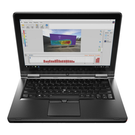
Soft dB Piccolo-II User manual

Piccolo-II
Integrating Averaging Sound Level Meter
User Guide V1.1.0 – 2018/01/29
Soft dB Inc.
1040,
Belvedere Avenue, Suite 215
Quebec (Quebec) Canada G1S 3G3
Toll free: 1
-866-686-0993 (USA and Canada)
E-mail: info@softdb.com

i
Contents
1Introduction............................................................................................................................. 1
1.1 Features ........................................................................................................................................................... 1
2First Use.................................................................................................................................... 2
2.1 Unpacking....................................................................................................................................................... 2
2.2 Instrument Components........................................................................................................................... 2
2.3 Dimensions..................................................................................................................................................... 3
2.4 Buttons............................................................................................................................................................. 3
2.5 Display Screen ............................................................................................................................................... 4
2.6 Overload Indication..................................................................................................................................... 4
2.7 Power-Up ........................................................................................................................................................ 5
2.8 Shut-Down...................................................................................................................................................... 5
3Running a Measurement......................................................................................................... 6
3.1 Single-Store.................................................................................................................................................... 6
3.2 Auto-Store....................................................................................................................................................... 7
4Data Display............................................................................................................................. 8
5Measurement Setup................................................................................................................ 9
6Calibrating ............................................................................................................................. 10
7Locking and Unlocking ......................................................................................................... 11
8Software................................................................................................................................. 12
8.1 Download and Install................................................................................................................................12
8.2 First Use .........................................................................................................................................................12
8.3 Memory Download....................................................................................................................................13
8.4 Records Viewer............................................................................................................................................13
8.5 Spectrum Analyzer ....................................................................................................................................15
8.6 Calibration ....................................................................................................................................................16
8.7 Calibration Certificate...............................................................................................................................16
8.8 Audio Recording.........................................................................................................................................17
8.9 Clock Synchronisation..............................................................................................................................17

ii
9Technical Specifications........................................................................................................18
10 Measuring to IEC 61672-3.....................................................................................................20
10.1 Calibration ....................................................................................................................................................20
10.2 Inserting Electrical Signals ......................................................................................................................20
10.2.1 Adjusting Sensitivity for the Auxiliary Input......................................................................20
10.3 Reference Dynamic Range......................................................................................................................20
10.4 Corrections ...................................................................................................................................................21
10.4.1 Specifications Adjustment.......................................................................................................21
10.4.2 Pressure Response ......................................................................................................................21
10.4.3 Effect of Windscreen ..................................................................................................................21
10.4.4 Directional Response .................................................................................................................22
11 Glossary..................................................................................................................................23
12 Specimen Calibration Certificate ......................................................................................... 25
13 Warranty ................................................................................................................................ 29

1
1Introduction
Congratulations for purchasing the Piccolo-II Integrating Sound Level Meter. This instrument
provides an innovative and cost effective solution for professional grade acoustical measurement.
1.1 Features
•Precision Integrating Sound Level Meter;
•A, C and Z simultaneous frequency weightings;
•Leq, Lmax, Lmin, Lpeak, SEL and 7 LN% (L1%, L5%, L10%, L50%, L90%, L95% and L99%);
•Large dynamic range: 30 dBA to 130 dBZpk1;
•Slow or Fast SPL Time response;
•1/1 Octave spectrum;
•1/3 Octave spectrum2;
•400 lines FFT spectrum;
•16 MB memory for up to 214 252 records;
•Auxiliary input for external microphone;
•Large Li-Ion battery for up-to 48h operating time.
1Using two ranges: Low : 30 dBA to 110 dBpk, High 46 dBA to 130 dBpk, at nominal sensitivity
21/3 octave spectrum available using software

2
2First Use
2.1 Unpacking
2.2 Instrument Components
Carrying Case
USB Cable
Piccolo-II Instrument
Calibration Certificate
Display
Buttons
Overload
LED
USB
Connector
Charging
LED
Auxi Jack (1/8)
Reset
Button
Tripod
Adapter
(1/4-20)
SN Label
Microphone

3
2.3 Dimensions
2.4 Buttons
There are 3 buttons on the Piccolo-II to control the instrument. Icons displayed above each button
indicate the functions associated with a long-press and icons under the buttons indicate the
functions associated with a short-press.
144mm (5 5/8”)
59mm (2 5/16”)
18.5mm (23/32”)
13.2mm (0.52”)
“Short
-Press” Functions
Change
Data Display
Run/Stop “Single
-Store” Measurement
Measurement Setup Select
“Long
-Press” Functions
Measurement Setup
Run/Stop “Auto
-Store” Measurement
Power ON/OFF

4
2.5 Display Screen
1) Battery Level (contour blinking when charging)
2) Maximum Sound Pressure Level (SPL)
3) Minimum SPL
4) Average in progress (blinking)
5) Equivalent Level
6) Live SPL Bar Graph (Right-most segment blinking on Under-Range, Left-most segment
blinking on Over-Load)
7) SPL Time-Weight (Fast or Slow)
8) dB Units
9) Frequency Weighting (A, C or Z)
10) Sound Level (Live SPL, Leq, Lmax, Lmin, SEL, Lpeak;
Record Number;
Elapsed Time (mm:ss);
Overload (- or 1);
Battery %.
11) Additional Label: SPL, SEL, PEA (Lpeak), rEC (Record number), bAtt (Battery);
Under-Range (- or 1);
12) Time indicator: visible when displaying Elapsed Time.
2.6 Overload Indication
The overload LED will blink for 1s when an overload occurs. If the overload occurs
during a measurement, the right-most segment of the SPL Bar Graph will blink.
This segment will keep blinking until another measurement is performed.
The overload threshold is set 1 dB below the upper limit of the dynamic range.
1
2
3
4
5
6
7
9
8
10
11
12

5
2.7 Power-Up
To power ON the instrument, press and hold the right-most button. At power-up, the display
screen displays the live SPL.
To power-up the instrument, perform a long-press on the right-
most button. This
will power-up the instrument and display “Init” on the display during the warm-up
process (~1s).
2.8 Shut-Down
To shut-down the instrument, press and hold the right-most button until the display turns off.
When no measurement is in progress, the instrument will shut-down after 10 minutes of inactivity.
Long-Press

6
3Running a Measurement
There are two measurement modes available on the Piccolo-II: “Single-Store” and “Auto-Store”.
The Single-Store runs a single average period and stopes after the specified duration or when the
user stops the measurement.
The Auto-Store runs a series of average periods one after the other until the user stops the
measurement or until the memory is full.
3.1 Single-Store
To start a Single-Store measurement, perform a short-
press on the center button.
This will display “run SGLE” on the display for 1s and start the measurement.
Once the measurement is started, the display automatically shows the Leq.
While the measurement is running, the “Avg” indicator will blink and the left-most
segments will rotate indicating a measurement in progress.
To stop the measurement, perform a short-
press on the center button or simply
wait for the measurement duration to be elapsed.
When the measurement is over, the record number will be displayed for 1s and the
display will return to the Leq.
Short-Press
Short-Press

7
3.2 Auto-Store
To start an Auto-Store measurement, perform a long-press on the center button.
This will display “run AUTO” on the display for 1s and start the measurement.
Once the measurement is started, the display automatically shows the Leq.
While the measurement is running, the “Avg” indicator will blink and the left-most
segments will rotate indicating a measurement in progress.
Note that the left-most segments rotate to form an “O” shape in Auto-Store mode
whereas it forms a small “o” shape in Single-Store mode.
To stop the measurement, perform a short-press on the center button or simply
wait for the measurement duration to be elapsed.
When the measurement is over, the record number will be displayed for 1s and the
display will return to the Leq.
Long-Press
Long-Press

8
4Data Display
Each Data Display is accessible by performing a short-press on the right-most button. This will flip
through the following displays:
Live SPL : Live sound pressure level
Leq : Equivalent sound level of the last record
Lmax : Maximum SPL of the last record
Lmin : Minimum SPL of the last record
SEL : Sound Exposure Level of the last record
Lpeak : Peak sound level of the last record
Record : Number of the last record
Time : Duration of the last record
Dynamic Info : Overload and Under-Range indicators of the last record
Battery : Battery percent

9
5Measurement Setup
The measurement setup is accessible by performing a long-press on the left-most button. Another
long-press on the button changes the setup menu and a short-press on the button changes the
parameter value. To exit the menu, click on any of the two other buttons or wait 10s.
Record Duration : Flips through 1s, 10s, 1m, 5m, 15m and 60m. Note that these
durations can be changed using the software.
Calibration : Flips through 94 dB or 114 dB calibrator selection. A long-press on the
center button starts the calibration process. Refer to section XX for more information.
Input Range : Flips through “Low” and “High”. Refer to technical specifications for more
information on the input range.
Frequency Weighting : Flips through “A”, “C” and “Z” frequency weighting to display.
Note that “A”, “C” and “Z” global levels are always recorded regardless of this parameter.
The only exception are percentiles (LN%) which are only recorded for the selected
frequency weighting.
SPL Time Response : Flips through “Fast” and “Slow” time response for sound pressure
level exponential response.
FFT Mode : Flips through “On” and “Off” to record or not record the FFT spectrum.

10
6Calibrating
1) Insert the microphone in the calibration chamber of a microphone calibrator1
2) Perform a long press on the Setup button to enter the setup;
3) Perform another long-press on the setup button to get to the calibration menu;
4) Perform a short-click on the setup button to select the calibration level (94dB or 114 dB)
matching the calibrator reference level;
5) Turn the calibrator ON;
6) Perform a long-press on the RUN/STOP button to initiate the calibration process;
7) The calibration process takes 5s. During this period the display shows the measured SPL
and the “Avg” label blinks;
8) When the process is done, the display shows “done” indicating a success or “err” indicating
an error.
An error can occur if the calibration value is out of range. This can occur when the calibrator is not
in function or when the level selection (94-114) does not match the calibrator reference level.
Note that when an external signal source is connected on the auxiliary jack, the auxiliary input will
be calibrated. This will not affect the calibration value of the main microphone.
The calibration process can also be performed using the software. Refer to section 8.6 for more
information.
1The microphone calibrator should be compliant to IEC 60942.

11
7Locking and Unlocking
To lock and unlock the Piccolo-II, press and hold all 3 buttons at the same time. When the
instrument gets locked or unlocked, it will display the following:
Locked
Unlocked

12
8Software
8.1 Download and Install
To download the software installer, use the following link:
www.softdb.com/software.php?piccolo-2
Computer Requirements
Item Minimum Requirements
Operating System Windows 7 or more
CPU Dual-Core at1.2 GHz
Memory 2 GB RAM
Hard drive 300 MB free hard disk space
Port USB 2.0
Display resolution 800 x 600
8.2 First Use
1) To open the software, click on “Piccolo-II” from the Start Menu.
2) Connect a Piccolo-II instrument to the computer using the provided USB cable. Once
connected, the software should automatically detect it.

13
The left side of the interface shows the Instrument Panel and the right side shows the Setup and
Tools.
The Instrument Panel shows exactly what’s happening on the instrument itself. You can use the 3
software buttons as you would with the physical buttons. The display screen shows the same
information as on the physical instrument as well as the Overload LED.
The Setup and Tools shows the setup parameters of the instrument as well as additional tools
8.3 Memory Download
1) Click on the “Load” button to load the records in memory;
2) Once the download is completed, the “Records Viewer” interface will be launched.
8.4 Records Viewer
The “Records Viewer” function allows viewing recorded measurements data, save it to a file and
export it to a text file.
Upon downloading data from a Piccolo-II instrument, this record viewer will automatically open.
When used as a post-processing viewer, click on the “Open” button to load a record file.
Setup and Tools
Instrument Panel

14
The main interface shows a time history graph of all recorded measurements. You can add a data
plot by clicking on the “Add Plot” button.
Drag the cursor on the graph to update the legend values.
You can zoom in/out on the graph using the magnifier buttons or using the mouse wheel or the
up/down keys.
You can move the time range by moving the scrollbar at the bottom, or by dragging the cursor on
the graph limits or by using the left/right keys.
Click on the “Show Details” button to open the record details panel. This panel shows the details of
the record indicated by the cursor. Moving the cursor on the time history graph updates the
displayed information.
Click on “View List” to show the recorded measurements as a table. When displaying the list, click
on “View Graph” to go back to the time history graph. Note that displayed data curves on the time
history graph will appear as data columns in the list view. The selected row in the list is linked to
the cursor on the time history graph

15
Click on the “Save” or “Save As” button to save the records in a *.pic2 file.
Click on the “Export” button to export the data in a tab delimited file.
8.5 Spectrum Analyzer
The Spectrum Analyzer function allows to record 1/1 octave, 1/3 octave and FFT records
simultaneously. All spectra definitions are recorded simultaneously.
1) Click on the “Spectrum Analyzer” button to launch the spectrum analysis tool;
2) Click on the “Start” button to start a measurement;
3) Click on the “Stop” button to stop the measurement.
Live or Averaged spectrum can be displayed using the drop-down menu on the right.
The spectrum definition (1/1 octave, 1/3 octave or FFT) is selected using the drop-down menu on
the right.
The measured spectrum can be saved to a *.sp2 file which can be opened using the same tool.

16
8.6 Calibration
1) Click on the “Calibration” button to launch the microphone calibration interface;
2) Insert the microphone in the calibration chamber of a microphone calibrator1;
3) Enter the calibrator reference Sound Pressure Level and Frequency;
4) Turn the calibrator ON;
5) Click on the “Start” button to start the calibration process;
6) After 5s the measurement stops and the sensitivity value is updated.
Note: If an external source is used with the auxiliary jack connector, the auxiliary jack will be
calibrated.
8.7 Calibration Certificate
Click on the “Certificate” button to view the factory calibration certificate of the Piccolo-II:
1The microphone calibrator should be compliant to IEC 60942.

17
Each Piccolo-II instrument is calibrated and tested at the factory following the procedures from IEC
61672-3 (2013) / ANSI/ASA S1.4-3 (2014) Electroacoustics – Sound Level Meters – Part 3: Periodic
Tests.
A paper copy of the calibration certificate is delivered with each instrument and the certification
data is stored in the instrument internal memory for software display. The Piccolo-II instruments
can be sent back to the factory for periodic testing. Contact info@softdb.com for more information.
Refer to section 12 for a specimen calibration certificate.
8.8 Audio Recording
1) Click on the “Audio Recording” to launch the audio recording tool;
2) Click on the “Start” button to start a recording;
3) Click on the “Stop” button to stop the recording;
4) Upon stopping the recording, the software prompts to save the recorded file.
On the audio recording interface, the graph shows the time signal and the vertical fill-bar shows
the dynamic range.
If an external source is used with the auxiliary jack connector, the auxiliary jack will be used as the
signal source to be recorded.
8.9 Clock Synchronisation
Click on the button to synchronize the clock with the computer clock.
When the Piccolo-II clock indicates an offset of more than 10s compared to the computer clock,
this icon will be displayed next to the clock in the software interface.
Table of contents
Other Soft dB Measuring Instrument manuals
