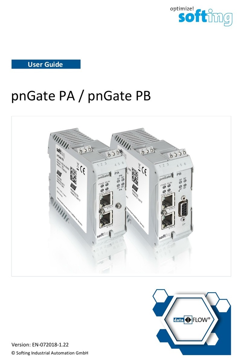
Softing pnGate PA User manual

© Copyright 2014 - 2016 Softing Industrial Automation GmbH
pnGate PA
User Manual
Version: EN-072016-1.01

The information contained in these instructions corresponds to the technical status at the time of printing of it and is passed on with the
best of our knowledge. The information in these instructions is in no event a basis for warranty claims or contractual agreements
concerning the described products, and may especially not be deemed as warranty concerning the quality and durability pursuant to Sec.
443German Civil Code. We reserve the right to make any alterations or improvements to these instructions without prior notice. The
actual design of products may deviate from the information contained in the instructions if technical alterations and product
improvements so require.
It may not, in part or in its entirety, be reproduced, copied, or transferred into electronic media.
Disclaimer of liability
Softing Industrial Automation GmbH
Richard-Reitzner-Allee 6
85540 Haar / Germany
http://industrial.softing.com
The latest version of this manual is available in the Softing download area at: http://industrial.softing.com/en/downloads.html
+ 49 89 4 56 56-0
+ 49 89 4 56 56-488
info.automation@softing.com
support.automation@softing.com

Copyright 2016 Softing Industrial Automation GmbH 3
Table of Contents
Table of Contents
Chapter 1 ...................................................................................... 5
Introduction
............................................................................................................... 51.1 About pnGate PA
............................................................................................................... 61.2 Intended use
............................................................................................................... 61.3 Scope of delivery
............................................................................................................... 71.4 Conventions used
............................................................................................................... 71.5 Safety precautions
............................................................................................................... 71.6 Supported features
............................................................................................................... 71.7 System requirements
............................................................................................................... 81.8 Document history
Chapter 2 ...................................................................................... 9
PROFINET - organization and specifications
Chapter 3 ...................................................................................... 10
Introduction to PROFIBUS PA
Chapter 4 ...................................................................................... 12
Installation
............................................................................................................... 124.1 Install hardware
.......................................................................................................... 12
Mounting and dismounting4.1.1
.......................................................................................................... 13
Connection diagram4.1.2
.......................................................................................................... 13
Connecting the power supply4.1.3
.......................................................................................................... 14
Connect to network4.1.4
.......................................................................................................... 14
Power up the device4.1.5
.......................................................................................................... 14
Ethernet ports4.1.6
............................................................................................................... 154.2 User application scenarios
............................................................................................................... 154.3 Install software setup files
Chapter 5 ...................................................................................... 17
Commissioning
............................................................................................................... 175.1 Preconditions
............................................................................................................... 175.2 Avoid IP address conflict
............................................................................................................... 175.3 Application scenario PROFINET commissioning
.......................................................................................................... 17
Generate import file5.3.1
.......................................................................................................... 18
Create new project in Siemens TIA portal5.3.2
............................................................................................................... 245.4 Application scenario DTM parameterization
.......................................................................................................... 25
Detect and modify IP addresses with Search and Configure5.4.1
.......................................................................................................... 26
Configure CommDTM5.4.2
.......................................................................................................... 26
Access device DTMs5.4.3
..................................................................................................... 26
Set IP address
5.4.3.1
..................................................................................................... 27
Configure PROFIBUS driver
5.4.3.2
..................................................................................................... 28
Establish a connection in PACTware
5.4.3.3

Copyright 2016 Softing Industrial Automation GmbH
Table of Contents
4
Chapter 6 ...................................................................................... 30
Status indicators - LEDs
............................................................................................................... 306.1 PWR - power supply
............................................................................................................... 316.2 Device LED statuses (PWR, RUN, ERR and CFG) in stand-alone mode
............................................................................................................... 326.3 PROFINET device LEDs (PN)
............................................................................................................... 326.4 PROFIBUS master LEDs (PA)
Chapter 7 ...................................................................................... 33
Using the internal webserver interface
............................................................................................................... 337.1 Login to webserver
............................................................................................................... 337.2 Read version information
............................................................................................................... 347.3 Change password
............................................................................................................... 347.4 Update firmware
Chapter 8 ...................................................................................... 36
If you are using more than one network adapter
Chapter 9 ...................................................................................... 38
Technical data
............................................................................................................... 389.1 specifications
............................................................................................................... 389.2 Installation position and related ambient operating temperature TA
Chapter 10 ...................................................................................... 41
Declarations by the manufacturer
Index ................................................................................................................ 43

Chapter 1 - Introduction
Copyright 2016 Softing Industrial Automation GmbH 5
1Introduction
Read this manual before starting
For damages due to improper connection, implementation or operation Softing refuses any
liability according to our existing warranty obligations.
1.1 About pnGate PA
pnGate PA is a two channel host interface that provides access to PROFIBUS PA networks. It combines two
devices in a single one – a PN/DP Gateway and a DP/PA coupler. It is using PROFINET and is used in
systems with PROFINET controllers in process industries. In addition it is applied in controller upgrade
scenarios instead of DP/PA couplers.
pnGate PA can be operated with the following commonly used tools:
PROFINET engineering systems (e.g. Siemens TIA Portal)

pnGate PA - User Manual
6Copyright 2016 Softing Industrial Automation GmbH
FDT-based device parameterization
PROFIBUS PA and PROFIBUS DP devices come along with GSD files for use in PROFIBUS engineering
systems. PROFINET devices are delivered with GSDML files instead of GSD files. Therefore the PA devices
GSDs have to be converted into a GSDML format. Compared with engineering PA devices in PROFIBUS
Masters, our conversion tool is the only additional tool that needs to be used to engineer PA devices in a
PROFINET Controller environment when using the pnGate PA.
1.2 Intended use
pnGate PA is a gateway between PROFINET and PROFIBUS PA devices.
CAUTION
The unit must not be used in explosion hazard areas. The permissible ambient conditions given
in Chapter Technical data must be complied with.
Note
Faultless and safe operation of the product requires proper transport, proper storage and
installation, and expert operation and maintenance in accordance with the manual.
Note
If the notes stated in this document are not observed or in case of inappropriate handling of
the device, our liability is waived. In addition, the warranty on devices and spare parts does no
longer apply.
For information about safety aspects refer to Safety precautions .
1.3 Scope of delivery
The pnGate PA comprises the following parts:
pnGate PA device,
CD-ROM including drivers, software, tools and manuals,
Quick Startup Guide.
Two product variants
The pnGate PA exists in two variants. They only differ in their installation position rotated by
180° including the corresponding rotated front panel and LED layout.
38
7

Chapter 1 - Introduction
Copyright 2016 Softing Industrial Automation GmbH 7
1.4 Conventions used
The following conventions are used throughout Softing customer documentation:
Keys, buttons, menu items, commands and other
elements involving user interaction are set in
bold font and menu sequences are separated by
an arrow
Open Start Control Panel Programs
Buttons from the user interface are enclosed in
brackets and set to bold typeface
Press [Start] to start the application
Coding samples, file extracts and screen output is
set in Courier font type
MaxDlsapAddressSupported=23
Filenames and directories are written in italic
Device description files are located in C:
\<Application name>\delivery\software
\Device Description files
CAUTION
CAUTION indicates a potentially hazardous situation which, if not avoided, may result in minor
or moderate injury.
Note
This symbol is used to call attention to notable information that should be followed during
installation, use, or servicing of this device.
Hint
This symbol is used when providing you with helpful user hints.
1.5 Safety precautions
CAUTION
During operation, the device's surface will be heated up. Avoid direct contact. When servicing,
turn off the power supply and wait until surface has cooled down.
Note
Do not open the housing of the pnGate PA. It does not contain any parts that need to be
maintained or repaired. In the event of a fault or defect, remove the device and return it to
the vendor. Opening the device will void the warranty!
1.6 Supported features
This version of the pnGate PA allows integration of PA devices into PROFINET engineering systems by
converting the GSD files of PA devices into a single GSDML file. This conversion can deliver exclusively
device parameters that are described in the GSD in the first place.
The number of segments supported in this version is two.
The number of devices supported per segment in this version is 16.
1.7 System requirements
When using the gateway, a PROFINET engineering system such as TIA portal, STEP 7 starting with version
5.5 SP 4, is required (see also Create new project in Siemens TIA portal ).
18

pnGate PA - User Manual
8Copyright 2016 Softing Industrial Automation GmbH
1.8 Document history
Document
version
Modifications compared to previous version
1.00
Initial version - no modifications.
1.01
New Corporate Identity implemented.

Chapter 2 - PROFINET - organization and specifications
Copyright 2016 Softing Industrial Automation GmbH 9
2PROFINET - organization and specifications
The different aspects of a PROFINET system (communication protocol, device description, profiles,
installation guidelines, etc.) are defined in different specifications. PROFINET specifications are created by
the respective workgroups established by PROFINET International (PI). PI members can download the
specifications from the website www.profinet.com. PI has about 1,400 members worldwide. The majority
of specifications have been submitted to the applicable international standardization bodies.
Specification
Int. Standard
Topic
PN IO V 2.3
IEC 61158, Ed. 4
Digital data communications for measurement and
control - Fieldbus for use in industrial control systems
RT/IRT
IEC 61784-2
Digital data communications for measurement and
control. Profile sets – Part 2
GSDML V 2.32
ISO 15745
Industrial automation systems and integration -- Open
systems application integration framework
PN Security
IEC 62443
Security Aspects of Distributed Industrial Computer
Systems
IEC 61784-4
Digital data communications for measurement and
control. Profile sets – Part 4
PROFINET Cabling and
Inter-connection
IEC 61918
Digital data communications for measurement and
control – Profiles covering installation practice for
fieldbus communications media within and between
the Automation Islands
IEC 61784-5
Digital data communications for measurement and
control. Profile sets – Part 5
Profile for Process
Control devices V3.02
Base set of device parameters for operation,
commissioning, maintenance, diagnosis and a
mechanism to achieve connectivity of parameters
defined by user groups and device vendors.
This document includes the "Amendment 1, PROFIsafe
for PA Devices, Version 1.01"

pnGate PA - User Manual
10 Copyright 2016 Softing Industrial Automation GmbH
3Introduction to PROFIBUS PA
PROFIBUS (PROcess FIeld BUS) is a world leading fieldbus communication standard in automation
technology. It is designed for digital data exchange within a network using a single bus cable and achieves a
high data transmission reliability. Based on different related application profiles, it provides solutions for a
wide range of application areas including manufacturing and process automation (see figure below).
The capabilities of individual PROFIBUS field devices are described by the General Station Description (GSD)
files, supplemented by the Electronic Device Description (EDD) files. The GSD file contains the key data of
an individual PROFIBUS slave, information about its communication capabilities and, e.g. diagnostic values.
It supplies all information necessary for the cyclic exchange of measured values and calculated variables
between the field device and the PROFIBUS master, and supports the configuration of the PROFIBUS
network. The EDD file provides additional information describing application-specific functions and the
parameters of complex field devices. It comprises a description of acyclically communicated device
capabilities, including graphics-based options, and device information such as order data, materials,
maintenance instructions, etc.
In 1996, the first PROFIBUS Process Automation (PA) application profile was released (current version is
3.02, released in April 2009). It uses the PROFIBUS DP communication technology and especially addresses
process automation needs. PROFIBUS PA is suitable for use in hazardous and potentially explosive areas
(Ex zones 0 and 1). In addition to supporting the standard PROFIBUS DP transmission technology RS485,
PROFIBUS PA can also perform the data transfer based on Manchester Coded Bus Powered (MBP), which is
capable of supplying power to the individual field devices via the bus wire.
As a consequence, the wiring overhead can be reduced significantly. MBP communication requires only
8Bits for encoding a character. Thus, PROFIBUS PA meets the requirements for a much simpler and safer
installation and boasts all the benefits of digital transmission right down to the field device. PROFIBUS PA
also supports intrinsically safe applications providing explosion protection by limiting the power supplied
by the bus or the installation components in the field. It is widely used in chemical, oil, and gas industry
applications. The MBP transmission technology basically supports a variety of different topologies,
including linear and simple tree structures. In practice, the „Trunk & Spur Topology“ (see figure below) has
established itself as the de-facto standard, as it is particularly clear and well laid out. Thanks to the
technically mature installation technologies available on the market, it also exhibits a high degree of
robustness. The overall length of a segment may not exceed 1,900m, and the length of the spurs in
intrinsically safe applications is limited to 30m and must be taken into account when calculating the overall
length.

Chapter 3 - Introduction to PROFIBUS PA
Copyright 2016 Softing Industrial Automation GmbH 11
Trunk & Spur Technology Used by PROFIBUS PA and Coupling of PROFIBUS PA Segments to PROFIBUS DP
PROFIBUS PA is based on the PROFIBUS DP-V1 version. It uses the PROFIBUS DP protocol at a data
transfer rate of 31.25Kbit/s and is connected to a PROFIBUS DP network using a coupling device.
PROFIBUS DP then acts as a backbone network for transmitting process signals to the controller.
The PROFIBUS PA application profile defines functions and parameters for process control devices, such as
transmitters, actuators, valves, and analyzers. These functions and parameters are used to adapt the
devices to the respective application and process conditions. The functions are based on Function Blocks,
and the associated parameters are classified as input, output, and internal parameters. The PROFIBUS PA
application profile also determines how the various services of the PROFIBUS communication protocol are
used. This means, for example, that process data that is exchanged cyclically is based on a standard format
for all devices. In addition to the measured value and/or manipulated measurement value, this format also
features a status supplying information about the quality of the value and possible limit violations. It
thereby provides the foundation for harmonized applications, simplified engineering, device
exchangeability and increased reliability by means of standardized diagnostic information.
The latest version V3.02 of the PROFIBUS PA application profile especially addresses user requests for
comprehensive diagnostic and status information as well as the requirements of system-oriented asset
management for field devices within process automation applications.

pnGate PA - User Manual
12 Copyright 2016 Softing Industrial Automation GmbH
4Installation
4.1 Install hardware
Note
If ambient temperatures exceed 55 °C at the place of installation, it may occur that the
temperatures of connecting cables strongly rise if those cables have been put in place in an
unfavorable condition. In such cases, either perform measurements to confirm that the
service temperature of the cables is not exceeded (i.e. 80 °C), or use such variants that
withstand temperatures of minimum 90 °C.
4.1.1 Mounting and dismounting
Note
Make sure the pnGate PA is mounted in a manner that the power supply disconnecting device
or interrupt facility can always be reached easily.
Note
Depending on the installation position, the maximum ambient operating temperature may
differ. Refer to Technical Data for detailed information.
Installation and inspection
Installation and inspection tasks are to be carried out by qualified personnel only, i.e.
personnel qualified according to TRBS 1203 or similar! The definition of terms can be found in
IEC 60079-17.
Mounting
1. For mounting the pnGate PA on a DIN rail (35 mm), attach the two upper notches to the rail.
2. Press the device down towards the rail until it locks into place.
Note
Do not put stress on the system by bending or torsion.
Dismounting
To dismount the pnGate PA from the DIN rail, slide a screw driver horizontally underneath the housing into
the locking bar, slide the bar downwards – without tilting the screw driver - and fold the device upwards.
38

Chapter 4 - Installation
Copyright 2016 Softing Industrial Automation GmbH 13
4.1.2 Connection diagram
The following connection diagram gives an overview about the different plugs and interfaces:
4.1.3 Connecting the power supply
1. Connect the PROFIBUS PA channels to the terminal blocks of the PROFIBUS PA interfaces.
Note
Since the device does not provide power to the PROFIBUS PA links, a power supply, a
power conditioner and a bus termination is required for each PROFIBUS PA channel.
2. Connect the device to a 24 V DC power supply.
The supply voltage (18 VDC .... 32 VDC) is connected by a 3-pole terminal block. The power supply is
connected to the plug connector via flexible wires with a cross section of 0.75 to 1.5 mm². The ground
connection wire must have a cross section of 1.5 mm².
Pin
Signal
Description
3
L+
Positive supply voltage
2
Functional earth
1
GND
Ground
CAUTION
The Functional Earth (FE) connection of the device has to be connected at low inductance with
the Protective Earth (PE) of the system.
Note
As indicated in the connection diagram, the power can be applied alternatively by a special DIN
rail connector (Rail Power Supply). For further information contact Softing Industrial
Automation GmbH.

pnGate PA - User Manual
14 Copyright 2016 Softing Industrial Automation GmbH
4.1.4 Connect to network
1. Connect the PROFIBUS PA channels to the terminal blocks of the PROFIBUS PA interfaces.
2. Connect the pnGate PA to the PROFINET network. The pnGate PA includes a PROFINET switch that
enables line topology.
4.1.5 Power up the device
Turn on the power supply. The boot process takes approx. 15 seconds. For indication of proper operation
refer to Status indicators - LEDs .
4.1.6 Ethernet ports
The pnGate PA is equipped with two 10/100 Base-T Ethernet interface receptacle (RJ45). Both ports are
connected to the switch. The Ethernet ports corresponds to the IEEE 802.3 with the pin assignment shown
below.
Ethernet Port 1 (ETH 1):
Pin
Signal
Description
1
TX+
Transmit signal positive
2
TX-
Transmit signal negative
3
RX+
Receive signal positive
4
Not used
Drain wire
5
Not used
Drain wire
6
RX-
Receive signal negative
7
Not used
Drain wire
8
Not used
Drain wire
30

Chapter 4 - Installation
Copyright 2016 Softing Industrial Automation GmbH 15
Ethernet Port 2 (ETH 2):
Pin
Signal
Description
1
TX+
Transmit signal positive
2
TX-
Transmit signal negative
3
RX+
Receive signal positive
4
Not used
Drain wire
5
Not used
Drain wire
6
RX-
Receive signal negative
7
Not used
Drain wire
8
Not used
Drain wire
4.2 User application scenarios
Installation when using devices for cyclical data exchange in PROFINET
If you intend to bring your devices in cyclical data exchange with a PROFINET controller, then
1. install the gsd-to-gsdml conversion tool for converting gsd files into a single gsdml file as described in
Install software setup files ,
2. convert your gsd files into a single gsdml file as described in Generate import file ,
3. import the file into a new or an existing TIA project as described in Create new project in Siemens TIA
portal and
4. import the device into a project and set slave address and channel as described in Commissioning .
Installation when performing PA parameterization with FDT
If you intend to parametrize your PA devices, then
1. install all tools from your CD ROM as described in Install software setup files ,
2. perform the FDT parametrization as described in Application scenario DTM parameterization ,
3. perform the PROFINET commissioning (select segment and assign an address) as described in
Commissioning .
4.3 Install software setup files
Note
If you install a Softing product for the first time, a window is opened that prompts you to trust
the publisher. Activate the option Always trust software from Softing AG, if you do not want
to be asked in subsequent installations. Then select [Install] to start the installation.
1. Insert your pnGate PA CD-ROM into your CD drive.
a. If Autorun is enabled on your system, the startup page is opened.
b. If Autorun is disabled, open an Explorer window, select your CD drive and double-click the file
start.exe in the CD's root directory.
15
17
18
17
15
24
17

pnGate PA - User Manual
16 Copyright 2016 Softing Industrial Automation GmbH
2. From the startup select the installation setup files required:
a. GSDtoGSDML-Converter to allow converting gsd files into a single gsdml file, see Generate import
file ,
b. SearchAndConfigure, required to detect and modify device IP addresses, see Detect and modify IP
addresses with Search and Configure . If you have assigned an IP address you may need to
modify the default password, see Login to webserver .
c. PACTware, if no other FDT frame application is used. After starting the setup file, you are prompted
to select the relevant components. Softing PROFIdtm V2.20 is required. To accelerate the setup
you may deactivate all other dtms.
Hint
If you prefer using another frame application such as FieldCare, FieldMate or others, then
select the separate PROFIdtm installation to install the PROFIdtm without installing
PACTware and to allow using a CommDTM in another FDT frame application. Then follow
the steps described in Configure CommDTM .
17
25
33
26

Chapter 5 - Commissioning
Copyright 2016 Softing Industrial Automation GmbH 17
5Commissioning
5.1 Preconditions
You have the GSD files for your devices available.
The conversion tool (GSDtoGSDML-converter.exe) is installed.
The PROFIBUS devices have already been put into operation.
5.2 Avoid IP address conflict
To make the PROFINET communication working properly ensure that you do not use the same IP address
in the PROFINET engineering system (e.g. TIA portal) that you are using in the devices web server. Thus you
avoid an IP address conflict.
5.3 Application scenario PROFINET commissioning
5.3.1 Generate import file
1. Double-click the file GSDtoGSDML-converter.exe. The converter tool window is opened.
2. Click [Import], select the desired files and confirm with [Open]. The imported files appear in the left
window part.
3. Highlight the GSD files you want to use for conversion and click the arrow [==>] to copy the GSD files
into the right window part.

pnGate PA - User Manual
18 Copyright 2016 Softing Industrial Automation GmbH
4. Now click [Generate] to start the build.
Note
A maximum of 32 files at a time can be converted into a single GSDML file.
5. After successful conversion a dialog is displayed.
6. Click [Copy to path] to copy the GSDML destination path to your clipboard. Then confirm with [OK].
5.3.2 Create new project in Siemens TIA portal
Open or create a new project in TIA Portal with the PROFIBUS Controller that is used.
1. Start the TIA portal.

Chapter 5 - Commissioning
Copyright 2016 Softing Industrial Automation GmbH 19
2. From the menu select Options, then Manage general station description files (GSD).
3. Import the Gateway GSDML by pasting the source path from your clipboard with Ctrl+V. Then click
[Install].
4. Open the Hardware catalog.
5. In the Hardware Catalog select Other field devices Profinet IO Gateway Softing Industrial
Automation GmbH Softing fieldbus Proxies Softing Fieldbus Access Point.
6. Select Softing pnGate PA.

pnGate PA - User Manual
20 Copyright 2016 Softing Industrial Automation GmbH
7. In the Information dialog select Version to identify the correct GSDML by Date and Time Stamp in
version naming.
8. Then select the gateway, drag it from the Hardware catalog and drop it into the Network View.
9. In Network View click on the link [Not assigned] and select the controller.
Other manuals for pnGate PA
2
Table of contents
Other Softing Recording Equipment manuals
