Softing pnGate PA User manual
© Softing Industrial Automation GmbH
pnGate PA / pnGate PB
User Guide
Version: EN-072018-1.22

The information contained in these instructions corresponds to the technical status at the time of printing of it and is passed on with the
best of our knowledge. The information in these instructions is in no event a basis for warranty claims or contractual agreements
concerning the described products, and may especially not be deemed as warranty concerning the quality and durability pursuant to Sec.
443German Civil Code. We reserve the right to make any alterations or improvements to these instructions without prior notice. The
actual design of products may deviate from the information contained in the instructions if technical alterations and product
improvements so require.
Disclaimer of liability
Softing Industrial Automation GmbH
Richard-Reitzner-Allee 6
85540 Haar / Germany
http://industrial.softing.com
Scan the QR code to find the latest documentation on the product web page under Downloads.
+ 49 89 4 56 56-340
+ 49 89 4 56 56-488
info.idn@softing.com
support.automation@softing.com

Version EN-072018-1.22 3
Table of Contents
Table of Contents
Chapter 1 ...................................................................................... 5
About this guide
............................................................................................................... 51.1 Read me first
............................................................................................................... 51.2 Target audience
............................................................................................................... 51.3 Typographic conventions
............................................................................................................... 61.4 Document history
............................................................................................................... 61.5 Related documentation and videos
............................................................................................................... 61.6 Document feedback
Chapter 2 ...................................................................................... 7
About pnGate PA / pnGate PB
............................................................................................................... 72.1 Intended use
............................................................................................................... 72.2 Scope of delivery
............................................................................................................... 82.3 Supported features
............................................................................................................... 82.4 System requirements
............................................................................................................... 82.5 Safety precautions
Chapter 3 ...................................................................................... 9
Installation
............................................................................................................... 93.1 Hardware installation
.......................................................................................................... 9
Mounting and dismounting3.1.1
.......................................................................................................... 10
Connection diagrams pnGate PA3.1.2
.......................................................................................................... 11
Connection diagram pnGate PB3.1.3
.......................................................................................................... 11
Connecting the power supply3.1.4
.......................................................................................................... 12
Connecting to the network3.1.5
.......................................................................................................... 13
Powering up the device3.1.6
.......................................................................................................... 13
Ethernet ports3.1.7
............................................................................................................... 143.2 Software installation
Chapter 4 ...................................................................................... 16
Configuration
............................................................................................................... 164.1 Prerequisites
............................................................................................................... 164.2 Changing the IP address of the pnGate PA / pnGate PB
............................................................................................................... 184.3 Setting the IP address of the PC
............................................................................................................... 194.4 User roles and permissions
............................................................................................................... 204.5 Login to user interface
............................................................................................................... 214.6 Changing the password
............................................................................................................... 224.7 Updating the firmware
............................................................................................................... 234.8 PROFINET configuration in the TIA Portal
.......................................................................................................... 23
Generating a GSDML import file4.8.1
.......................................................................................................... 24
Creating a new project in Siemens TIA Portal4.8.2

Version EN-072018-1.22
Table of Contents
4
............................................................................................................... 284.9 PROFIBUS parameterization with PACTware
.......................................................................................................... 28
Prerequisites4.9.1
.......................................................................................................... 28
Configuring the PROFIBUS driver4.9.2
.......................................................................................................... 30
Creating a project in PACTware4.9.3
............................................................................................................... 314.10 PROFIBUS parameterization with SIMATIC PDM
.......................................................................................................... 31
Prerequisites4.10.1
.......................................................................................................... 31
Configuring the PROFIBUS driver4.10.2
.......................................................................................................... 31
Connecting the SIMATIC Manager4.10.3
Chapter 5 ...................................................................................... 35
LED status indicators
............................................................................................................... 365.1 Status LEDs (PWR, RUN, ERR and CFG) in stand-alone mode
............................................................................................................... 375.2 PROFINET device LEDs (PN)
............................................................................................................... 375.3 PROFIBUS master LEDs (PA)
Chapter 6 ...................................................................................... 38
Technical data
............................................................................................................... 386.1 Installation positions
Chapter 7 ...................................................................................... 40
Declaration of conformity

Chapter 1 - About this guide
Version EN-072018-1.22 5
1About this guide
1.1 Read me first
Please read this guide carefully before using the device to ensure safe and proper use. Softing does not
assume any liability for damages due to improper installation or operation of this product.
This document is not warranted to be error-free. The information contained in this document is subject to
change without prior notice. To obtain the most current version of this guide, visit the download center on
our website at: http://industrial.softing.com/en/downloads
1.2 Target audience
This guide is intended for experienced operation personnel and network specialists responsible for
configuring and maintaining field devices in process automation networks. Any person using a pnGate PA /
pnGate PB must have read and fully understood the safety requirements and working instructions in this
guide.
1.3 Typographic conventions
The following conventions are used throughout Softing customer documentation:
Keys, buttons, menu items, commands and other
elements involving user interaction are set in
bold font and menu sequences are separated by
an arrow
Open Start Control Panel Programs
Buttons from the user interface are enclosed in
brackets and set to bold typeface
Press [Start] to start the application
Coding samples, file extracts and screen output is
set in Courier font type
MaxDlsapAddressSupported=23
File names and directories are written in italic
Device description files are located in C:
\<Application name>\delivery\software
\Device Description files
CAUTION
CAUTION indicates a potentially hazardous situation which, if not avoided, may result in minor
or moderate injury.
Note
This symbol is used to call attention to notable information that should be followed during
installation, use, or servicing of this device.
Hint
This symbol is used when providing you with helpful user hints.
Video
Dieses Symbol weißt auf ein Video zum entsprechenden Thema hin.

pnGate PA / pnGate PB - User Guide
6Version EN-072018-1.22
1.4 Document history
Document
version
Modifications compared to previous version
1.00
Initial version
1.01
New Corporate Identity implemented
1.10
Applicaction scenario SIMATIC PDM (Chapter 5.5) added
1.20
description and instructions of pnGate PB model added
1.21
corrections and additions of video references
1.22
minor corrections and editorial changes
1.5 Related documentation and videos
The following documents and videos provide additional product information:
Conversion from PROFIBUS GSD to PROFINET GSDML
PROFINET configuration in the TIA Portal
PROFIBUS parameterization in PACTware
PROFIBUS parameterization in SIMATIC PDM
1.6 Document feedback
We would like to encourage you to provide feedback and comments to help us improve the
documentation. You can write your comments and suggestions to the PDF file using the editing tool in
Adobe Reader and email your feedback to support.automation@softing.com.
If you prefer to write your feedback directly as an email, please include the following information with
your comments:
document name
document version (as shown on cover page)
page number
31

Chapter 2 - About pnGate PA / pnGate PB
Version EN-072018-1.22 7
2About pnGate PA / pnGate PB
The Softing pnGate PA / pnGate PB is a PROFINET gateway host interface for integrating PROFIBUS PA and
PROFIBUS DP segment devices in PROFINET systems. Softing offers this gateway for two solutions:
pnGate PA is designed for direct integration of PROFIBUS PA (Process Automation) segments in
PROFINET systems at a fixed speed of 31.2 kbit/s, typically used in areas of process automation with
explosive atmosphere.
pnGate PB offers integration of PROFIBUS DP (Decentralised Peripherals) networks in PROFINET
systems at speeds of up to 12Mbit/s, typically via a centralized controller in factory automation.
Both gateways support industry-standard device configuration, parameterization and condition-monitoring
tools. In addition, the gateways convert GSD files used by PROFIBUS devices to a GSDML file format used
by PROFINET devices.
pnGate PA: two models, two designs
The pnGate PA device is available as 2-channel model and a 4-channel model. Both models come in two
designs. The only difference between these designs is the installation position which is rotated by 180°
(including front panel and the LED position) as shown on the cover. See Chapter Connection diagrams
for more details.
pnGate PA and pnGate PB can be managed with the following tools:
PROFINET engineering systems (e.g. Siemens TIA Portal)
FDT frame application (e.g. PACTware)
Siemens SIMATIC PDM (Process Device Manager)
2.1 Intended use
The PROFINET gateways pnGate PA and pnGate PB are designed to integrate PROFIBUS devices into
PROFINET-based networks.
CAUTION
The unit must not be used in potentially explosive atmospheres. The permissible ambient
conditions specified in Chapter Technical data must be observed.
2.2 Scope of delivery
The following parts are delivered with the pnGate PA / pnGate PB:
pnGate PA / pnGate PB device
CD-ROM containing software applications, manuals and tutorial videos
printed Quick Startup Guide
10
38

pnGate PA / pnGate PB - User Guide
8Version EN-072018-1.22
2.3 Supported features
The pnGate PA / pnGate PB gateways map PROFIBUS devices into PROFINET networks.
pnGate PA can map two or four PROFIBUS PA network segments (with the 2-channel model supporting
up to 32 PROFIBUS devices and the 4-channel model supporting up to 64 PROFIBUS devices).
pnGate PB can map two PROFIBUS PA and one PROFIBUS DP network segments supporting up to 32
PROFIBUS devices.
Both gateways support the conversion of PROFIBUS GSD files into a single PROFINET GSDML using an
integrated web-based conversion tool.
2.4 System requirements
These gateways require the use of a PROFINET engineering system such as the Siemens TIA portal (version
15 or higher) and STEP 7 (version 5.5 SP 4 or higher). Engineering systems from other PLC vendors can also
be used, provided they support PROFINET GSDML files. Further requirements include:
24V power supply
PC with web browser
GSD file for each PROFIBUS device on your network to create a GSDML file for PROFINET configuration
2.5 Safety precautions
CAUTION
During operation, the device's surface will be heated up. Avoid direct contact. When servicing,
turn off the power supply and wait until surface has cooled down.
Note
Do not open the housing of the pnGate PA / pnGate PB. It does not contain any parts that
need to be maintained or repaired. In the event of a fault or defect, remove the device and
return it to the vendor. Opening the device will void the warranty!

Chapter 3 - Installation
Version EN-072018-1.22 9
3Installation
3.1 Hardware installation
Note
With an ambient temperature above 55 °C at the place of installation connecting cables may
heat up strongly if they are installed in an unfavourable position. In such cases, ensure that the
permissible service temperature of the cables (i.e. 80 °C) is not exceeded or use cables
sustaining high temperatures of at least 90 °C.
3.1.1 Mounting and dismounting
Note
Make sure the pnGate PA / pnGate PB is mounted in such a way that the power supply can be
easily disconnected.
Note
Depending on the installation position, the maximum ambient operating temperature may
differ. Refer to Technical data for detailed information.
Installation and inspection
Installation and inspection must be carried out by qualified personnel only (personnel qualified
according to the German standard TRBS 1203 or similar (Technical Regulations for Operational
Safety). The definition of terms can be found in IEC 60079-17.
Mounting
1. For mounting the pnGate PA / pnGate PB on a DIN rail
(35 mm), attach the two upper notches to the rail.
2. Press the device down towards the rail until it locks into
place.
Note
Do not put stress on the system by bending or torsion.
Dismounting
1. Slide a screw driver horizontally underneath the housing into
the locking bar.
2. Slide the bar downwards – without tilting the screw driver -
and fold the device upwards.
38
pnGate PA / pnGate PB - User Guide
10 Version EN-072018-1.22
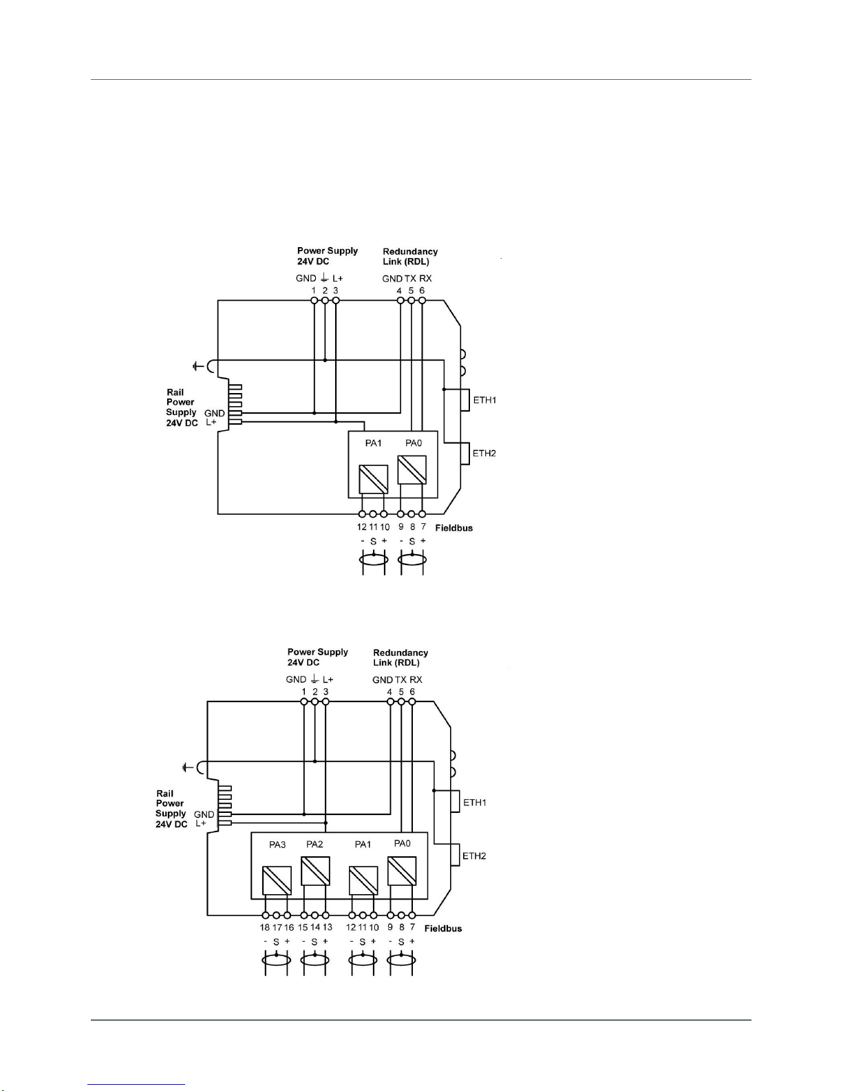
3.1.2 Connection diagrams pnGate PA
The following diagram shows the input and output interfaces of the pnGate PA. The 2-channel model has
2physical PROFIBUS segment connections (PA0 to PA1), while the 4-channel model has 4 physical
PROFIBUS segment connections (PA0 to PA3).
2-channel model
4-channel model
Chapter 3 - Installation
Version EN-072018-1.22 11
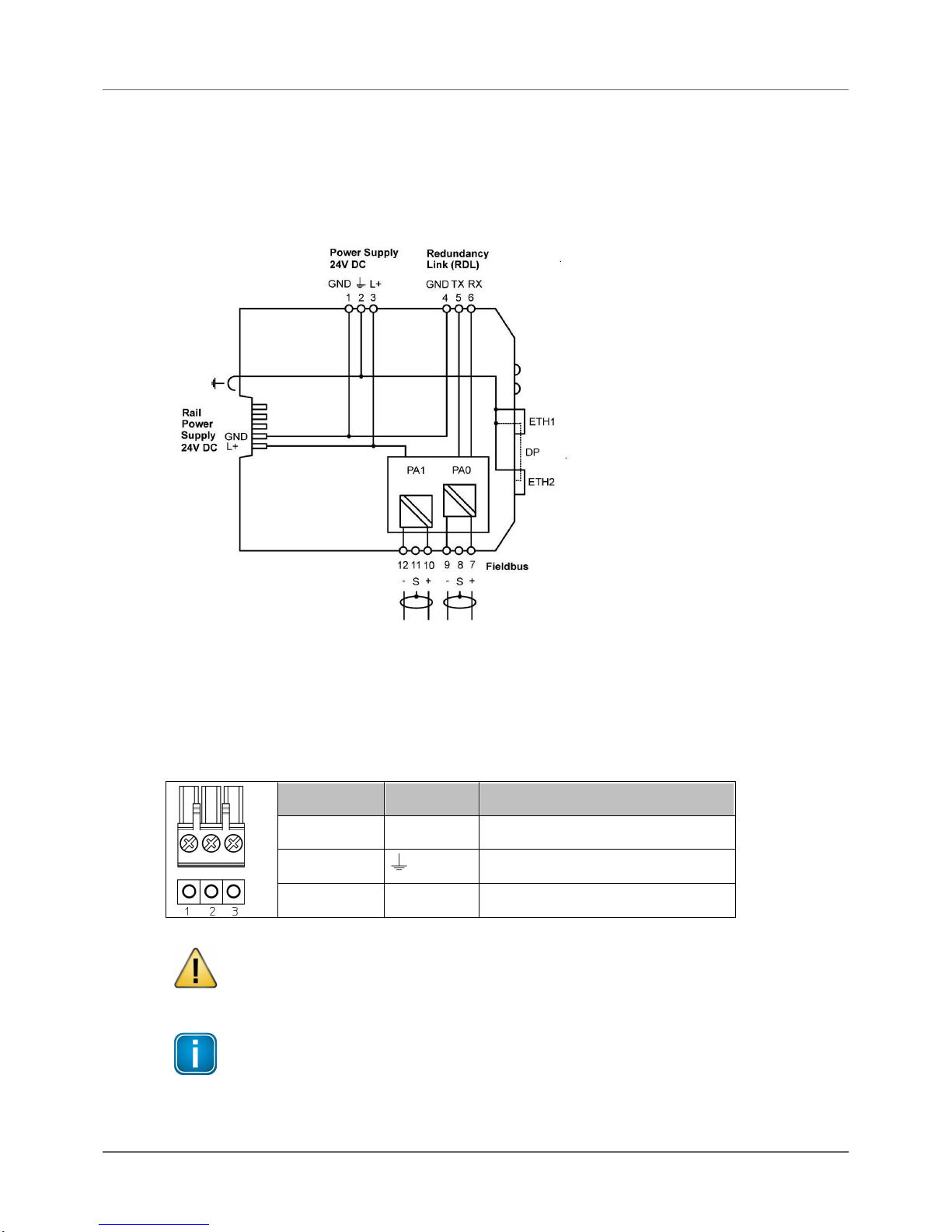
3.1.3 Connection diagram pnGate PB
The following diagram shows the input and output interfaces of the pnGate PB. The gateway has 2 physical
PROFIBUS PA segment connections (PA0 to PA1) and supports on RS-485 link for PROFIBUS DP data
communication.
3.1.4 Connecting the power supply
Connect the gateway to a 24 V DC power supply (not included in the delivery).The supply voltage (18 VDC
.... 32 VDC) is connected by a 3-pole terminal block. The power supply is connected to the plug connector
via flexible wires with a cross section of 0.75 to 1.5 mm². The ground connection wire must have a cross
section of 1.5 mm².
Pin
Signal
Description
1
GND
Ground
2
Functional earth
3
L+
Positive supply voltage
CAUTION
The Functional Earth (FE) connection of the device has to be connected at low inductance with
the Protective Earth (PE) of the system.
Note
As the connection diagrams show, the power can also be applied by a special DIN rail
connector (Rail Power Supply). For further information contact Softing Industrial Automation
GmbH.

pnGate PA / pnGate PB - User Guide
12 Version EN-072018-1.22
3.1.5 Connecting to the network
1. Connect the PROFIBUS PA devices to the PROFIBUS PA interfaces.
2. Connect the pnGate PA / pnGate PB to the PROFINET network.
pnGate PA network diagram
pnGate PB network diagram

Chapter 3 - Installation
Version EN-072018-1.22 13
3.1.6 Powering up the device
Turn on the power supply. The boot process will take around 15 seconds. For indication of proper
operation refer to LED status indicators .
3.1.7 Ethernet ports
The pnGate PA / pnGate PB is equipped with two 10/100 Base-T Ethernet ports (RJ45). Both ports are
connected to an internal switch for line topologies. The Ethernet ports corresponds to the IEEE 802.3 and
have the following pin assignment.
Ethernet Port 1 (ETH 1):
Pin
Signal
Description
1
TX+
Transmit signal positive
2
TX-
Transmit signal negative
3
RX+
Receive signal positive
4
Not used
Drain wire
5
Not used
Drain wire
6
RX-
Receive signal negative
7
Not used
Drain wire
8
Not used
Drain wire
Ethernet Port 2 (ETH 2):
Pin
Signal
Description
1
TX+
Transmit signal positive
2
TX-
Transmit signal negative
3
RX+
Receive signal positive
4
Not used
Drain wire
5
Not used
Drain wire
6
RX-
Receive signal negative
7
Not used
Drain wire
8
Not used
Drain wire
35

pnGate PA / pnGate PB - User Guide
14 Version EN-072018-1.22
3.2 Software installation
When you install a Softing product for the first time, you will be asked in a dialogue window to trust the
publisher. Activate the option Always trust software from Softing AG if you do not want to be asked in
subsequent installations and select [Install] to start the installation.
1. Insert the CD "Gateways for Process Industries" into the CD drive.
The CD contains the software packages of all Softing gateway products.
a. If Autorun is enabled on your PC, the startup page is opened.
b. If Autorun is disabled on your PC, open Windows Explorer, select your CD drive and double-click
the file start.exe in the CD's root directory.
The installation window appears.
2. Select the installation language (German or English).
A new window appears. Here you will see the software packages listed by gateway.
3. Select the pnGate PA / pnGate PB installation link.
4. Install the Search and Configure.
5. Follow the on-screen installation instructions.

Chapter 3 - Installation
Version EN-072018-1.22 15
6. Read the licence agreement carefully.
If you have questions, you can [Cancel] the installation at this point and contact us. Click [Print] if you
want to print the license agreement to a PDF or on a printer.
7. Select I accept the terms in the license agreement and click [Next].
8. Click [Install] to install the selected software application on your PC.
While the installation is in progress, the installation wizard status bar shows the different steps that are
being executed. If you want to abort the installation, click [Cancel] button. The installation wizard will
undo all modifications that have been made to your computer up to this point. Otherwise, wait until
the installation is completed.
9. Press [Finish] to complete the installation and exit the wizard.
Note
Proceed with the installation of the other software packages.
10. Install PACTware if no other FDT frame application is used.
PACTware and the Softing PROFIdtm will be installed.
11. Install PROFIdtm if you prefer using another FDT frame application like FieldCare or FieldMate.
12. Follow the on-screen installation instructions and proceed as with the installation of the Search and
Configure tool.
pnGate PA / pnGate PB - User Guide
16 Version EN-072018-1.22
4Configuration
The pnGate PA / pnGate PB gateway connects to an integrated web server to configure the gateway and
the connected PROFIBUS devices. One of the functions of the web server is to convert PROFIBUS GSD files
into a single PROFINET GSDML file. The configuration is typically done offline in the PROFINET engineering
system (e.g. Siemens TIA Portal) meaning that you do not need to be connected to a controller or a
gateway.
The default IP address of the integrated web server is 192.168.0.10. To access the pnGate PA / pnGate PB
from your PC, you either have to change the default IP address of the integrated web server to an address
on your network or change the DHCP address on your PC to a static IP address that matches the network
address of your gateway (e.g. 192.168.0.1). The following Chapter describes how you have to do one of
the two options.
4.1 Prerequisites
The Search and Configure tool is installed as described in Software installation .
GSD files are available for your devices.
The PROFINET devices are connected to the PROFINET PA or PROFINET DP segment.
4.2 Changing the IP address of the pnGate PA / pnGate PB
Before you can configure the connected pnGate PA / pnGate PB you will have to change the preset IP
default address of your gateway so that the integrated web server can communicate with your PC over the
Local Area Network.
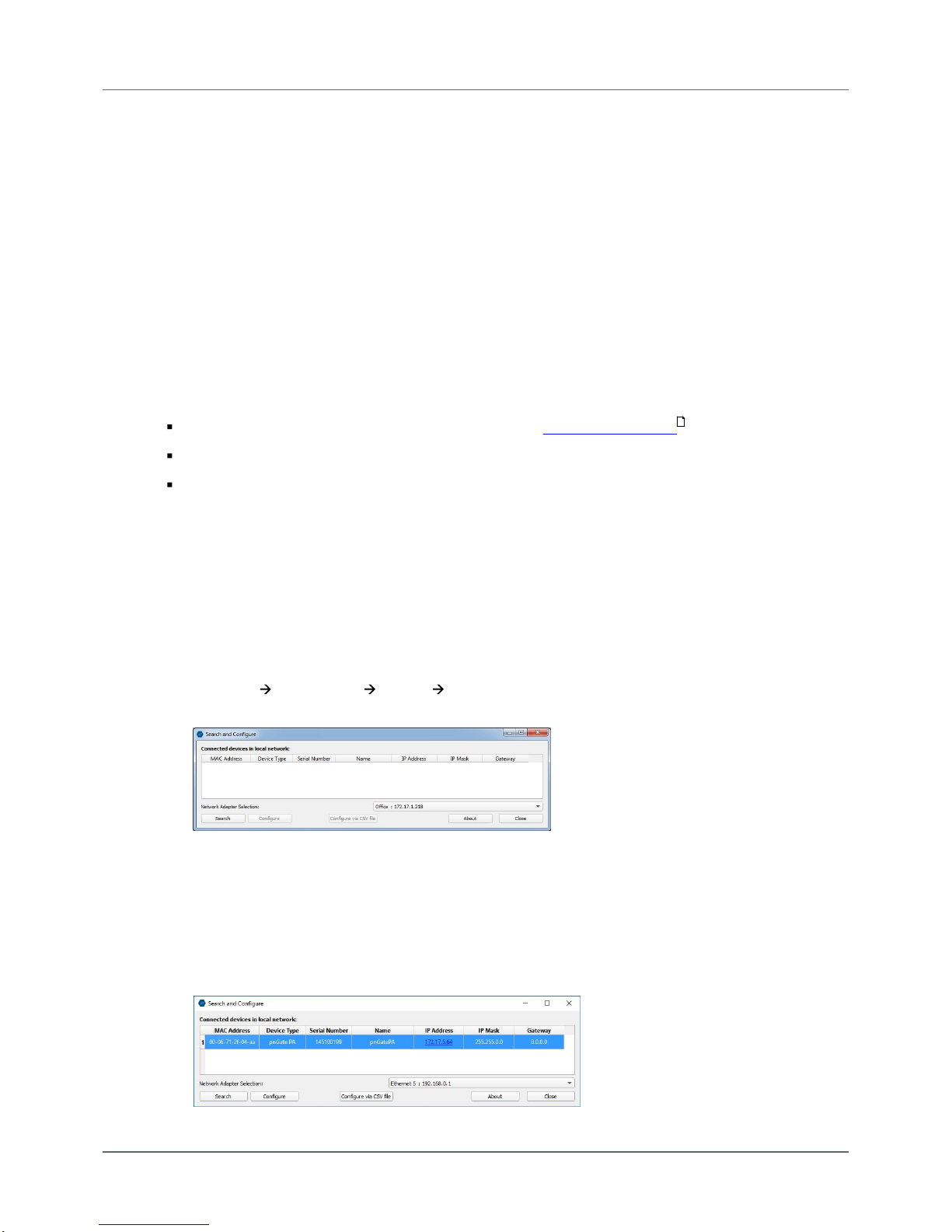
Searching for devices
The following steps apply to Windows 7.
1. Click Start All Programs Softing Search and Configure.
The application window is opened.
2. Open the Network Adapter Selection.
3. Select the network on which you want to search for the connected gateway.
This selection menu shows all networks you can access from your PC.
4. Click [Search] to start searching for connected devices.
The search may take some time. The window Connected devices in local network appears.
14
Chapter 4 - Configuration
Version EN-072018-1.22 17
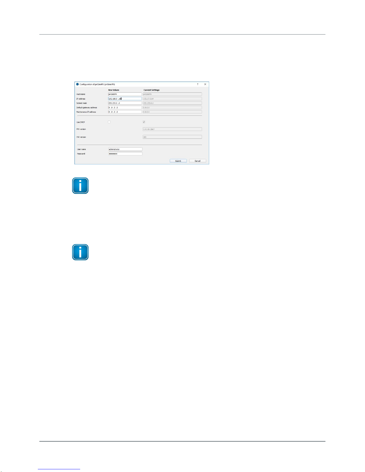
5. Select the network device you want to configure.
6. Click [Configure] or double-click the device.
The configuration window opens. Here you can modify all relevant values.
Note
If you are starting the connected pnGate PA / pnGate PB for the first time and you have
not yet assigned user roles for the gateway, the user name in the configuration window is
preset to administrator.
7. Enter the default password FGadmin!1 for username administrator.
8. Click [Submit].
The changed settings are written to the device.
Note
For the PROFINET communication to work properly ensure that the device's web server
does not use the same IP address that is used by the PROFINET engineering system (e.g. TIA
Portal) for the gateway.

pnGate PA / pnGate PB - User Guide
18 Version EN-072018-1.22
4.3 Setting the IP address of the PC
If you have not changed the IP address of the pnGate PA / pnGate PB as described in the previous Section
you will need to configure the IP address of your PC to access the gateway over the network from your
PC.
The following chapter describes how to set a static IP address in Windows 7. The steps below may vary
slightly for Windows 10.
1. Click Start Control Panel from Menu (Windows logo).
2. Select Network and Sharing Center (if the control panel opens in the icon view or select Network and
Internet Network and Sharing Center if you the control panel opens in the category view).
3. Click Local Area Connection under View your active networks. A new window opens.
4. Click [Properties]. A new window opens.
5. Select Internet Protocol Version 4 (TCP/IPv4) and click [Properties].
The following window opens..
6. Select Use the following IP address and enter a specific IP address and Subnet mask that corresponds
to your network environment. In our example we use the following settings:
IP-Adresse: 192.168.0.1
Subnet mask: 255.255.255.0
7. Depending on your network environment, you may need to enter your default gateway.
8. Click [OK] to confirm.
16

Chapter 4 - Configuration
Version EN-072018-1.22 19
4.4 User roles and permissions
Access to the pnGate PA / pnGate PB configuration tool is managed by user roles where each role has
certain permissions. The following user roles, permissions and passwords are available:
Role
Username
Password
Administrator
administrator
FGadmin!1
Maintenance
config
FGconfig!1
Operator
view
FGview!1
Expert*
expert
FS-QsHnc7BWa{6w<
Diagnostics*
diagnosis
?<fJ#\/$eB2qtGd*
*Backdoor accounts for Softing Support access. Currently supporting same features as administrator account.
The tables shows which permissions/actions can be executed by which user role:
Action
Admin / Diagn. / Exp.
Maintenance
Operator
Setting password
Configuring gateway
Reading configuration
Reading diagnostics

pnGate PA / pnGate PB - User Guide
20 Version EN-072018-1.22
4.5 Login to user interface
1. Open your web browser.
2. Type the IP address you set for your gateway or PC above into the address bar (URL field).
The web server login windows is opened.
Note
Depending on the web browser you are using the information presentation may vary.
3. Enter administrator in the User Name field and FGadmin!1 in the Password field.
4. Click [Login].
The user interface of the web sever opens with the information page showing details about the
gateway like the serial number, firmware version and Host ID.
Other manuals for pnGate PA
2
This manual suits for next models
1
Table of contents
Other Softing Recording Equipment manuals


