SOGEDIS 371E User manual

371E PUSH BUTTON DISPLAY
NOVEMBER 2017
1
Display and Control Panel
1. It enables the setting value of fridge to be modified and super cool mode to be activated
if desired. Freezer may be set to -16,-18,-20,-22,-24 °C, SF.
2. It is the Super Freeze mode symbol.
3. It is the alarm symbol.
4. It is the freezer set value screen.
Super Freezing Mode :
• To freeze plenty of food
How to use;
• Press set button until ‘SUPER’ led blink.
During this mode:
• Super freeze mode can be cancelled by the same
operation of selecting.
Demo mode :
This mode will be use for only sales points by salesman to show functions & modes to
customer without operating components as a compressor, fan, motor..Etc
Entering Demo mode:
•Firstly the power is on , with in 1 minute set the temperature to ‘’SUPER’’ and user will push
‘’SET’’ button for 10 seconds , Then appliance will go on “demo function” and Super LED
symbol will blink during the mode.
•All functions can be adjusted to show how they are adjusted to the customer.
Canceling Demo mode:
•For cancelling; Same operation will be used. If user will push SET button for 10 seconds,
demo function will be cancelled.
•When appliance is Demo mode; if plug is removed or there is an electricty breakdown;
demo mode will continue with current settings after user plug into or electricity breakdown
finish.
371E PUSH BUTTON DISPLAY
NOVEMBER 2017
2
Display and Control Panel
Temperature adjustment and activating SUPER COOLING Mode
Initial temperature value for Freezer Setting Indicator is -18 °C.
• Press set button once.
• When you first push this button, the last value
appears on the setting indicator of the freezer.
• Whenever you press on this button, lower
temperature will be set. (-16°C, -18C, -20°C,
-22°C, -24°C,)
• If you continue to press, it will restart from -16°C.
• The temperature value selected before Super
Freeze Mode is activated will
remain the same when the mode is over or
cancelled. The appliance continues to operate
with this temperature value.
Recommended Temperature Values for Fridge
When would it be adjusted? Inner Temperature
For Minimum Freezing Capacity -16˚C
In Normal Usage -18˚C, -20˚C,-22˚C
For Maximum Freezeing Capacity -24˚C, SF
371E PUSH BUTTON DISPLAY
NOVEMBER 2017
3
Fault Codes
Sensor short open circuit defect on display
Component defect on display
DEFECT TYPE
DETAILS
USER MODE
REACTION
SERVICE MODE
REACTION
Compressor
Defect
D sensor
temp >-10°C
(D sensor
temp.
unchanges
for10 min.
continuous
compressor
run
)
Display
ALARM Symbol
blinks
-
20 Set Symbol blinks
SENSOR
TEMPERATURE
USER MODE
REACTION
SERVICE MODE
REACTION
(1)
Freezer
>+50
°C or <-50°C
(sensor is
short or open)
Display
ALARM
Symbol
blinks
-
16 Set Symbol blinks
(2) Refrigerator
NA
NA
(3)
Defrost
Short
(< 100W) or <-50°C
-
18 Set Symbol blinks
(4) AT sensor
NA
NA
Breakdown of (1) and (2)
NA
Breakdown of (1) and (3)
-
16,-18 Set Symbol
blinks
Breakdown of (1) and (4)
NA
Breakdown of (2) and (3)
NA
Breakdown of (2) and (4)
NA
Breakdown of (3) and (4)
NA
Breakdown of (2) and (3) and (4)
NA
Breakdown of (1) and (3) and (4)
NA
Breakdown of (1) and (2) and (4)
NA
Breakdown of (1) and (2) and (3)
NA
Breakdown of all sensors
NA
Compressor Defect Error on display
***NOTE:To prevent the wrong alarms, this alarm status is disabled on following conditions:
•During the first 6 hours after the product was firstly connected.
•During the defrost period
•During the 30 minutes after a defrost
•During the first 2 hours that if door was open.

371E PUSH BUTTON DISPLAY
NOVEMBER 2017
4
Service Mode
Entering service mode:
Push SET button continuously for 10 seconds when -24 set symbol active. Appliance will enter service
mode 10 sec. later.
Canceling service mode:
Push SET button continuously for 10 seconds when -24 set symbol active. Appliance will enter service
mode 10 sec. later.
If service man do not push any buttons for 30 minutes when appliance is in service mode.
Service mode will be canceled automatically.
Service mode will be used only by professionals.
1.Push Starting program
Push set button 5 second at service mode.
Freezer set value screen light as components are checked.
“-16 set symbol” will light when compressor is ON
“-18 set symbol” will light heater will be ON
“-20 set symbol” will light fan will be ON
2.Push Forced Defrost and Forced Canceling of Defrost
-18 set symbol will light during this mode.. Mode can be canceled manually or automatically.
Manual canceling will be done by pushing SET button. Symbol will be OFF if defrost is canceled
manually. Appliance will return to initial Service mode reaction.
If manual canceling of this function is not performed in 40 min.
Service mode will be canceled. Appliance will check if defrost is finished in this 40min. It YES,
appliance will go on from previous set values. But if defrost is not finished , appliance will go on
defrost till it finishes and then go on from previous set values.

371E PUSH BUTTON DISPLAY
NOVEMBER 2017
5
REVERSING THE DOOR
3. Displace the door (Picture-3)
Picture-1
1. Hold the top hinge cover and remove it toward
that direction (Picture-1)
2.Unscrew the screws fixing the top hinge
and remove it. (Picture-2)
Picture-2
Picture-3

371E PUSH BUTTON DISPLAY
NOVEMBER 2017
6
REVERSING THE DOOR
4. Unscrew the adjustable foot (Picture-4)
Picture-4
5. Unscrew the bottom hinge screws. (Picture-5)
Picture-5
Picture-6 Picture-7
7. Screw the bottom hinge to the left bottom
side of refrigerator. Screw the adjustable
foot there. (Picture-7)
6. Unscrew the bottom hinge pin and
screw it to other hole. (Picture-6)
8. Unscrew the two screws fixing stopper
and stopper support plate under the
door. After that screw the other side.
(Picture-8)
Picture-8

371E PUSH BUTTON DISPLAY
NOVEMBER 2017
7
REVERSING THE DOOR
9. Remove the hinge cover on the top panel and replace
to other side.(Picture-9)
Picture-9
Picture-10
10. Place the door to the bottom hinge and
screw the top hinge to the top panel.
(Picture-10)
Picture-11
11. Place the top hinge cover. (Picture-11)

371E PUSH BUTTON DISPLAY
NOVEMBER 2017
ASSEMBLE & DISASSEMBLE OF AIR DUCT
1. Remove the refrigerator glass shelves
and the flap cover supports left and right.
(Picture-1 / Picture-2)
Picture-1
Picture-6
Picture-2
Picture-3
2. Remove the plugs by pulling them under the base with a pointed device to remove the screw
plugs and remove the screws. (Picture-3-4-5)
3. Keep the air duct by the left side or rigth side and stretch it.
Get rid of the nails. (Picture-6)
Picture-4 Picture-5
Warning: Make sure the unit is unplugged.

371E PUSH BUTTON DISPLAY
NOVEMBER 2017
9
1. Remove the fan motor connector, unscrew the fan motor fixing screws and displace the fan motor
and remove the propeller. (Picture-1 / Picture-2)
Picture-1 Picture-2
2. Displace the details on the fan motor
box. (Picture-3)
FAN
MOTOR
FAN MOTOR
COVER
PROPELLER
FAN
MOTOR
BOX
SCREWS
FAN
MOTOR
RUBBER
Fan Motor ComponentsPicture-4
ASSEMBLE & DISASSEMBLE OF FAN MOTOR

371E PUSH BUTTON DISPLAY
NOVEMBER 2017
ASSEMBLE & DISASSEMBLE OF FIN EVAP
1. Take out the fin evap heater (blue) connector and remove the bitumen covering the tubes.
(Picture-1 / Picture-2)
Picture-1
Warning: This process needs gas deflation, gas re-charging and welding
processes so its need to be done by trained professionals.
Warning: Before cutting the tube follow make sure the gas is evacuated.
2. To take out the evaporator, tubes need to be cut with oxygen welding. (Picture-3 / Picture-4)
Remove the evaporator by pulling forward in a horizontal direction. Do not push it up or down.
You may broke the fixing plastics.
Picture-3
Picture-2
Picture-4

371E PUSH BUTTON DISPLAY
NOVEMBER 2017
Replacement Head Panel Display
ASSEMBLE & DISASSEMBLE DISPLAY
1. By aid of a flat screwdriver or smilar tools remove taps and then unscrew
4. Unscrew screws on the card and unhook snapfits and then replace card with new one
5. After disassembly head panel , mainboard in the housing can be reached. Lift up
mainboard and pull outward from housing then disconnect sockets on the board,
6. For reassembly , follow steps vice versa
2. Unhook snapfits on the head panel by reaching from related cavities and pull head panel
backward
3. To disconnect head panel unplug socket from the display card

371E PUSH BUTTON DISPLAY
NOVEMBER 2017
1111
Replacement Head Panel and Main Board
1. First remove cover by pulling leftward as
shown below.
ASSEMBLE & DISASSEMBLE OF DISPLAY
2. Remove other cover by pulling backward
from top side of the cover as shown below
1
3
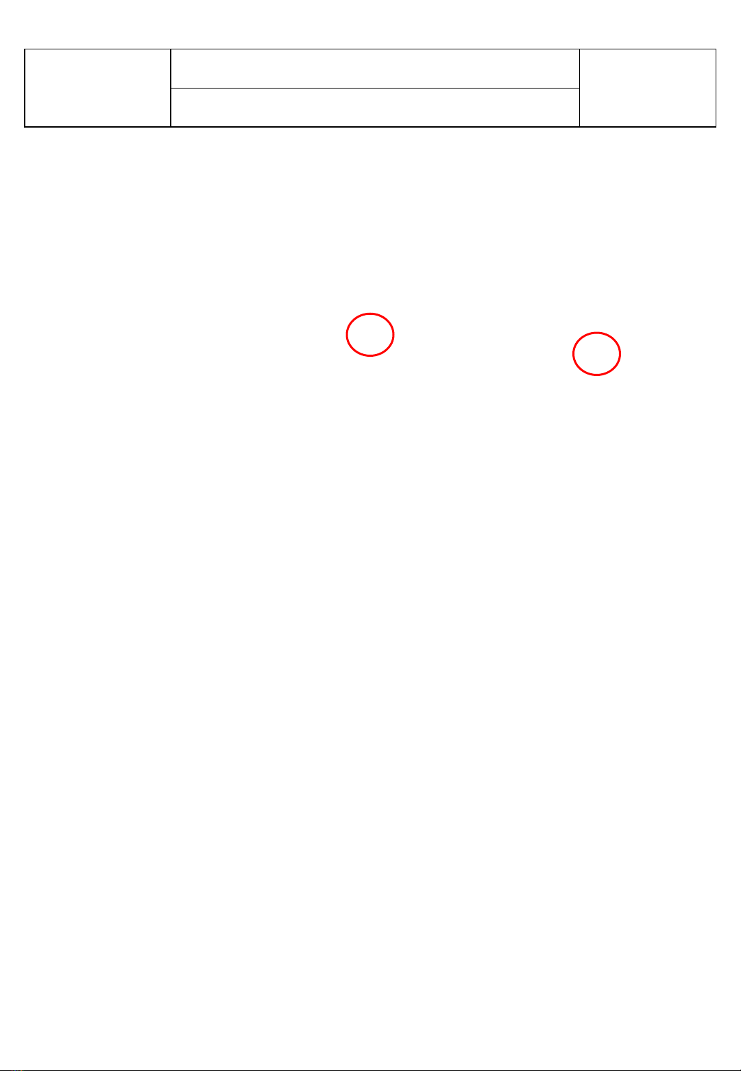
3. Unscrew screws marked with red circle at the picture below.

371E PUSH BUTTON DISPLAY
NOVEMBER 2017
12
4. Disassemble snapfits at the area marked with red circle at the picture below .
It can be used any suitable tool to disassemble.
ASSEMBLE & DISASSEMBLE OF DISPLAY
5. Unplug socket on the board assembled head panel.
371E PUSH BUTTON DISPLAY
NOVEMBER 2017
13
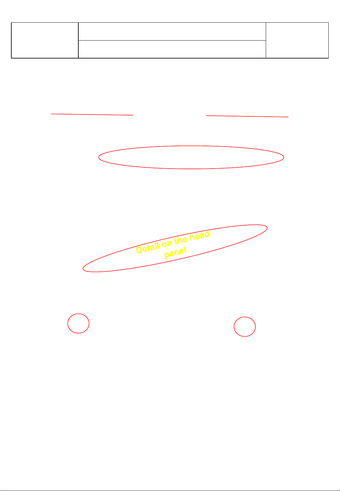
6. To reassemble head panel ; first plug socket mentioned before and then place detail on
the head panel to related detail on the cover and then push head panel to place snapfits
marked with red circle below.
Detail on the cover
Snap-fit
ASSEMBLE & DISASSEMBLE

371E PUSH BUTTON DISPLAY
NOVEMBER 2017
14
7. Then screw head panel with screwdriver and assemble covers and complete head
panel assembly.
ASSEMBLE & DISASSEMBLE OF DISPLAY
8. Pull cover backward and remove from housing

371E PUSH BUTTON DISPLAY
NOVEMBER 2017
15
ASSEMBLE & DISASSEMBLE OF DISPLAY
9. Then unplug all sockets.
10. To reassemble cover first plug all sockets related place on the board.
371E PUSH BUTTON DISPLAY
NOVEMBER 2017
16
11. To reassemble cover pay attention to assemble with right direction. Details on the cover
and housing should be matched eachother
Housing
Cover
ASSEMBLE & DISASSEMBLE OF DISPLAY

371E PUSH BUTTON DISPLAY
NOVEMBER 2017
17
ASSEMBLE & DISASSEMBLE SENSOR
Picture-1 Picture-2
Remove the freezer sensor cover by pulling forward and disconnect sensor connector.
(Picture-1 / Picture-2)
Warning: Pay attention not to damage to the sensor cover details!
ASSEMBLE & DISASSEMBLE LED
Remove the led cover by pulling forward and unscrew the two screws fixing the led and remove it.

Page 1 sur 6
INFORMATION TECHNIQUE
CHASSIS
371E
Activation du Mode Service
Entrer dans le mode service:
L'appareil entrera en mode service, en appuyant sur le bouton de réglage (repère 1) en continu
pendant 10 secondes quand le voyant -24°C est allumé.
Annuler le Mode Service :
Procéder de la même façon que précédemment pour annuler le mode service.
Si vous appuyez sur aucunes touches pendant 30 minutes, l’appareil annule automatiquement
le mode service.
Le mode service est utilisé uniquement par des techniciens professionnels.
1

Mode Service
Appuyez 5 secondes sur la touche « réglage » en mode service (repère 1 )
Chaque valeur de consigne de température -16°C à -24°C s’allume pour contrôler les
composants de l’appareil
Numéro -16 : s’allume : test du compresseur
Numéro -18 s’allume : l’élément chauffant pour le dégivrage fonctionne
Numéro -20 s’allume : le ventilateur est actif
Appuyez 2 fois sur la touche « réglage »
Le symbole -18°C s'allume pendant le mode. Le mode peut être annulé manuellement ou
automatiquement.
L'annulation manuelle se fera en appuyant sur le bouton « Réglage ». Le symbole sera désactivé
si le dégivrage est annulé manuellement. L'appareil retournera au mode service initiale.
Si l'annulation manuelle de cette fonction n'est pas effectuée dans 40 min.
Le mode de service sera annulé.
L'appareil vérifiera si le dégivrage est terminé dans ces 40 minutes. Si oui, l'appareil continuera
à partir des valeurs de réglage précédentes. Mais si le dégivrage n'est pas terminé, l'appareil
continuera à dégivrer jusqu'à ce qu'il se termine, puis continuera à partir des valeurs de
consigne précédentes.
CHASSIS
371E
Page 2 sur 6
Table of contents
Other SOGEDIS Freezer manuals

Popular Freezer manuals by other brands


CombiSteel
CombiSteel 7072 Series user manual

CHILLY MOOSE
CHILLY MOOSE CF 45 user manual

True Manufacturing Company
True Manufacturing Company 922341 installation manual

LG
LG GC-M257CQFL owner's manual
 Specification sheet")
Electrolux
Electrolux Air-O-Chill 726990 (AOFP101CU4) Specification sheet

Hisense
Hisense RS741N4AC2 User's operation manual