manuals.online logo
Brands
  1. Home
  2. •
  3. Brands
  4. •
  5. CyberPower
  6. •
  7. UPS
  8. •
  9. CyberPower CyberShield DTC36U12V User manual

CyberPower CyberShield DTC36U12V User manual

Other CyberPower UPS manuals

CyberPower BRICs Series User manual

CyberPower

CyberPower BRICs Series User manual

CyberPower PR750RT2U User manual

CyberPower

CyberPower PR750RT2U User manual

CyberPower OL6KRT User manual

CyberPower

CyberPower OL6KRT User manual

CyberPower AVR Series User manual

CyberPower

CyberPower AVR Series User manual

CyberPower SE450G User manual

CyberPower

CyberPower SE450G User manual

CyberPower BU600E User manual

CyberPower

CyberPower BU600E User manual

CyberPower 649532210039 User manual

CyberPower

CyberPower 649532210039 User manual

CyberPower PFC SINEWAVE UPS Series User manual

CyberPower

CyberPower PFC SINEWAVE UPS Series User manual

CyberPower 649532010066 User manual

CyberPower

CyberPower 649532010066 User manual

CyberPower PR750LCDN User manual

CyberPower

CyberPower PR750LCDN User manual

CyberPower UT550G User manual

CyberPower

CyberPower UT550G User manual

CyberPower 649532015795 User manual

CyberPower

CyberPower 649532015795 User manual

CyberPower UP825 User manual

CyberPower

CyberPower UP825 User manual

CyberPower PR3000ELCDRT2U User manual

CyberPower

CyberPower PR3000ELCDRT2U User manual

CyberPower PR3000 User manual

CyberPower

CyberPower PR3000 User manual

CyberPower CPS1000EI User manual

CyberPower

CyberPower CPS1000EI User manual

CyberPower BL1450U User manual

CyberPower

CyberPower BL1450U User manual

CyberPower BU600ELCD User manual

CyberPower

CyberPower BU600ELCD User manual

CyberPower CSN27U12V Installation guide

CyberPower

CyberPower CSN27U12V Installation guide

CyberPower UPS BR850ELCD User manual

CyberPower

CyberPower UPS BR850ELCD User manual

CyberPower CP350SLG User manual

CyberPower

CyberPower CP350SLG User manual

CyberPower OR500LCDRM1U User manual

CyberPower

CyberPower OR500LCDRM1U User manual

CyberPower ST425 User manual

CyberPower

CyberPower ST425 User manual

CyberPower Paragon OL1000RMXL2U User manual

CyberPower

CyberPower Paragon OL1000RMXL2U User manual

Popular UPS manuals by other brands

AEG Protect 3.M 2.0 manual

AEG

AEG Protect 3.M 2.0 manual

Alpha Novus FXM 650 Installation and operation manual

Alpha

Alpha Novus FXM 650 Installation and operation manual

Pylontech Victron & Pylontech US5000 manual

Pylontech

Pylontech Victron & Pylontech US5000 manual

BEL LDX-U20 user manual

BEL

BEL LDX-U20 user manual

Mustek PowerMust 530(B) Plus Startup manual

Mustek

Mustek PowerMust 530(B) Plus Startup manual

Emerson Liebert NXL series Operation and maintenance manual

Emerson

Emerson Liebert NXL series Operation and maintenance manual

MAKELSAN BOXER SERIES user manual

MAKELSAN

MAKELSAN BOXER SERIES user manual

Block PC-0524-400-0 manual

Block

Block PC-0524-400-0 manual

Eaton 3S Advanced user's guide

Eaton

Eaton 3S Advanced user's guide

Best Power 610 quick start guide

Best Power

Best Power 610 quick start guide

Best Power Unity/I UT3K user manual

Best Power

Best Power Unity/I UT3K user manual

Mustek PowerMust 400 Offline user manual

Mustek

Mustek PowerMust 400 Offline user manual

Xantrex Trace 512 UR-UPS owner's manual

Xantrex

Xantrex Trace 512 UR-UPS owner's manual

Forza SL-1501UL user manual

Forza

Forza SL-1501UL user manual

LEGRAND keor 310081 quick start guide

LEGRAND

LEGRAND keor 310081 quick start guide

Eaton Powerware 9125 installation guide

Eaton

Eaton Powerware 9125 installation guide

ABB Conceptpower DPA 500 operating manual

ABB

ABB Conceptpower DPA 500 operating manual

ZincFive BC Series installation instructions

ZincFive

ZincFive BC Series installation instructions

manuals.online logo
manuals.online logoBrands
  • About & Mission
  • Contact us
  • Privacy Policy
  • Terms and Conditions

Copyright 2025 Manuals.Online. All Rights Reserved.

User’s Manual for
CyberShield
DTC36U12V
CyberShield UPSs are designed to provide a local power solution for
cable telephony, wireless local loop (WLL), and fiber to the home
(FTTH) broadband equipment.
IMPORTANT SAFETY WARNINGS
(SAVE THESE INSTRUCTIONS)
INSTA LLATION
OVERVIEW
DESKTOP USE:
1.) Open the battery door at the back of the DTC36U12V and connect the battery wires.
2.) Plug AC power cable into wall outlet.
3.) Connect the communication cable and simply place the DTC36U12V unit on or
underneath desk to begin backing up the optical home network.
BATTERY REPLACEMENT
This battery is hot-swappable. As long as utility power is on, you may leave the UPS and connected
equipment on while replacing a new battery.
OPERATION
Connect equipment and power:
Step1. Plug the UPS power cord into the utility power cord inlet.
Step2. Plug the UPS power cord into the wall outlet.
COLD START
Step 1:
Connect the AC cable to the wall outlet.
Step 2:
Connect the communication cable between the DTC36U12V
and the ONT device.
Step 1:
a. Slide off the battery
cover at the back of the
DTC36U12V unit.
Step 2:
a. Remove the battery from
the enclosure.
b. Disconnect both battery
cable connectors.
Step 3:
a. Install the new battery by connecting
the red lead to the positive terminal
and the black lead to the negative
terminal.
b. Slide the battery back into the
compartment.
c. Replace battery cover to resume
normal operation.
Step 3:
Install the cable retainer to secure the
commnication cable.
Step 4:
Use the enclosed wall mount template to locate screws on the
wall. Hang the DTC36U12V on the screws which are located on
the wall.
The cold start feature is to supply power to the UPS and connected equipment when the UPS
shuts down and no utility power is available. Before using the cold start feature, please make sure
that the battery is properly charged. To turn on the cold start feature, please press and hold the
cold start button until 4 LED indicators light up.
This manual contains important instructions regarding the installation and operation of this device.
Read this manual thoroughly before attempting to unpack, install or operate this device.
CAUTION! The battery can energize hazardous live parts inside even when the AC input power is
disconnected.
CAUTION! To prevent the risk of fire or electric shock, install in a temperature and humidity
controlled indoor area, free of conductive contaminants. (Please see specifications for
acceptable temperature and humidity range.)
CAUTION! To reduce the risk of electric shock, do not remove the cover, except to service the
battery. No user serviceable parts inside, except for the battery.
CAUTION! When replacing batteries, the replacement should have the same rating as follows,
Listed/Certified Valve Regulated Lead Acid Battery, 12V, max. 9Ah.
CAUTION! Risk of Energy Hazard, 12V, max.9 Ampere-hour battery. Before replacing batteries,
remove conductive jewelry such as chains, wrist watches, and rings and use tools
with insulated handles. High energy through conductive materials could cause
severe burns.
CAUTION! Do not dispose of batteries in a fire. The battery may explode if improperly disposed.
Recycle batteries in accordance with local regulations.
CAUTION! Do not open or mutilate batteries. Released material is harmful to the skin and eyes. It
may be toxic.
The UPS battery charges when it is connected to utility power. The battery
charges fully during the first 24 hours of normal operation. Do not expect full
battery run capability during this initial charge period.
Once the battery is disconnected, the connected equipment is not protected
from power outages.
Deliver spent batteries to a recycling facility or ship to the manufacturer in the
replacement battery packing material.
7
6
5
4
Description
LED Indicator
Alarm Silence Button
Cold Start Button
Cable Retainer Installation Point
Communication Cable Connector
AC Power Cable Connector
Battery Cover
Number
1
2
3
4
5
6
7
ALARM SILENCE
The audible alarm will be enabled when the unit is operating from battery or battery power is low.
Press the Alarm Silence button for 0.5 seconds, the unit will beep once confirming that audible
alarms have been temporary disabled for 24 hours. Press this button one more time for 0.5 seconds
to enable audible alarms again. The unit will beep twice confirming that audible alarms have been
enable. Or press and hold the Alarm Silence button for 15 seconds the units will beep once confirm-
ing that audible alarms have been disabled permanently. To restore the audible alarm, press and
hold the Alarm Silence button for 15 seconds and the unit will beep twice confirming that audible
alarms have been enabled.
WALL MOUNT USE:
1
2
3
COMMUNICATION SIGNALS
For more information, please contact:
CyberPower Systems ( USA ), Inc. 4241 12th Avenue East, Suite 400, Shakopee, MN55379 Phone: (952)403-9500 Fax: (952)403-0009 www.cpsww.com
CyberPower Systems ( EUROPE ), Inc. www.cpsww.eu
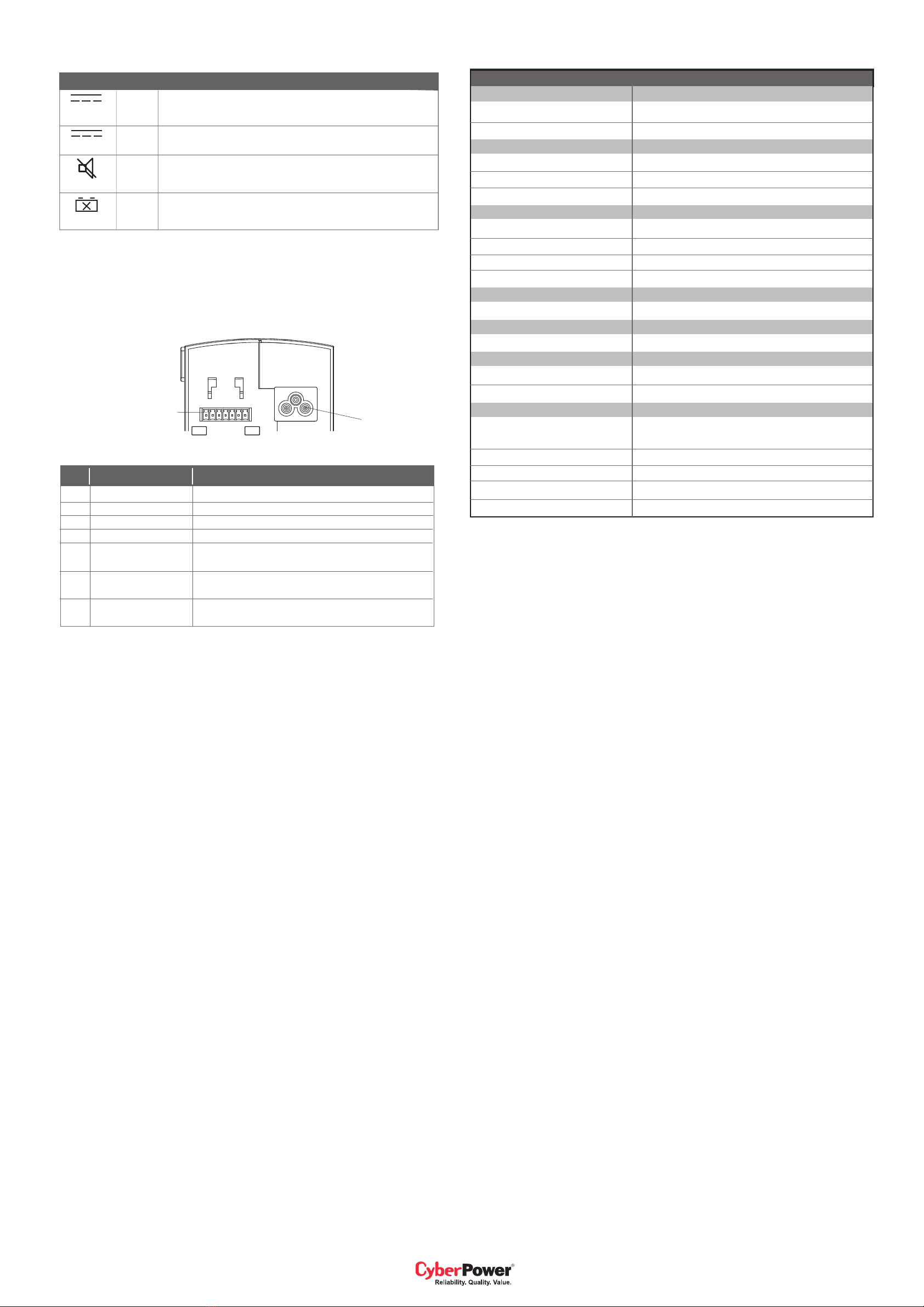
12V
12V RTN
SIG RTN
ON BATTERY
REPLACE
BATTERY
BATTERY
MISSING
LOW BATTERY
+ Voltage output
- Voltage output
Signal return
Low when operating from utility line.
Low when battery is charged.
Open when battery fails the self test.
Low when battery is present.
Open when battery is missing.
Low when battery is near full charge capacity.
Open when operating from a battery with < 45% capacity.
SignalPin Message
LIMITED WARRANTY
CyberPower warrants to you, the Initial Purchaser, that the Product will be free from defects in material and workmanship for three years from the date of original purchase, subject to the terms of this Limited
Warranty. This Limited Warranty gives you specific rights, and you may have other rights, which vary from State to State or Province to Province.
Any Implied Warranty of Merchantability or for Fitness for a Particular Purpose, if applicable to the Product, is limited in duration to three years. This provision shall NOT create any Implied Warranty or
Merchantability or of Fitness for a Particular Purpose that would not otherwise apply to the Product. NOTE: Some States and Provinces do not allow limitations on how long an implied warranty lasts,
so the above limitation may not apply to you.
To be covered you must still be the owner of the Product at the time of the failure that results in the claim made under this Limited Warranty. Your sole and exclusive remedies are those provided by this
Limited Warranty. This exclusion of other express warranties applies to written and oral express warranties. CyberPower excludes any liability for personal injury. CyberPower excludes any liability for direct,
indirect, special, incidental, or consequential damages, whether for damage to or loss of property, loss of profits, business interruption, information or data. This exclusion applies even though damage or loss
is caused by negligence or other fault. NOTE: Some States or Provinces do not allow the exclusion or limitation of incidental or consequential damages, so the above limitation may not apply to you.
DO NOT USE FOR MEDICAL OR LIFE SUPPORT EQUIPMENT OR OTHER HIGH RISK ACTIVITIES.
CyberPower does not sell the PRODUCT for use in high-risk activities. The PRODUCT is not designed or intended for use in hazardous environments requiring fail-safe performance, including the operation
of nuclear facilities, aircraft navigation or communication systems, air traffic control, weapons systems, life support or medical applications or for use in any circumstance in which the failure of the PRODUCT
could lead directly to death, personal injury, or severe physical or property damage, or that would affect operation or safety of any medical or life support device (collectively, "High Risk Activities").
CyberPower expressly disclaims any express or implied warranty of fitness for High Risk Activities. CyberPower does not authorize use of any PRODUCT in any High Risk activities.
ANY SUCH USE IS IMPROPER AND IS A MISUSE OF A CYBERPOWER PRODUCT.
The Limited Warranty is governed by the laws of the United States and the State of Minnesota, without reference to conflict of law principles. The application of the United Nations Convention of Contracts for
the International Sale of Goods is expressly excluded.
FCC NOTICE:
This equipment has been tested and found to comply with the limits for a Class B digital device, pursuant to part 15 of the FCC Rules. These limits are designed to provide reasonable protection against
harmful interference in a residential installation. This equipment generates, uses and can radiate radio frequency energy and, if not installed and used in accordance with these instructions, may cause harmful
interference to radio communications. However, there is no guarantee that interference will not occur in a particular installation. If this equipment does cause harmful interference to radio or television reception,
which can be determined by turning the equipment off and on, the user is encouraged to try to correct the interference by one or more of the following measures: (1)Reorient or relocate the receiving antenna.
(2) Increase the separation between the equipment and receiver. (3) Connect the equipment into an outlet on a circuit different from that to which the receiver is connected. (4) Consult the dealer or an
experienced radio/TV technician for help.
CAUTION: Shielded signal cables must be used with this device to ensure compliance with Class B FCC limits.
CAUTION: Any changes or modifications not expressly approved by Cyber Power could void the authority granted by the FCC to operate this equipment.
1
2
3
4
5
6
7
AC Inlet
Communication signals
The communication signals of this unit are isolated from the internal circuitry via open
collector opto-coupled transistors. The connection “SIG RTN” (Signal Return) is a common
return point for all communication signals. In the typical application, the attached equipment
digital ground connects to Signal Return, and pull-up resistors turn the open collector
signals into logic levels.
DTC36U12V
K01-3612009-01
LED INDICATOR
Indicator Color Condition
DC
BATTERY
SYSTEM
STATUS
MUTE
Green
Green
Orange
Red
Indicates normal mode of operation.
Indicates the battery is supplying the power. At 45% battery capacity,
the LED will flash and then alarm will beep 4 times per minute.
Press and hold the button “Alarm Silence” for 0.5 second to silence
the audible alarm for 24 hours, and the LED will flash.
Battery replacement required. Alarm will beep once every 15 minutes.
The LED also illuminates when battery is absent.
SPECIFICATION
Model
DTC36U12V
Input
Voltage Range
100Vac - 240Vac
Frequency Range
50-60Hz
Output
On Battery Output Voltage
12Vdc
Continuous Power Capability
36W
Efficiency (at 75% Max Load)
≥80%
Battery
Battery Type
Sealed, Maintenance Free Lead-Acid Battery
Numbers of Battery
12Vdc / 7.2AH x 1
Typical Recharge Time
14 Hours (90% charged)
Yes
Replaceble
Surge Protection and Filtering
Lightning / Surge Protection
Yes
Management
Battery Auto-Charge
Yes
Physical
Dimensions (LxWxD)
16.8cm x 8.1cm x 18.5cm
Weight (Net)
3.13kg (with 7.2AH battery)
Environment
Operating Temperature
-4ºF - 113ºF (-20ºC - 45ºC)
Operation at 50ºC (122ºF) with de-rating to 30W
Operating Humidity
0 – 95% noncondensing within enclosure
Max Operating Elevation
10,000ft (3,000m)
Max Storage Elevation
50,000ft (15,000m)
Storage Temperature
Pin 1 Pin 7
-4ºF - 113ºF (-20ºC - 45ºC)