solaceair FM2-12 Installation and operating instructions
TROUBLESHOOTING
• The LED should light when the furnace blower is running.
• Both lamps use the same multivoltage ballast.
If the LED does not light: 1. Check to be sure there is power to the unit.
2. Be sure lamp connectors are fastened securely.
3. If the LED still does not light, replace lamp(s).
4. If still not operating, replace ballast.
Note: Standard off-the-shelf lamps are not compatible with this unit. Use of improper lamps will void warranty.
WARRANTY
All electronic components carry a lifetime warranty to the original homeowner. In addition there is a four-year
warranty from the date of installation for any subsequent owner. The manufacturer reserves the right to send
replacement parts or to replace the unit at its discretion. This warranty does not cover any labor or damage
resulting from improper installation or abuse. Use of any lamp other than the manufacturer’s lamp designed for
this device will void the warranty.
The original lamps are warranted for a period of two years. This warranty does not cover lamps broken during
shipping, installation or as a result of improper handling.
All returns are routed through your contractor/wholesaler and must be approved and accompanied by an RGA#.
Please call 800-578-7873 and we will guide you through the return procedure.
This warranty gives you specic legal rights and you may also have other rights which vary from state to state.
MAINTENANCE
This maintenance schedule is only a guideline, determined by average conditions. Actual conditions will dictate
the frequency of cleaning and/or replacement of lamps. Do not touch the glass portion of the lamps with bare
hands because oils from the hands can cause “hot spots” which reduce lamp life. Handle either by the end caps or
use a soft cloth. If you accidentally touch a lamp, clean it using a soft cloth dampened with rubbing alcohol.
CLEANING THE LAMPS - Recommended interval: 12 months (Follow the procedure below)
Replacement lamps are available through your HVAC contractor.
REPLACING THE LAMPS - Recommended interval: 24 months. (Follow procedure below excluding #6.)
Note: Standard off-the-shelf lamps are not compatible with this unit. Use of improper lamps will void warranty.
1. Disconnect power to the unit.
2. Remove the cover from the unit by removing the four machine screws. Remove the oxidation control (Figure A).
3. Unplug the lamp from each lamp connector.
4. Remove lamp holders using a 1/4 size nut driver (Figure A).
5. Remove each lamp by grasping the end cap and extract carefully.
6. Using a soft cloth moistened with rubbing alcohol, wipe down each lamp. If there is a large build-up of dust
particles, you may wish to use a can of air rst. Always handle lamps by end caps.
7. Slide one lamp back into lamp opening. Reinstall lamp holder.
8. Repeat step 7 for second lamp.
9. Plug each lamp into the corresponding lamp connector.
10. Align the oxidizing control with adjustment linkage and replace cover. (Figure A).
Secure cover using the four machine screws.
11. Restore power to unit.
For Technical Support Call (800)578-7873 © 2018 Form GEN 823 (04/18)
The following parts are included: • FM2 Unit
• Germicidal Twin H Lamp (packed in lamp box)
• Four Sheet Metal Screws
• Installation & maintenance instructions
• Alcohol pad for cleaning lamps
• Strain relief connector
When installing and using this electrical equipment, basic safety precautions
should always be followed including the following:
1. READ AND FOLLOW ALL INSTRUCTIONS.
2. Minimum living space for this product is 1,200 square feet.
3. Always be sure the unit is unplugged during installation or service procedures.
4. The ultraviolet light produced by the UV lamp is harmful to your eyes. Do not look directly at
the lamp. Should it become necessary to view the lamp, use UV-protected sunglasses.
Lors de l’installation et de l’utilisation de cet équipement, des précautions devront être suivies.
1- Lire et suivre les étapes attentivement.
2- Espace minimum d’une habitation pour ce produit est de 1,200 pi. carrés
3- Assurez vous de toujours débrancher avant l installation ou le service.
4- Ne pas regarder la lampe directement avec les yeux. Si nécessaire de le faire,
veuillez porter les lunettes de soleil contre les rayons U.V.
IMPORTANT: SAFETY INSTRUCTIONS
Important: Instructions de securité
3099107
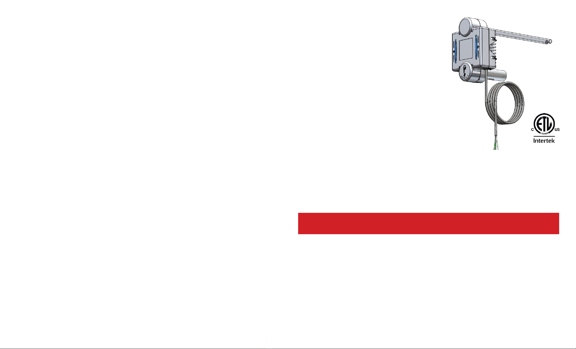
FM2-12, FM2-16
MultiVoltage Oxidizing UVC System
Installation & Maintenance Instructions
UNPACKING THE UNIT
Each unit is shipped with the 5” lamp installed and the germicidal
lamp placed in a box with protective packaging. Carefully
remove lamp from the tube taking care to not touch the glass
portion of the lamp with bare hands. Oils from the hands can
cause “hot spots” which reduce lamp life. Handle by the end
caps or use a soft cloth. If you accidentally touch a lamp, clean it
using the included alcohol cleaning pad or a soft cloth dampened
with rubbing alcohol. The lamp is fragile and proper care must be
taken when removing from packaging.

INSTALLATION: Living space, 1,200 square feet minimum.
Best results are achieved when the unit is installed where the HVAC system air temperature is most constant.
Therefore, the preferred installation is on the return side of the furnace. If return side installation is not possible,
install the unit on the supply side. Mount the FM2 upstream when installing in combination with a polarized media
air cleaner.
If there is a device that creates ozone in the space such as an ionizing air cleaner, it is recommended the FM2
not
be used in the application. For example, an FM1 could be substituted. Homes with multiple air handlers: install one
FM2 on the main level air handler and an FM1 on the other air handler(s).
Do not locate the unit within 20” of plastic materials that will be directly exposed to the UV light, such as wiring,
return side humidier or certain types of air lters. Check with the lter manufacturer to see if their material is UV
resistant. Over time, UV light may degrade some plastics and petroleum based materials.
Do not touch the glass portion of the lamps with bare hands because oils from the hands can cause “hot spots”
which reduce lamp life. Handle either by the end caps or use a soft cloth. If you accidentally touch a lamp, wipe it
off using the included alcohol cleaning pad or a soft cloth dampened with rubbing alcohol.
1. Cut out the shaded area of the installation template. (Please see insert.)
2. Center the template on the longitudinal axis of the plenum and attach with tape.
Trace the hole pattern for the unit and mark centers for mounting screws. (Airow direction is marked on the unit.)
3. Cut openings for the unit using a 2” hole saw or tin snips.
4. Remove the cover from the unit by removing the four machine screws.
5. Attach the unit to the air duct using the four self tapping sheet metal screws provided.
6. Remove the germicidal lamp holder using a 1/4 size nut driver (Figure A).
7. Slide the germicidal lamp into lamp opening.
8. Reinstall the lamp holder and plug lamp into connector.
10. Replace cover and secure using the four machine screws.
Figure A
Oxidation
Lamp holder
Germicidal
Lamp holder
Oxidation / odor control
WIRING
This unit must cycle with the furnace blower. Wire unit to an EAC terminal or current-sensing relay to cycle the
unit with the system fan. The multi-voltage ballast is self-adjusting and operates with voltages from 120 - 240 VAC.
For 120V wiring connect the black wire to L1, white wire to neutral, green wire to ground.
For 240V wiring install 5 amp in-line fuses then connect the black wire to L1, white wire to L2, green wire to
ground. Be sure power cord is secured with included strain relief connector. Wire the unit in accordance with local
wiring codes. After installing, verify voltage is operating between 120 - 240 VAC with air handler operating.
SETTING THE ACTIVATED OXYGEN OUTPUT LEVEL
• The air purication process occurs only while air is circulating through the HVAC system.
•
The oxidizing level can be easily adjusted as needed using the “Oxidation Odor Control” lever on the unit.
Start with the setting in the normal range. Decrease the setting if an activated oxygen odor is detectable.
If household odors are noticeable after 24 hours, increase the setting.
Oxidation / odor Control
For Technical Support Call (800)578-7873
FM2 Shown installed on a
furnace. For best results,mount
the unit on the air return.
AIR STREAM
LSK25403-16 / LSK25403-12 LSK-36-16-RF / LSK-24-12-RF
LAMP KITS FOR FM2
36 Watt UV/Oxi Lamp Service Kit with 12” UV Lamp LSK25403-12
44 Watt UV/Oxi Lamp Service Kit with 16” UV Lamp LSK25403-16
24-Watt 12” UV lamp with built in reector for directional irradiation LSK-24-12-RF
36-Watt 16” UV lamp with built in reector for directional irradiation LSK-36-16-RF

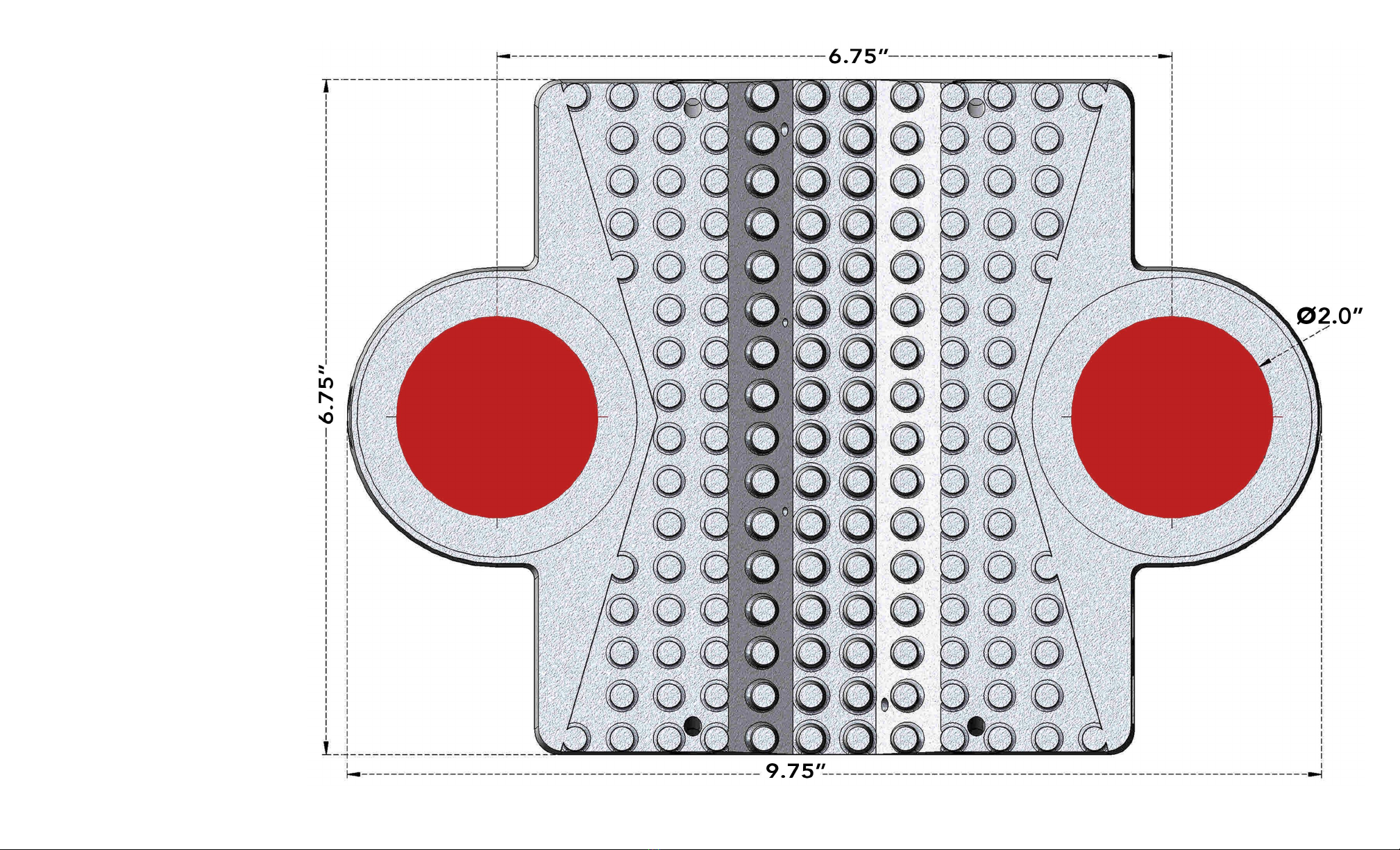
1. Cut out area of template indicated by the
two red shaded circles if using a hole saw.
2. Place template on the return path of the
HVAC system and trace the hole pattern for
the unit and mark centers for mounting
screws. Unit must be oriented so long
dimension is parallel to the direction of
the air ow. Please note the airow
direction marked on the unit.
3. Cut opening for the unit.
4. Install unit into air duct so that airow
matches direction indicated on side of unit
using the four self tapping sheet metal
screws provided.
This manual suits for next models
1
Popular Air Cleaner manuals by other brands


EcoQuest
EcoQuest Living Air Classic HEPA instruction manual

Plasma Air
Plasma Air AutoClean 1560 Installation, operation & maintenance manual

IQAir
IQAir GC series user manual

Retink
Retink Air Fresh RT-900 operating instructions

DEVOLA
DEVOLA DV150APQM instruction manual

dr. Mercola
dr. Mercola Clear Air owner's manual


