manuals.online logo
Brands
  1. Home
  2. •
  3. Brands
  4. •
  5. Vectaire
  6. •
  7. Heating System
  8. •
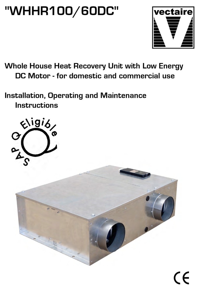
  9. Vectaire WHHR100DC-B Plus Assembly instructions

Vectaire WHHR100DC-B Plus Assembly instructions

9-115016 (&9
# #(&'#)%,"'*'#*"%,
#'#%6#%#!&'"#!!% (&
"&' '#"4$%'"""'""
"&'%('#"&
Page 2
9-11501696

',#'
'&!$#%'"''#%'&"&'%('#""( %( ,#%"&' "#%(&"'$%#('2# #*"
'&"&'%('#"&* "&(%'',#(%)"' '#"&,&'!&"&' 4#!!&&#""(&$%#$% ,"
#"'"(&'##$%'') ,2'% *  "#'  %&$#"& "* "#' $'  ',#%",
!(&'#$%&#"&#%$%#$%','%#( (%'## #*'("$%#)"'&!"( 2'
&#(  *,&)  *''$%#('#%&,%%"2
#(%("'&*'#2'&&"'#%("#"'"(#(& ,2'&&*'#"##%
$# ('"'"!#&'(% ) &!,"%&2
-115016 (&3 5"/125mm spigot, for dwe ings up to 200m2, max capacity 80 /sec
"% "#%!'#"
The Vectaire WHHR100/90DC-B P us heat recovery system pro-
vides who e house mechanica venti ation to iving areas, bedrooms,
kitchen and bathrooms. It extracts sta e, contaminated air from
kitchens, uti ity rooms and bathrooms, and uses the heat recovered
from this air to warm fresh, incoming air to create a f ow of fresh air
throughout the dwe ing. The extract and intake air streams are sep-
arated to avoid contamination.
Heat is rec aimed from extracted air and used, via the heat exchange
process, to warm incoming fresh air. The system wi operate contin-
uous y to create a stab e, comfortab e, hea thy environment avoiding
the use of excessive energy and saving heat a ready generated.
The heat recovery unit wi genera y be insta ed in the oft of a house
or the void above the cei ing in an apartment (but may be insta ed in
a cupboard) and wi be connected by hidden ductwork to vents sited
in the cei ings of the rooms which require venti ation. Each unit is
commissioned individua y a owing its performance to be tai ored to
suit the performance required. There wi be a faci ity to boost the
extraction rate when desired (e.g when cooking or bathing or po utant eve s rise). This may be done automati-
ca y or manua y.
&,&'!&&"'#%("#"'"(#(& ,"&#( &*'#+$'#%!"'""#% '%
%$ !"'2
'(%&
:    who e house heat recovery unit giving continuous venti ation in the kitchen and up to four
additiona wet rooms (using rigid ducting)
:ow noise eve s
:variab e choice ow (trick e) speed and boost options for optimum setting at insta ation
:boost speed can be triggered by a switched ive connection from a variety of externa devices inc uding:
- PIRFF (passive infra red)8
- DRH240 (dynamic remote humidistat)8
- THM (thermostat)8
- a ight switch (if more than one ight switch is used, #"!(&'#( $# &*'7
- a remote switch/pu cord
(8PIRFF, DRH240 and THM may have integra over-run timer which contro s the ength of time that the fan
wi continue to operate at its boost speed after the boost has been switched off.)
:Insta ation MUST be carried out by suitab y qua ified personne and MUST be in accordance with current IEE
regu ations and a appropriate standards and app icab e regu atory guidance.
Page 3
"&' '#"

• This product shou d not be used for any purpose other than that for which it was designed and as shown in
this eaf et
• A packaging shou d be removed and the unit checked for damage in transit. If there is any damage, p ease
contact your supp ier
• The WHHR100/90DC-B P us wi genera y be fitted into a oft of cei ing void. In order to comp y with
Construction (Design & Management) Regu ations, sufficient access for safe maintenance (recommended
on an annua basis), or remova fo owing insta ation, MUST be provided for this product. See dimensions
above.
• Fire Dampers must be fitted to duct work at appropriate ocations in accordance with Bui ding Regu ations
• F ue gases from fue -burning equipment must not be drawn into a iving area. If any room from which air is
extracted contains a fue burning app iance, such as a centra heating boi er, then its f ue must be of the
sea ed or ba anced f ue type, or a owance must be made for an adequate supp y of air into the room.
• The unit is designed for horizonta insta ation and shou d be fitted with 2º ti t towards the condensation
drain used
• The unit must NOT be insta ed:
- where there is excessive oi or grease
- where there are hazardous gases, iquids or vapours that are f ammab e or corrosive
- in ambient temperatures above 60ºC or ower than 5ºC
- in humidity eve s above 90% or in a wet environment
• Where possib e the unit shou d NOT be insta ed direct y above a bedroom or iving room.
• The condensation drain must be fitted and if insu ated, use the equiva ent of at east 25mm of insu ating
materia with a therma conductivity of 0.04 W/(mK)
• Care shou d be taken to ensure that ducting is free from b ockages before switching on the unit as this may
inva idate your guarantee
• Externa gri es shou d be ocated a minimum of 600mm from any f ue out et in accordance with a
Regu ations
:The unit must be connected to a 230-240v, 50Hz sing e phase e ectrica supp y.
• A trip e po e iso ation switch with contact separation of at east 3mm must be used to connect the app iance
to the fixed wiring when using the Switched Live.
.• The product shou d on y be connected to the mains e ectricity supp y or e ectrica out et if:
- your e ectrica vo tage and frequency correspond to those shown on the rating abe .
- the capacity of your e ectricity supp y is sufficient y powerfu to operate the product at its maximum
power
• If one of the spigots is not connected to ducting a safety gri e MUST be fitted to that spigot, so that it is
impossib e for any moving part to be touched.
• This app iance is not suitab e for insta ation on the outside of a bui ding.
Insta ation of the app iance MUST be carried out by a qua ified and suitab y competent person and shou d be
carried out in c ean, dry conditions where dust and humidity are at minima eve s. It shou d on y be insta ed
after other bui ding works have been comp eted and the bui ding in which it is insta ed c eaned. Fai ure to com-
p y with any of the above points wi have an impact on the va idity of the guarantee.
('"('#""'#"& (refer to design drawing)
:4 x 125mm nomina diameter spigots are provided for the connection of ducting. These are c ear y marked
for correct connection of the supp y and exhaust ducts.
:Where ducting is insta ed in an unheated space, a of the ducts shou d be insu ated. Where ducting is in
sta ed in a heated space, on y the co d ducts shou d be insu ated. i.e. the supp y duct from outside and the ex
tract duct from the unit to the outside.
:The duct ayout must be designed to suit the requirements of the venti ation/recovery system and bui ding
ay-out. If the ducting passes through a fire wa /barrier, suitab e fire dampers must be insta ed
:Where rigid duct is used, it shou d be insta ed using the east number of fittings to minimise air f ow resist-
ance. Where possib e, fina connection to the gri es and unit shou d be made with a f exib e connection.
:Where f exib e ducts are used, ensure that:
- duct runs are kept as short as possib e
- the duct is stretched so that it is smooth and straight
- where bends are necessary, they have arge radii (ie avoid sharp bends)
- the duct is not crushed if in a restricted area
#""&'#"
(The unit may sometimes produce condensation which must be drained away. A 15mm dia pipe out et is provid-
ed on this unit).
:A 15mm dia pipe must be fitted to the pipe connection. If any part of the condensate drain is in an
unheated space it MUST be insu ated with the equiva ent of at east 25mm of insu ating materia with a
therma conductivity of 0.04 W/(mK).
:The pipe must drain into the norma househo d drainage system.
:The drain must incorporate a wet or dry trap to prevent air penetration.
:The unit must be ti ted towards the side carryng the condensation exit point. It shou d be insta ed
horizonta y with a 3º ti t towards the condensation drain used (equiva ent of raising the opposite end by
approximate y 25mm).
:The drainage pipe must have a continuous fa from the unit to the drainage co ection point.
 '% #""'#"
3'&$$ "&!(&'%'" *%"!(&'#"#%!'#(%%"'( '#"&"
 $$  &'"%&"( "( '#"&2
• The unit is suitab e for 230V, 50Hz Sing e phase supp y.
• The unit is supp ied with a mains rated 4 core f exib e cord (b ack, brown, grey and green/ye ow)
• A trip e po e iso ation switch with contact separation of at east 3mm must be used to connect the app i-
ance to the fixed wiring when using the Switched Live.
• Boost contro s must not be ocated within 1 metre of a cooker or where they may be affected by
excessive heat or moisture
• Boost contro s shou d be c ear y identified and convenient y ocated.
• The boost speed can be triggered by a switched ive connection from:
- PIRFF (passive infra red)8
- DRH240 (dynamic remote humidistat)8
- THM (thermostat)8
- a ight switch (if more than one ight switch is used, #"!(&'#( $# &*'7
- a remote switch/pu cord
(8PIRFF, DRH240 and THM may have integra over-run timer which contro s the ength of time that the fan
wi continue to operate at its boost speed after the boost has been switched off.)
Page 4
#!!&&#""
:The units operate by extracting hot, sta e air from kitchens, WCs, bathrooms etc, and passing it into a heat
exchanger and out to the atmosphere. Another fan draws in coo , fresh air and passes it through the same
heat exchanger, where it heated by the outgoing, sta e air.
:When the unit is set up and running, the minimum setting on the speed contro switch must re ate to the
designed vo ume air f ow. The variab e air f ow from minimum to maximum a ows the unit to extract a
greater vo ume to cope with any increase in the bui d up of condensation or fou air, ie cooking etc.
:Before starting the commissioning procedure, refer to the design drawing for correct air f ows.
2 extract and supp y air vo umes wi not a ways be equa . When setting up, therefore, the extract system
shou d be the datum.
Insta ation of the app iance  be carried out by a qua ified and suitab y competent person and shou d be car-
ried out in c ean, dry conditions where dust and humidity are at minima eve s. It shou d on y be insta ed after other
bui ding works have been comp eted and the bui ding in which it is insta ed c eaned. Fai ure to comp y with any of the
above points wi have an impact on the va idity of the guarantee.
#!!&&#""%#(%
:Ensure that the exhaust and supp y gri es or va ves are fu y open.
:Turn the e ectrica supp y ON and set the fan speed contro to trick e mode (switched ive off).
:Check the airf ow at the extract air va ves or gri es and compare to the design va ue. If incorrect, adjust as
fo ows:-
- Turn the e ectrica supp y off.
- Remove the cover of the e ectrica contro pane .
- Adjust the potentiometer marked ‘min’ up or down as required. (See page 6)
- Turn on the e ectrica supp y and recheck the airf ows.
- Re-adjust as above, if necessary.
- Make any fina adjustments at the air va ve by rotating the centre section.
:Switch the unit to boost mode by connecting the switched ive. Measure the airf ow and adjust the boost air
f ow by fo owing the procedure above using the ‘max’ potentiometer. (Do not make any further adjustments
at the air va ve).
:Rep ace the contro er cover.
 """"'""
3("'(&&./1&($$ ,"#"'"&%#''"!" $%'&2
: #%%%,"#('",!"'""#% ""#$%'#"&'!"& '% &($$ ,&6
#""'.
• '+"%!"'""!(&'#"$%#&&#" ,2#"'''%%)$%'!"'#%
)2
• The air fi ters of the Vectaire WHHR100/90DC-B P us shou d be c eaned regu ar y by a suitab y qua ified
person (the frequency of c eaning wi vary depending on the insta ation environment).
# "' '%&
• Remove the main access pane
• Remove the rubber inserts from the fi ter s ots (where fitted) and s ide out the fi ters from the interna
mou dings.
• C ean the fi ters carefu y using a vacuum c eaner and refit.
• Rep ace the rubber inserts into the s ots.
• Rep ace the access pane and ensure it is secure y ocated.
• Power to the unit can now be restored.
 '%$ !"'
Fi ters shou d be c eaned annua y and rep aced when heavi y contaminated.
Rep acement fi ters are avai ab e from Vectaire - ca us on +44 (0) 1494 522333 or via
sa [email protected]
Page 5
Page 6
Vectaire Ltd, Lincoln Road, Cressex Business Park, Hi h Wycombe, Buckin hamshire, HP12 3RH
Tel: +44 (0)1494 522333. Fax: +44 (0)1494 522337. Email: [email protected]
WHHR100/90DC-B Plus-Oct 2014 E & O.E
</337238"*(<
.&((#%"(
%"%*()%+'.$),)%,$'.
%)%'8%'%#()$%##'"*(
$()"")%$6&')$$$)$$
$()'*)%$(
Page 2
</337238<8


).%)
)(#&%')$))%')($()'*)%$$*"'*"".%'$()""$%'*($)&'%*)4%""%,$
)($()'*)%$(,""$(*')).%*'+$)")%$(.()#($()""6%##((%$$*(&'%&'".$
%$)$*()%%&'))+".4)' ,"" $%) "'(&%$("$,""$%) &) "").%'$.
#*()%&'(%$(%'&'%&').)'%*"*')%%""%,)*$&'%+$)(#$*"4)
(%*"",.(+"",))&'%*)%'(.''$4
%*'*$)(,)%4)(($)%'*$%$)$*%*(".4)((,)%$%%'
&%""*)$)$#%()*'"+"(#.$'(4
/337238"*(.&((5 5"/125mm spigot, for dwellings up to 200m2, max capacity 80 l/sec
$'"$%'#)%$
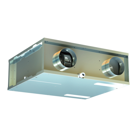
The Vectaire WHHR100/90DC-B Plus Bypass heat recovery system
provides whole house mechanical ventilation to living areas, bed-
rooms, kitchen and bathrooms. It extracts stale, contaminated air
from kitchens, utility rooms and bathrooms, and uses the heat recov-
ered from this air to warm fresh, incoming air to create a flow of fresh
air throughout the dwelling. The extract and intake air streams are
separated to avoid contamination.
Heat is reclaimed from extracted air and used, via the heat exchange
process, to warm incoming fresh air. The system will operate contin-
uously to create a stable, comfortable, healthy environment avoiding
the use of excessive energy and saving heat already generated.
The heat recovery unit will generally be installed in the loft of a house
or the void above the ceiling in an apartment (but may be installed in
a cupboard) and will be connected by hidden ductwork to vents sited
in the ceilings of the rooms which require ventilation. Each unit is
commissioned individually allowing its performance to be tailored to
suit the performance required. There will be a facility to boost the extraction rate when desired (e.g when cook-
ing or bathing or pollutant levels rise). This may be done automatically or manually.
(.()#(($)%'*$%$)$*%*(".$(%*"(,)%-&)%'#$)$$%'")'
'&"#$)4
)*'(
= "" whole house heat recovery unit giving continuous ventilation in the kitchen and up to four
additional wet rooms (using rigid ducting)
=low noise levels
=variable choice low (trickle) speed and boost options for optimum setting at installation
=boost speed can be triggered by a switched live connection from a variety of external devices including:
- PIRFF (passive infra red);
- DRH240 (dynamic remote humidistat);
- THM (thermostat);
- a light switch (if more than one light switch is used, %$#*()%*"&%"(,):
- a remote switch/pull cord
(;PIRFF, DRH240 and THM may have integral over-run timer which controls the length of time that the fan
will continue to operate at its boost speed after the boost has been switched off.)
=Installation MUST be carried out by suitably qualified personnel and MUST be in accordance with current IEE
regulations and all appropriate standards and applicable regulatory guidance.
Page 3
$()"")%$

• This product should not be used for any purpose other than that for which it was designed and as shown in
this leaflet
• All packaging should be removed and the unit checked for damage in transit. If there is any damage, please
contact your supplier
• The WHHR100/90DC-B Plus Bypass will generally be fitted into a loft of ceiling void. In order to comply
with Construction (Design & Management) Regulations, sufficient access for safe maintenance (recom
mended on an annual basis), or removal following installation, MUST be provided for this product. See
dimensions above.
• Fire Dampers must be fitted to duct work at appropriate locations in accordance with Building Regulations
• Flue gases from fuel-burning equipment must not be drawn into a living area. If any room from which air is
extracted contains a fuel burning appliance, such as a central heating boiler, then its flue must be of the
sealed or balanced flue type, or allowance must be made for an adequate supply of air into the room.
• The unit is designed for horizontal installation and should be fitted with 2º tilt towards the condensation
drain used
• The unit must NOT be installed:
- where there is excessive oil or grease
- where there are hazardous gases, liquids or vapours that are flammable or corrosive
- in ambient temperatures above 60ºC or lower than 5ºC
- in humidity levels above 90% or in a wet environment
• Where possible the unit should NOT be installed directly above a bedroom or living room.
• The condensation drain must be fitted and if insulated, use the equivalent of at least 25mm of insulating
material with a thermal conductivity of 0.04 W/(mK)
• Care should be taken to ensure that ducting is free from blockages before switching on the unit as this may
invalidate your guarantee
• External grilles should be located a minimum of 600mm from any flue outlet in accordance with all
Regulations
=The unit must be connected to a 230-240v, 50Hz single phase electrical supply.
• A triple pole isolation switch with contact separation of at least 3mm must be used to connect the appliance
to the fixed wiring when using the Switched Live.
.• The product should only be connected to the mains electricity supply or electrical outlet if:
- your electrical voltage and frequency correspond to those shown on the rating label.
- the capacity of your electricity supply is sufficiently powerful to operate the product at its maximum
power
• If one of the spigots is not connected to ducting a safety grille MUST be fitted to that spigot, so that it is
impossible for any moving part to be touched.
• This appliance is not suitable for installation on the outside of a building.
Installation of the appliance MUST be carried out by a qualified and suitably competent person and should be
carried out in clean, dry conditions where dust and humidity are at minimal levels. It should only be installed
after other building works have been completed and the building in which it is installed cleaned. Failure to com-
ply with any of the above points will have an impact on the validity of the guarantee.
*)$*)%$$)%$( (refer to design drawing)
=4 x 125mm nominal diameter spigots are provided for the connection of ducting. These are clearly marked
for correct connection of the supply and exhaust ducts.
=Where ducting is installed in an unheated space, all of the ducts should be insulated. Where ducting is in
stalled in a heated space, only the cold ducts should be insulated. i.e. the supply duct from outside and the ex
tract duct from the unit to the outside.
=The duct layout must be designed to suit the requirements of the ventilation/recovery system and building
lay-out. If the ducting passes through a fire wall/barrier, suitable fire dampers must be installed
=Where rigid duct is used, it should be installed using the least number of fittings to minimise air flow resist-
ance. Where possible, final connection to the grilles and unit should be made with a flexible connection.
=Where flexible ducts are used, ensure that:
- duct runs are kept as short as possible
- the duct is stretched so that it is smooth and straight
- where bends are necessary, they have large radii (ie avoid sharp bends)
- the duct is not crushed if in a restricted area
%$$()%$
(The unit may sometimes produce condensation which must be drained away. A 15mm dia pipe outlet is provid-
ed on this unit).
=A 15mm dia pipe must be fitted to the pipe connection. If any part of the condensate drain is in an
unheated space it MUST be insulated with the equivalent of at least 25mm of insulating material with a
thermal conductivity of 0.04 W/(mK).
=The pipe must drain into the normal household drainage system.
=The drain must incorporate a wet or dry trap to prevent air penetration.
=The unit must be tilted towards the side carryng the condensation exit point. It should be installed
horizontally with a 3º tilt towards the condensation drain used (equivalent of raising the opposite end by
approximately 25mm).
=The drainage pipe must have a continuous fall from the unit to the drainage collection point.
")'"%$$)%$
5)(&&"$(#*()')$"",'$#*()%$%'#)%*''$)*")%$($
""&&""()$'($*"$*")%$(4
• The unit is suitable for 230V, 50Hz Single phase supply.
• The unit is supplied with a mains rated 4 core flexible cord (black, brown, grey and green/yellow)
• A triple pole isolation switch with contact separation of at least 3mm must be used to connect the appli-
ance to the fixed wiring when using the Switched Live.
• Boost controls must not be located within 1 metre of a cooker or where they may be affected by
excessive heat or moisture
• Boost controls should be clearly identified and conveniently located.
• The boost speed can be triggered by a switched live connection from:
- PIRFF (passive infra red);
- DRH240 (dynamic remote humidistat);
- THM (thermostat);
- a light switch (if more than one light switch is used, %$#*()%*"&%"(,):
- a remote switch/pull cord
(;PIRFF, DRH240 and THM may have integral over-run timer which controls the length of time that the fan
will continue to operate at its boost speed after the boost has been switched off.)
Page 4
Page 5
%##((%$$
1. The commissioning must only be carried
out by a suitably qualified person.
2. Prior to starting the commissioning pro-
cedure, ensure that the ductwork con-
nections and airflow directions match
one of the options A or B, shown on
page 3. Check that the drain connection
is on the correct side.
3. Before making any ad ustments, ensure
that the air valves or grilles are fully open.
4. Motor speed and timer settings are ad-
usted on the control board, which is lo-
cated behind the access panel Once
removed, there is access to potentiome
ters and umper switches for use during
the commissioning process. (See dia
gram on Page 8)
5))%$)'%"%'&$"
'#%+6013+%")"+%$$)%$('
(("4
'"%, *()#$)%')8$'$
The supply and extract motors are ad usted separately for both the normal (trickle) speed and boost speed.
The set-up procedure is as follows :-
1. For right-hand drainage as shown on Page 5, ensure that the umper switch JP4 (see diagram below)
is in %()%$
%'#"9)'!":&9'7'$:
2. Before making any ad ustments, switch on the unit at trickle speed. 5013+%")6"+#$('
&'($)%$)'*)%'4 Move the speed ad ust umper switch JP5, to position A, as shown in the
diagram. A green light will appear on the circuit board.
3. With the boost switch OFF (bathroom light switch off), measure the airflow rate at the extract valve and
compare this to the design value. If there is a difference, ad ust the potentiometer MIN-MOT2 , on the con-
trol board and re-check the airflow rate. If the value is slightly higher than that required, final ad ustment
can be made at the air valve.
4. Set the position of the potentiometer MIN-MOT1 to the same as MIN-MOT2.
5. Measure the airflow at the supply valve. This should be the same or slightly lower than the extract rate;.
If higher, reduce the airflow by ad usting MIN-MOT1. Final minor ad ustments can be made at the air valve.
;unless a different supply value has been specified.
%%()&9'7'$:
6. Switch on the boost (light switch ON).
7. Measure the airflow rate at the extract valve and compare this to the design value. If there is a difference,
ad ust the potentiometer MAX-MOT2.
8. Re-check the airflow rate and make further ad ustments at MAX-MOT2 until correct. %$%)'8 *())
'+"+4
9. Set the position of the potentiometer MAX-MOT1 to the same as MAX-MOT2.
10. Measure the airflow at the supply valve. This should be the same or slightly lower than the extract rate.;
If higher, reduce the airflow by ad usting MAX-MOT1 until correct. %$%)'8 *())'+"+.
;unless a different supply value has been specified.
11. Return the speed ad ust umper switch JP5, to position B (green light goes out)
Page 6
'"%, *()#$)%')8$'$
1. For left hand drainage as shown on Page 5, ensure that the umper switch JP4 (see diagram above) is in
%()%$4
%'#"9)'!":&9"7'$:
2. Before making any ad ustments, switch on the unit at trickle speed. 5013+%")6"+#$('
&'($)%$)'*)%'4 Move the speed ad ust umper switch JP5, to position A, as shown in the
diagram. A green light will appear on the circuit board.--
3. With the boost switch OFF (bathroom light switch off), measure the airflow rate at the extract valve and
compare this to the design value. If there is a difference, ad ust the potentiometer MIN-MOT1, on the con-
trol board and re-check the airflow rate. If the value is slightly higher than that required, final ad ustment
can be made at the air valve.
4. Set the position of the potentiometer MIN-MOT2 to the same as MIN-MOT1.
5. Measure the airflow at the supply valve. This should be the same or slightly lower than the extract rate
(
unless a different supply value has been specified
). If higher, reduce the airflow by ad usting MIN-MOT2.
Final, minor ad ustments can be made at the air valve.
%%()&9"7'$:
6. Switch on the boost (light switch ON).
7. Measure the airflow rate at the extract valve and compare this to the design value. If there is a difference,
ad ust the potentiometer MAX-MOT1.
8. Re-check the airflow rate and make further ad ustments at MAX-MOT1 until correct. %$%)'8 *())
'+"+4
9. Set the position of the potentiometer MAX-MOT2 to the same as MAX-MOT1.
10. Measure the airflow at the supply valve. This should be the same or slightly lower than the extract rate.;
If higher, reduce the airflow by ad usting MAX-MOT2 until correct. %$%)'8 *())'+"+.
;unless a different supply value has been specified.
11. Return the speed ad ust umper switch JP5, to position B (green light goes out)
#'+''*$ *()#$)
After the boost switch has been turned off, the fan will continue to run at boost speed for up to 20 minutes.
This overrun time is ad ustable using the potentiometer marked TIMER. The time can be varied between 0 and
20
minutes. After the set time, the fan returns to normal speed.
".8%$%%()
When the boost switch is operated, the boost speed activation can be delayed by 2 minutes, if required.
Using the umper switch JP6, move the umper position to either:-
- 2 minutes, or
- 0.5 seconds
Finally, replace the control panel cover securely.
%$)'%""' *()#$)'#
"$$$$)$$
5*$)*((013(*&&".$%$)$('%))$#$"&')(4
=%'''.$%*)$.#$)$$%'"$$%&')%$()#$(")'"(*&&".(8
%$$).
• )-$'#$)$$#*()%$&'%((%$"".4%$)))''+&')#$)%'
+4
• The air filters of the Vectaire WHHR100/90DC-B Plus should be cleaned regularly by a suitably qualified
person (the frequency of cleaning will vary depending on the installation environment).
%"$)")'(
• Remove the main access panel
• Remove the rubber inserts from the filter slots (where fitted) and slide out the filters from the internal
mouldings.
• Clean the filters carefully using a vacuum cleaner and refit.
• Replace the rubber inserts into the slots.
• Replace the access panel and ensure it is securely located.
• Power to the unit can now be restored.
")'&"#$)
Filters should be cleaned annually and replaced when heavily contaminated.
Replacement filters are available from Vectaire - call us on +44 (0) 1494 522333 or via
[email protected]
Page 7
Vectaire Ltd, Lincoln Road, Cressex Business Park, Hi h Wycombe, Buckin hamshire, HP12 3RH
Tel: +44 (0)1494 522333. Fax: +44 (0)1494 522337. Email: [email protected]
WHHR100/90DC-B Plus Bypass-Mayt 2016 E & O.E

This manual suits for next models

2

Other Vectaire Heating System manuals

Vectaire EVO350DC Operating and maintenance manual

Vectaire

Vectaire EVO350DC Operating and maintenance manual

Vectaire Mini DC Assembly instructions

Vectaire

Vectaire Mini DC Assembly instructions

Vectaire EVO250DC Assembly instructions

Vectaire

Vectaire EVO250DC Assembly instructions

Vectaire Studio Assembly instructions

Vectaire

Vectaire Studio Assembly instructions

Vectaire WHHR Maxi Assembly instructions

Vectaire

Vectaire WHHR Maxi Assembly instructions

Vectaire WHHR125DC Assembly instructions

Vectaire

Vectaire WHHR125DC Assembly instructions

Vectaire WHHR125DC Assembly instructions

Vectaire

Vectaire WHHR125DC Assembly instructions

Vectaire EVO90DC Assembly instructions

Vectaire

Vectaire EVO90DC Assembly instructions

Vectaire WHHR125DC Assembly instructions

Vectaire

Vectaire WHHR125DC Assembly instructions

Vectaire WHHR Midi Assembly instructions

Vectaire

Vectaire WHHR Midi Assembly instructions

Vectaire WHHR100/60DC Assembly instructions

Vectaire

Vectaire WHHR100/60DC Assembly instructions

Vectaire EVO220DC Assembly instructions

Vectaire

Vectaire EVO220DC Assembly instructions

Vectaire WHHRC180DC Assembly instructions

Vectaire

Vectaire WHHRC180DC Assembly instructions

Popular Heating System manuals by other brands

Vent-Axia Sentinel Kinetic 200ZH Installation & commissioning

Vent-Axia

Vent-Axia Sentinel Kinetic 200ZH Installation & commissioning

Velux CLI U12 SD0(W/L/F/P) 118 El B/U instruction manual

Velux

Velux CLI U12 SD0(W/L/F/P) 118 El B/U instruction manual

Aqua-Hot AHE-600-D03 Service manual

Aqua-Hot

Aqua-Hot AHE-600-D03 Service manual

therm-ic POWERGLOVES Instructions for use

therm-ic

therm-ic POWERGLOVES Instructions for use

Robertshaw 720 Series Installation data

Robertshaw

Robertshaw 720 Series Installation data

Robur CALDARIA CONDENSING 100 Installation and use instructions

Robur

Robur CALDARIA CONDENSING 100 Installation and use instructions

Mitsubishi Electric Ecodan HUS210FTC4ST installation manual

Mitsubishi Electric

Mitsubishi Electric Ecodan HUS210FTC4ST installation manual

Baxi 755 Installer's guide

Baxi

Baxi 755 Installer's guide

jbc PHSK PHSE-1KB instruction manual

jbc

jbc PHSK PHSE-1KB instruction manual

Hydro-Hot HHE-200-09E owner's manual

Hydro-Hot

Hydro-Hot HHE-200-09E owner's manual

Watts Push'n'Go HKV-R Series Installation and operating manual

Watts

Watts Push'n'Go HKV-R Series Installation and operating manual

Viessmann Divicon installation instructions

Viessmann

Viessmann Divicon installation instructions

Robur GAHP Series Installation, use and maintenance manual

Robur

Robur GAHP Series Installation, use and maintenance manual

Polypipe Under Floor Heating Systems Technical installation manual

Polypipe

Polypipe Under Floor Heating Systems Technical installation manual

HEATIZON SYSTEMS Gutter Melt SR Design & Installation Manual

HEATIZON SYSTEMS

HEATIZON SYSTEMS Gutter Melt SR Design & Installation Manual

Monitor Products, Inc M2400 Service manual

Monitor Products, Inc

Monitor Products, Inc M2400 Service manual

Rinnai Demand Duo CHS199100CUiP Installation and operation manual

Rinnai

Rinnai Demand Duo CHS199100CUiP Installation and operation manual

adept technology HM140/1 installation manual

adept technology

adept technology HM140/1 installation manual

manuals.online logo
manuals.online logoBrands
  • About & Mission
  • Contact us
  • Privacy Policy
  • Terms and Conditions

Copyright 2025 Manuals.Online. All Rights Reserved.