Solar Xantrex 784-0110 User manual

Installation Guide
110W Solar Max Flex Panel
Model Number: 784-0110
110W Solar Max Flex Slim Panel
Model Number: 784-0110S
220W Solar Max Flex Panel
Model Number: 784-0220
330W Solar Max Flex Panel
Model Number: 784-0330
NOTE: Actualproduct may be different from what isshown.
Thank you for purchasing the Xantrex Solar Max Flex Panel. The Xantrex Solar Max Flex Panel is a
high quality, carbon emissions-free, and sustainable power source for your vehicle such as,
recreational vehicle (RV), truck, or boat. It is designed to take solar energy and quietly produce power
for your vehicle's DC appliances and store energy to a battery during daylight hours.
The Solar Max Flex Panel base package includes the
following items:
none Solar Max Flex Panel
none Product Notice with a link to this Installation
Guide
NOTE: If any of the accessories, materials, and other
items are missing, contact Xantrex or any authorized
Xantrex dealer for replacement. See Contact Information
on the back cover.
The following Xantrex accessories are available to complete your solar system and are sold
separately:
nSolar and Battery Cables Starter Kit (PN:708-0150)
nPWM 30A Charge Controller (PN:709-3024-01)
nMPPT 30A Charge Controller (PN:710-3024-01)
nMPPT Remote Display (PN:710-0010)

Safety Information
Important Information
READ AND SAVE THIS INSTALLATION GUIDE FOR FUTURE REFERENCE.
Read these instructions carefully and look at the equipment to become familiar with the device before
installing, operating, configuring, maintaining, and troubleshooting it. The following special messages
may appear throughout this documentation or on the equipment to warn of potential hazards or to call
attention to information that clarifies or simplifies a procedure.
The addition of either symbol to a “Danger” or “Warning” safety label indicates that
an electrical hazard exists which will result in personal injury if the instructions are
not followed.
This is the safety alert symbol. It is used to alert you to potential personal injury
hazards. Obey all safety messages that follow this symbol to avoid possible injury
or death.
Product Safety Information
cBefore using the solar max flex panel, read all instructions and cautionary markings on the
solar max flex panel's components, the batteries, and all appropriate sections of this guide.
cUse of accessories not recommended or sold by the manufacturer may result in injury to
persons, a risk of electric shock, or a risk of fire.
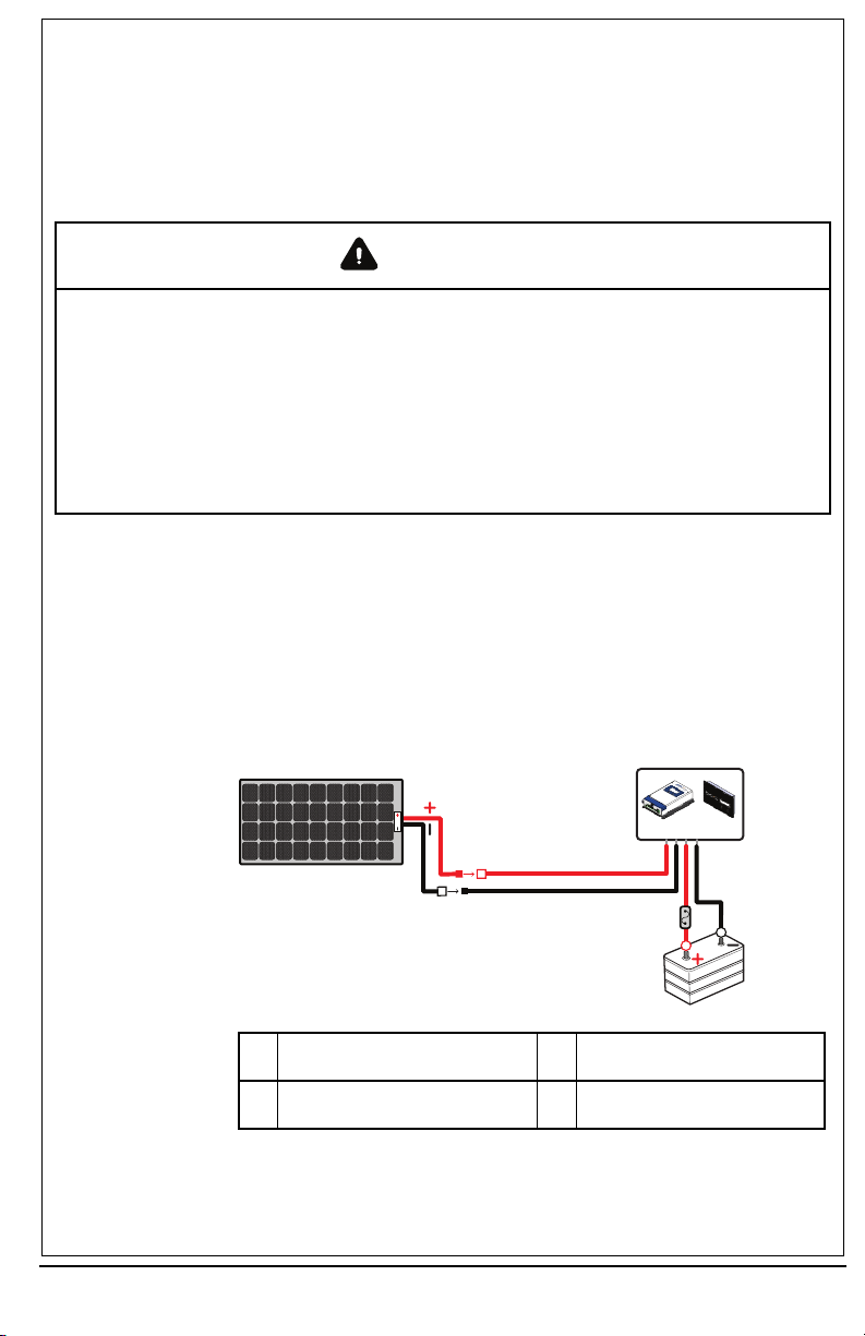
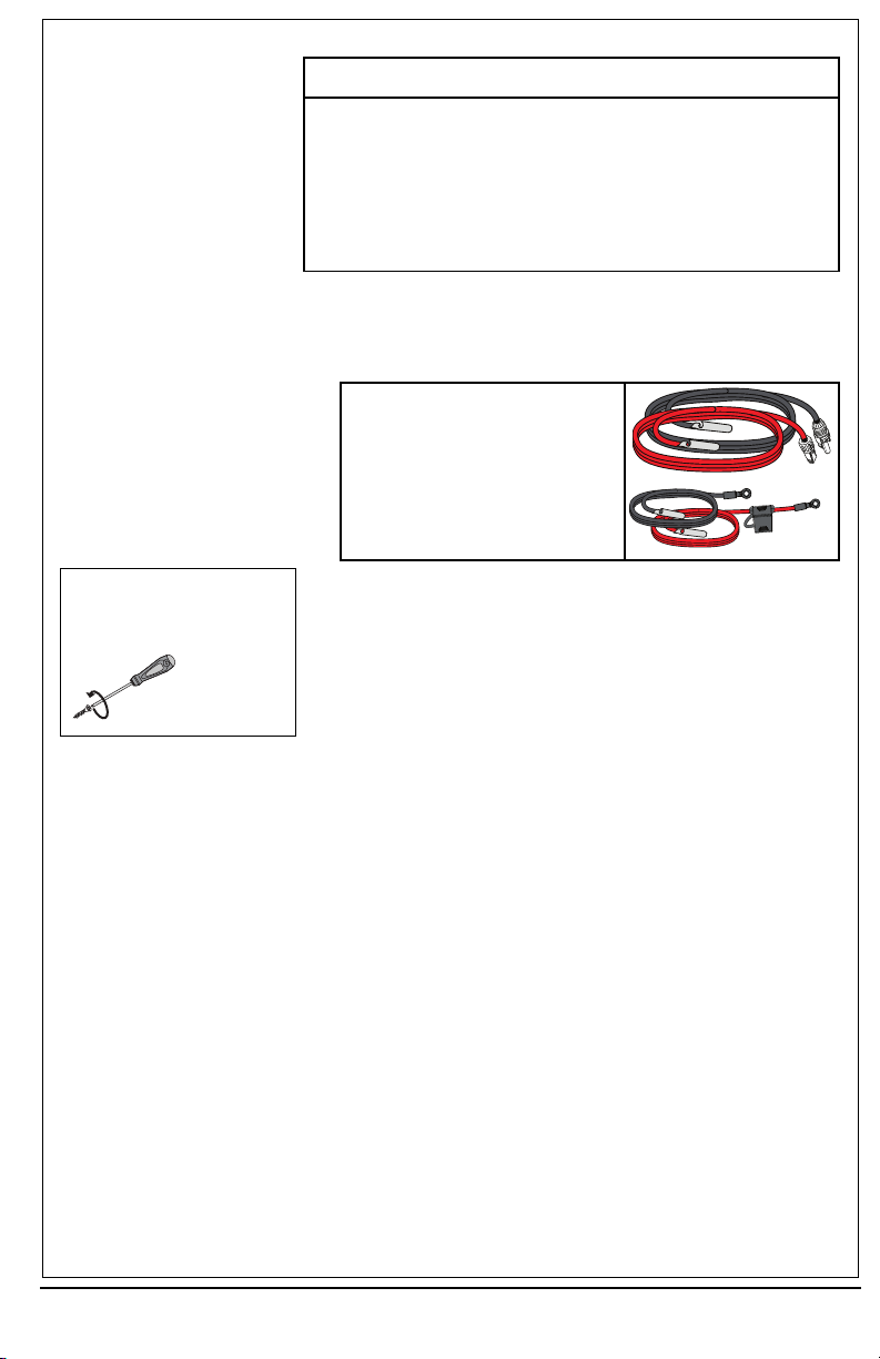
cThe solar max flex panel is designed to be connected to your DC electrical systems. The
manufacturer recommends that all wiring be done by a certified PV technician or electrician to
ensure adherence to the local and national electrical codes applicable in your jurisdiction.
cTo avoid a risk of fire and electric shock, make sure that existing wiring is in good condition and
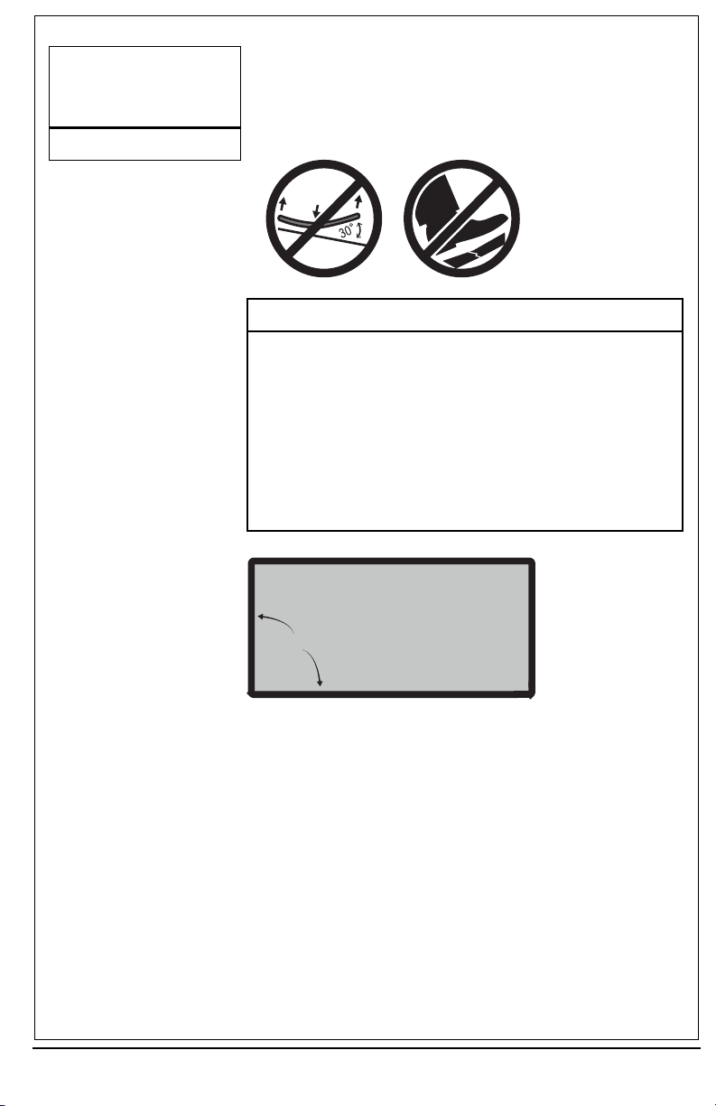
that wire is not undersized. Do not operate the solar max flex panel with damaged or
substandard wiring.
cDo not operate the solar max flex panel if it has been damaged in any way.
cThis solar max flex panel does not have any user-serviceable parts. Do not disassemble the
solar max flex panel except where noted for connecting wiring and cabling. See your warranty
for instructions on obtaining service. Attempting to service the solar max flex panel yourself may
result in a risk of electrical shock or fire.
cTo reduce the risk of electrical shock, disconnect the solar max flex panel from all devices and or
components before attempting any maintenance or cleaning on the solar max flex panel.
cTo reduce the chance of short-circuits, always use insulated tools when installing or working
with this equipment.
cRemove personal metal items such as rings, bracelets, necklaces, and watches when working
with electrical equipment.
cDo not ground any PV conductors.
cDo not install the solar panel on top of a residential structure.
Copy right© 2022 X antr ex LLC. All Rights Reserv ed.A ll trademarks are owned by Xantrex LLC and its affiliates.
Exclusion for Documentation
UNLE SS S PE CIFICA LLY AGREE D TO IN WRITING, SE LLER
(A ) MAK ES NO WARRA NTY AS TO THE ACCURACY ,S UFFICIENCY OR SUITAB ILITY OF ANY TECHNICAL OR OTHER INFORMA TION PROVIDED IN ITS MANUA LS OR OTHER
DOCUMENTATION;
(B ) A SSUMES NO RESPONS IBILITY OR LIAB ILITY FOR LOSS E S, DAMAGES , COSTS OR EXP ENS ES, WHETHER S PECIAL,DIRECT,INDIRECT,CONSEQUE NTIA L OR INCIDENTAL,
WHICH MIGHT A RIS E OUT OF THE US E OF S UCH IN FORMATION. TH E US E OF ANY S UCH INFORMATION WILL B E E NTIRE LY AT THE US ER’S RISK ; AND
(C) RE MINDS YOU THAT IF THIS MANUAL IS IN ANY LANGUAGE OTHER THAN ENGLIS H, ALTHOUGH STEP S HAV E BE E N TAK EN TO MAINTAIN THE A CCURA CY OF THE TRANSLATION,
THE A CCURACY CANNOT BE GUA RA NTEE D. APP ROVED CONTENT IS CONTAINED WITH THE E NGLISH LANGUA GE V E RS ION WHICH IS POSTED A T http://www.xantrex.com.
NOTE:Visithttp://www.xantrex.com , click Products,selecta P roduct category,selecta P roduc t,and search the Produc t Documents panel for a translation ofthe English guide, if av ailable.
Contact Information
Telephone: +1-800-670-0707 /+1-408-987-6030 Web: http://www.xantrex.com
Email: customerserv[email protected],
http://www.xantrex.com/power-products-s upport/
2 975-1029-01-01 Rev B
June 2022

This page is intentionally blank.

Basic Installation Steps
Safety Instructions
Before beginning your installation:
nRead this entire Installation section so you can plan the installation from beginning to end.
nAssemble all the tools and materials you require for the installation.
nBe aware of all safety and electrical codes which must be met.
WARNING
ELECTRICAL SHOCK AND FIRE HAZARD
nThe power system must be designed by a certified vehicle solar system designer and installed
by a certified solar system technician.
nAll wiring should be done by qualified personnel to ensure compliance with all applicable
installation codes and regulations.
nDisconnect all power sources.
nDisable and secure disconnect devices.
Failure to follow these instructions can result in death, serious injury, or equipment
damage
Tools and Materials
You may need the following tools to install the Solar Max Flex Panel:
nWrench set
nTorque driver
1.Plan the power system and where to mount the solar panel.
a. The Xantrex Solar Max Flex Panel comes in the following power levels:
110 W standard, 110 W slim, 220 W, and 330 W
b. Draw your power system on paper similar to Figure 1 .
Figure 1 Cable Schematic
1
2
4
3
1Solarpanel
See section on Solar PanelWiring formore
information.
3DC fuse (or batterydisconnect)
2Charge controller (PWM or MPPT)
See section on Solar PanelWiring formore
information.
4Battery(12Vor24V)
975-1029-01-01 Rev B
June 2022
5

2.Plan where to mount the charge controller, fuses, and cable locations.
a. Identify and gather information about your vehicle.
-Some vehicles are factory-installed with roof cable entry
points.
-If a cable entry point is absent, factory-installed vents can be
used to route cables through.
b. Locate a suitable location for the charge controller inside the
vehicle. Select an area that is readily accessible, viewable, and
free from exposure to moisture.
c. Plan the route and measure the lengths of cables needed to
reach their connection points factoring in bends and slack.
d. You may add additional solar panels. For more information,
see Solar Panel Wiring on page 10.
WARNING
ELECTRIC SHOCK AND FIRE HAZARD
Do not ground any PV conductors.
Failure to follow these instructions can result in death,
serious injury, or equipment damage.
PWM 30A Charge Controller (PN: 709-3024-01)
[[[Undefined variable XantrexVariables.Accessory
10]]]
6 975-1029-01-01 Rev B
June 2022

3.Mount the solar panel.
TIP: Once applied to a surface, the 3M™
VHB™ tape, which isa high-strength, double-
sided acrylic adhesive tape, cannot be easily
removed without damaging both the solar
paneland the mounting surface. For more
information, visit the 3M website.
IMPORTANT: Follow the recommendations
illustrated in Figure 2 and succeeding Figures.
a. Unpack the solar panels and prepare all installation tools and
materials.
b. Prepare the roof mounting surface by removing dust, dirt, and
debris. Clean and degrease the roof surface with isopropyl
alcohol and dry completely.
Figure 2 Precautions
NOTICE
GENERAL PRECAUTIONS
lDo not bend more than 30° when handling and mounting the
solar panel.
lDo not step on the solar panel.
lDo not mount the solar panel near other roof fixtures that can
obstruct direct exposure to sunlight.
lSelect the mounting area carefully and mark the exact and
intended location of the solar panel.
Failure to follow these instructions can result in physical
damage to vehicles and property.
Figure 3 Adhesive strips on the panel's backside
all sides adhesive
all surface adhesive
The backside of the SolarMaxFlex Panelhas 3M VHBtape strips already applied around the perimeterof the
panel.
c. Peel off the liner film from the 3M VHB tape and place the Solar
Max Flex Panel on the exact and intended location. It is ideal to
have two people to carefully and accurately mount the solar
panel.
d. Apply even pressure only on top of the areas where there is the
3M VHB tape underneath the solar panel for proper bonding of
the 3M VHB tape to the mounting surface. It is ideal to use a
roller or the palm of your hands to apply pressure.
e. Be careful not to apply hard pressure on the solar cells that may
lead to damage.
975-1029-01-01 Rev B
June 2022
7

TIP: Use a 2"-wide 3M 4411 Extreme Sealing
Tape to applyallaround the sides of the panel
for a tighter seal. For more information, visit the
3M website.
Figure 4 Adhesive placement depending on surface
sealing tape
For illustration purposes. The solar cellsare shown as perspective only. Do not applythe adhesive tape on top of
the solar cells. The adhesive tape must be applied on the backside of the paneland onto the mounting surface.
8 975-1029-01-01 Rev B
June 2022

4.Connect the DC cables.
NOTICE
REVERSE POLARITY
Check polarity at all terminals before making the final DC
connection. Pos(+) (red) must connect to charge controller pos(+)
(red); Neg(–) (black) must connect to charge controller neg(–)
(black).
Failure to follow these instructions can result in equipment
damage.
a. Cover the solar panel with a blanket (or the packaging box) to
de-energize it.
b. Connect the red pos (+) and black neg (–) PV cables to the
solar panel using the MC4-type connectors.
Solar and Battery Cables Starter
Kit 10 AWG, 20-ft PV cables, 10-ft
battery cables (PN: 708-0150)
T3:
10.6 lb-in
Torque
1.2 N-m
c. Route the PV cables through the roof entry point and connect
the red pos (+) and black neg (–) PV cables to the charge
controller. See T3.
d. Connect the red pos (+) and black neg (–) battery cables to the
charge controller. See T3.
e. Route the battery cable inside the vehicle and connect the red
pos (+) and black neg (–) battery cables to the respective
battery terminals.
f. Secure all cables with clamps (and/or cable ties) and additional
strain-relief as necessary.
g. Clear the roof and the cable routes of tools and other debris
that may have been left during installation.
5.Operate and maintain the system.
a. Remove the blanket (or the packaging box) covering the solar
panel to start energizing the solar panel.
b. Refer to Solar Panel Maintenance and Care on page 12 for
best practices.
975-1029-01-01 Rev B
June 2022
9

Solar Panel Wiring
a. Depending on your power needs and installation type, you have two kinds of solar charge
controllers available.
Solar Charge Controller Amp Output Voltage Part Number
Pulse width modulation 30A 12/24VDC 709-3024-01
Maximum power point tracking 30A 12/24VDC 710-3024-01
b. Solar panels can be configured in series, parallel, or a combination of both series and parallel.
Figure 5 Cable schematic for series
Pos(+) of first panel connects to Neg(-) of next panel and so on and terminating with the Pos(+)
of the solar charge controller.
Neg(-) of first panel extends to Neg(-) terminal of the solar charge controller.
Optimized for MPPT solar charger.
10 975-1029-01-01 Rev B
June 2022

Figure 6 Cable schematic for parallel
Pos(+) of first panel connects to Pos(+) of next panel using branch connectors and so on and
terminating with the Pos(+) of the solar charge controller.
Neg(-) of first panel connects to Neg(-) of next panel using branch connectors and so on and
terminating with the Neg(-) of the solar charge controller.
Optimized for MPPT or PWMsolar charger.
Figure 7 Cable schematic for combination
One set of panels connect in series to form one string and so on.
Two or more strings connect in parallel.
Optimized for MPPT solar charger.
975-1029-01-01 Rev B
June 2022
11

Solar Panel Maintenance and Care
Although a well designed vehicle-mounted solar system requires minimal maintenance, it is highly
recommended to perform an inspection and cleaning of the solar panels during the warranty period.
This helps to ensure optimal system performance and reliability through a few simple steps.
Visual
Inspection
Perform a visual inspection of the solar system on a monthly basis to identify if there are
any visual defects or improper connections.
nCheck for any sharp objects on the solar panel surface.
nCheck for any signs of corrosion or burnt hotspots around the solar cell and
backsheet area.
nCheck that the solar panel is clear of any shading by any foreign material or
unwanted obstacles. Just a small amount of shade on the solar panel surface can
cause significant power output loss.
nIf the solar panel has slight discoloration over a period of usage, this is considered
normal for solar panels that use an anti-reflection coating laminate.
Cleaning
Solar
Panels
The power output of a solar panel is proportional to the amount of sunlight that reaches
the solar cells. Therefore, any build-up of dust or dirt on the surface of the solar panel will
result in a loss of power. This is a trade-off between the maximizing the power output of
the solar panel versus the cost and time to perform regular cleaning.
cDo not clean solar panels if there is broken plastic material or exposed wiring because
this creates a risk for electric shock.
cDo not step or kneel on the solar panel during cleaning.
nCheck the solar panel periodically during seasons that the vehicle is in-use. If
there is a build-up of dust or dirt on the surface of the solar panel, it is
recommended to clean it.
nClean the solar panel in the early morning or early evening when the solar panel
is cooler, especially in hot regions. This will reduce the risk for electrical and
thermal shock.
nClean using a soft cloth together with clean water and mild detergent or soap.
lMake sure there is no soap residue remaining after cleaning.
lAvoid using water with high mineral content that may leave deposits on
the solar panel surface.
lDo not use abrasive materials to clean the solar panel.
lDo not use chemicals to clean the solar panel.
lDo not pressure wash the solar panel.
12 975-1029-01-01 Rev B
June 2022

Troubleshooting
WARNING
ELECTRICAL SHOCK HAZARD
If the in-line fuse on the 10AWG positive (+) battery cable blows, replace with a 30A/32V green ATC
blade fuse.
Failure to follow these instructions can result in death, serious injury, or equipment
damage.
NOTE: To obtain service go to Contact Information on page 1.
Problem Possible Cause Solution
Battery does not get charged
even when sunlight is
present.
Solar panel is partially shaded
or there is insufficient sunlight.
Move the vehicle or vessel so the whole
solar panel is exposed to direct sunlight.
Loose or no DC cable
connections.
Connect DC cables to the battery and
solar panel and tighten terminal
connections.
Fuse is blown. Replace the blown fuse with a 30A/32V
green ATC blade fuse.
Specifications
NOTE: Specifications are subject to change without prior notice.
110W Solar Max Flex Panel
Part number 784-0110
Dimensions 39.3 x 27.3 x 0.08in
(998 x 693 x 2mm)
Unit weight 6.0 lbs.(2.7 kg)
Cell Type Monocrystalline PERC
Maximum power at STC* 110W
Maximum power voltage 24.6V
Maximum power current 4.5A
Open circuit voltage 29.2V
Short circuit current 4.8A
Maximum system voltage 600VDC
Safety Class III PVModule
*Standard Test Conditions (STC): Irradiance: 1000W/m2, CellTemperature: 25°C, Air Mass: 1.5
975-1029-01-01 Rev B
June 2022
13

110W Solar Max Flex Slim Panel
Part number 784-0110S
Dimensions 73.7×14.8×0.08inches
(1871×376×2mm)
Unit weight 6.1 lbs.(2.8 kg)
Cell Type Monocrystalline PERC
Maximum power at STC* 110W
Maximum power voltage 24.6V
Maximum power current 4.5A
Open circuit voltage 29.2V
Short circuit current 4.8A
Maximum system voltage 600VDC
Safety Class III PVModule
220W Solar Max Flex Panel
Part number 784-0220
Dimensions 71.6×28.8×0.08inches
(1818 ×732×2mm)
Unit weight 11.6 lbs.(5.3 kg)
Cell Type Monocrystalline PERC
Maximum power at STC* 220W
Maximum power voltage 24.6V
Maximum power current 9.0A
Open circuit voltage 29.2V
Short circuit current 9.7A
Maximum system voltage 600VDC
Safety Class II PVModule | Insulate leads and connections
accordingly
330W Solar Max Flex Panel
Part number 784-0330
Dimensions 71.6×41.5×0.08inches
(1818 ×1054 ×2mm)
Unit weight 16.7 lbs.(7.6 kg)
Cell Type Monocrystalline PERC
Maximum power at STC* 330W
Maximum power voltage 36.9V
Maximum power current 9.0A
Open circuit voltage 43.8V
Short circuit current 9.7A
Maximum system voltage 600VDC
Safety Class II PVModule | Insulate leads and connections
accordingly
*Standard Test Conditions (STC): Irradiance: 1000W/m2, CellTemperature: 25°C, Air Mass: 1.5
14 975-1029-01-01 Rev B
June 2022

Accessory List
Accessories (Sold Separately). Contact a Xantrex authorized dealer to order.
PV Extension Cables 10AWG,
15-ft (PN: 708-0030)
30A PV Single Connector (PN:
708-0040)
30A PV Branch Connector (PN:
708-0050)
PV Connector Assembly Tool
(PN: 708-0060)
Mounting Hardware (PN: 708-
0070)
Remote Battery Temperature
Sensor (PN: 708-0080)
Roof-Entry Cable Plate (PN:
708-0090)
Solar and Battery Cables Starter
Kit 10 AWG, 20-ft PV cables, 10-ft
battery cables (PN: 708-0150)
PWM 30A Charge Controller
(PN: 709-3024-01)
[[[Undefined variable
XantrexVariables.Accessory
10]]]
MPPT Remote Display (PN:
710-0010)
975-1029-01-01 Rev B
June 2022
15

+1-800-670-0707
+1-408-987-6030
customerservice@xantrex.com
http://www.xantrex.com/power-products-support/
http://www.xantrex.com
975-1029-01-01 Rev B
June 2022
Printed in USA.
This manual suits for next models
3
Table of contents
Other Solar Inverter manuals