A) Flexibility
Solara Walk-On solar panels are semi flexible. The panels can be installed on up
to a 3% curve; i.e. 1” chord height on a 34” span. The panel must be secured in
such a fashion that it cannot vibrate. Heavy vibration can damage or even destroy
the panel. Use all available attachment points to securely install the panel, and if
securing with adhesive, ensure the glue makes a complete bond.
B) Installation
Solara Walk-On solar panels can be secured either with; (a) a polyurethane
adhesive like Sikaflex 252 or equivalent; (b) with screws; or (c) with a combination of
both (preferred). The Solara range of semi-flexible walk-on panels are designed
for permanent installation on a non-flexing surface.
(a) Securing with adhesive
1. Ensure that all relevant surfaces are
completely clean and dry.
2. Lay the panel in place and add
masking tape to the deck around the
perimeter of the panel.
3. Apply a continuous bead of adhesive
to the deck, 5 c m (2”) inside the
marked area where the panel will be
located. (Pic. 1).
4. Make sure that the bead of adhesive is completely continuous around the
perimeter, and then add a few blobs and squiggles to the interior area.
5. Screw down, and/or use weights, and then add a finishing bead of adhesive
to the perimeter of the panel if desired.
(b) Securing with screws
Solara Walk-On solar panels can also be screwed down,
and the encapsulated backing plate is pre-drilled with
holes for this purpose. Use a 3/ 16” drill to penetrate the
front and r ear coating at the locations of the pre-drilled
holes, then screw the panel down with stainless steel
screws and finishing washers. Do not drill or attempt to
drill any additional holes in the panel. Only use the pre-
drilled fixing points to secure a panel with screws.
C) Electrical connections
Once the panel has been secured in place, temporarily cover it with some of the
cardboard from the original packing, and then run the cable to a dr y location
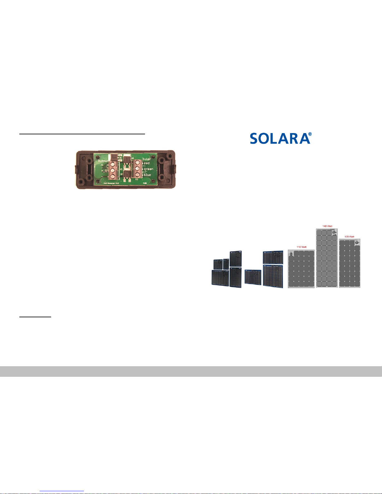
where the Diode Box is to be mounted. (See separate
instructions for wiring the Diode Box.) A Diode Box is included in
the cardboard packing of all panels of 35w and over, and t his
should be located and put to one side when unpacking the panel.
Mount the controller (purchased separately) in the same general location as the
batteries, and r un wires or cable from the Diode Box to the controller that are
appropriately sized to keep volt drop within 3%. (Consult Coastal Climate Control
or NEC or ABYC tables for guidance). If this wiring run is exposed to the elements
it must be made with cable of a suitable composition and construction. Mount the
controller, and then run appropriately sized wire or cable to the battery, battery
switch, bus bar, or whatever connection points are being used to connect to the
vessel’s battery system. The wiring from the controller(s) to the battery must be of
an appropriate size to safely handle the maximum expected current, and must be
protected with a f use rated for 150% of the maximum current expected at the
controller output. NOTE: MPPT controllers are capable of producing 30%+ more
current at their output than is present at the input from the panel.
Example 1 - One Panel 12 volt system
Example 2 - Two Panel 24 volt series system
NOTE: A special boost controller can also be used to connect a single 12v (nom.)
panel to a 24v battery system.
Please consult your marine solar specialist or Coastal Climate Control Inc. for
other possible wiring configurations.